
Related Manuals for Mitsubishi Electric MR-J4-10B(-RJ)


Summary of Contents for Mitsubishi Electric MR-J4-10B(-RJ)
- Page 1 General-Purpose AC Servo SSCNET /H Interface MODEL MR-J4-_B_(-RJ) SERVO AMPLIFIER INSTRUCTION MANUAL...
- Page 2 Safety Instructions Please read the instructions carefully before using the equipment. To use the equipment correctly, do not attempt to install, operate, maintain, or inspect the equipment until you have read through this Instruction Manual, Installation guide, and appended documents carefully. Do not use the equipment until you have a full knowledge of the equipment, safety information and instructions.
- Page 3 1. To prevent electric shock, note the following WARNING Before wiring and inspections, turn off the power and wait for 15 minutes or more until the charge lamp turns off. Then, confirm that the voltage between P+ and N- is safe with a voltage tester and others. Otherwise, an electric shock may occur.
- Page 4 3. To prevent injury, note the following CAUTION Only the power/signal specified in the Instruction Manual should be applied to each terminal. Otherwise, it may cause an electric shock, fire, injury, etc. Connect cables to the correct terminals. Otherwise, a burst, damage, etc., may occur. Ensure that polarity (+/-) is correct.
- Page 5 CAUTION When fumigants that contain halogen materials, such as fluorine, chlorine, bromine, and iodine, are used for disinfecting and protecting wooden packaging from insects, they cause a malfunction when entering our products. Please take necessary precautions to ensure that remaining materials from fumigant do not enter our products, or treat packaging with methods other than fumigation, such as heat treatment.
- Page 6 (3) Test run and adjustment CAUTION When executing a test run, follow the notice and procedures in this instruction manual. Otherwise, it may cause a malfunction, damage to the machine, or injury. Before operation, check and adjust the parameter settings. Improper settings may cause some machines to operate unexpectedly.
- Page 7 (5) Corrective actions CAUTION Ensure safety by confirming the power off, etc. before performing corrective actions. Otherwise, it may cause an accident. If it is assumed that a power failure, machine stoppage, or product malfunction may result in a hazardous situation, use a servo motor with an electromagnetic brake or provide an external brake system for holding purpose to prevent such hazard.
- Page 8 DISPOSAL OF WASTE Please dispose a servo amplifier, battery (primary battery) and other options according to your local laws and regulations. EEP-ROM life The number of write times to the EEP-ROM, which stores parameter settings, etc., is limited to 100,000. If the total number of the following operations exceeds 100,000, the servo amplifier may malfunction when the EEP-ROM reaches the end of its useful life.
- Page 9 «Wiring» Wires mentioned in this Instruction Manual are selected based on the ambient temperature of 40 °C. «U.S. customary units» U.S. customary units are not shown in this manual. Convert the values if necessary according to the following table. Quantity SI (metric) unit U.S.
-
Page 10: Table Of Contents
CONTENTS 1. FUNCTIONS AND CONFIGURATION 1- 1 to 1-52 1.1 Summary ............................1- 1 1.2 Function block diagram ........................1- 3 1.3 Servo amplifier standard specifications ................... 1-13 1.4 Combinations of servo amplifiers and servo motors ............... 1-19 1.5 Function list ............................1-21 1.6 Model designation .......................... - Page 11 3.7.1 When you use the forced stop deceleration function ..............3-33 3.7.2 When you do not use the forced stop deceleration function ............. 3-34 3.8 Interfaces ............................3-35 3.8.1 Internal connection diagram ...................... 3-35 3.8.2 Detailed explanation of interfaces ..................... 3-36 3.8.3 Source I/O interfaces ........................
- Page 12 6.1.2 Adjustment using MR Configurator2 ..................6- 2 6.2 One-touch tuning ..........................6- 3 6.2.1 One-touch tuning flowchart ......................6- 5 6.2.2 Display transition and operation procedure of one-touch tuning ..........6- 7 6.2.3 Caution for one-touch tuning ..................... 6-17 6.3 Auto tuning ............................
- Page 13 10.3 Dynamic brake characteristics ...................... 10- 8 10.3.1 Dynamic brake operation ....................... 10- 9 10.3.2 Permissible load to motor inertia when the dynamic brake is used ........10-12 10.4 Cable bending life ........................10-13 10.5 Inrush currents at power-on of main circuit and control circuit ............ 10-14 11.
- Page 14 12. ABSOLUTE POSITION DETECTION SYSTEM 12- 1 to 12- 6 12.1 Summary ............................12- 1 12.1.1 Features ..........................12- 1 12.1.2 Structure ..........................12- 2 12.1.3 Parameter setting ........................12- 2 12.1.4 Confirmation of absolute position detection data ..............12- 2 12.2 Battery ............................
- Page 15 14.4.3 Dynamic brake characteristics ....................14-32 14.4.4 Permissible load to motor mass ratio when the dynamic brake is used ....... 14-33 15. USING A DIRECT DRIVE MOTOR 15- 1 to 15-22 15.1 Functions and configuration ......................15- 1 15.1.1 Summary ..........................15- 1 15.1.2 Servo system with auxiliary equipment ..................
- Page 16 App. 7 How to replace servo amplifier without magnetic pole detection ......... App.-42 App. 8 Two-wire type encoder cable for HG-MR/HG-KR ..............App.-43 App. 9 SSCNET III cable (SC-J3BUS_M-C) manufactured by Mitsubishi Electric System & Service ..........................App.-45 App. 10 Analog monitor ........................App.-45 App.
- Page 17 MEMO...
-
Page 18: Functions And Configuration
1. FUNCTIONS AND CONFIGURATION 1.1 Summary The Mitsubishi Electric MELSERVO-J4 series general-purpose AC servo has further higher performance and higher functions compared to the previous MELSERVO-J3 series. MR-J4-_B_ servo amplifier is connected to controllers, including a servo system controller, on the high- speed synchronous network SSCNET III/H. - Page 19 1. FUNCTIONS AND CONFIGURATION Table 1.1 Connectors to connect external encoders External encoder Connector Operation communication mode MR-J4-_B_ MR-J4-_B_-RJ method Two-wire type CN2 (Note 1) CN2 (Note 1) Four-wire type Linear servo A/B/Z-phase motor system differential output CN2L (Note 6) method Two-wire type (Note 2, 3, 4)
-
Page 20: Function Block Diagram
1. FUNCTIONS AND CONFIGURATION 1.2 Function block diagram The function block diagram of this servo is shown below. POINT The diagram shows for MR-J4-_B_-RJ as an example. MR-J4-_B_ servo amplifier does not have CN2L connector. (1) 200 V class (a) MR-J4-500B(-RJ) or less (Note 6) Power factor improving Regenerative... - Page 21 1. FUNCTIONS AND CONFIGURATION Note 1. The built-in regenerative resistor is not provided for MR-J4-10B(-RJ). 2. For 1-phase 200 V AC to 240 V AC, connect the power supply to L1 and L3. Leave L2 open. Refer to section 1.3 for the power supply specifications. 3.
- Page 22 1. FUNCTIONS AND CONFIGURATION (b) MR-J4-700B(-RJ) (Note 4) Power factor improving Regenerative DC reactor option Servo amplifier (Note 2) Servo motor Dynamic Diode brake stack Relay circuit MCCB (Note 1) Current Regene- Power encoder rative supply CHARGE lamp Cooling fan Control Electromagnetic circuit...
- Page 23 1. FUNCTIONS AND CONFIGURATION (c) MR-J4-11KB(-RJ)/MR-J4-15KB(-RJ)/MR-J4-22KB(-RJ) (Note 5) External regenerative (Note 4, 6) Power factor improving resistor or DC reactor regenerative option External dynamic brake (optional) Servo amplifier Servo motor P4 (Note 2) Diode stack Thyristor MCCB (Note 1) Current Regene- Power encoder...
- Page 24 1. FUNCTIONS AND CONFIGURATION Note 1. Refer to section 1.3 for the power supply specifications. 2. MR-J4 servo amplifier has P3 and P4 in the upstream of the inrush current suppression circuit. They are different from P1 and P2 of MR-J3 servo amplifiers. 3.
- Page 25 1. FUNCTIONS AND CONFIGURATION (2) 400 V class (a) MR-J4-350B4(-RJ) or less (Note 5) Power factor Regenerative improving option DC reactor Servo amplifier Servo motor P4 (Note 3) Dynamic Diode brake stack Relay circuit MCCB (Note 1) Current Power Regene- detector supply rative...
- Page 26 1. FUNCTIONS AND CONFIGURATION (b) MR-J4-500B4(-RJ)/MR-J4-700B4(-RJ) (Note 4) Power factor Regenerative improving option DC reactor Servo amplifier Servo motor P4 (Note 2) Dynamic Diode brake stack Relay circuit MCCB (Note 1) Current Power Regene- detector supply rative Charge lamp Cooling fan Control Electromagnetic circuit...
- Page 27 1. FUNCTIONS AND CONFIGURATION (c) MR-J4-11KB4(-RJ)/MR-J4-15KB4(-RJ)/MR-J4-22KB4(-RJ) (Note 5) External Power factor regenerative resistor (Note 4, 6) improving DC reactor regenerative option External dynamic brake (optional) Servo amplifier Servo motor P4 (Note 2) Diode Thyristor stack MCCB (Note 1) Current Power Regene- detector supply...
- Page 28 1. FUNCTIONS AND CONFIGURATION Note 1. Refer to section 1.3 for the power supply specification. 2. MR-J4 servo amplifier has P3 and P4 in the upstream of the inrush current suppression circuit. They are different from P1 and P2 of MR-J3 servo amplifiers. 3.
- Page 29 1. FUNCTIONS AND CONFIGURATION (3) 100 V class Regenerative option Servo amplifier Servo motor (Note 1) Dynamic brake circuit MCCB Charge (Note 2) Current lamp Power Regene- encoder supply Relay rative TR Diode stack Control Electromagnetic circuit 24 V DC brake power supply...
-
Page 30: Servo Amplifier Standard Specifications
Fully closed loop control Compatible (Note 7) Scale measurement function Compatible (Note 10) Load-side encoder interface (Note 5) Mitsubishi Electric high-speed serial communication Communication function USB: connection to a personal computer or others (MR Configurator2-compatible) Encoder output pulses Compatible (A/B/Z-phase pulse) - Page 31 1. FUNCTIONS AND CONFIGURATION Model: MR-J4-_(-RJ) 100B 200B 350B 500B 700B 11KB 15KB 22KB Standards certified by CB EN ISO 13849-1 Category 3 PL e, IEC 61508 SIL 3, EN 62061 SIL CL3, EN 61800-5-2 (Note 14) Response performance 8 ms or less (STO input off → energy shut off) Test pulse interval: 1 Hz to 25 Hz Test pulse input (STO) (Note 3)
- Page 32 Fully closed loop control Compatible Scale measurement function Compatible (Note 7) Load-side encoder interface (Note 4) Mitsubishi Electric high-speed serial communication Communication function USB: connection to a personal computer or others (MR Configurator2-compatible) Encoder output pulses Compatible (A/B/Z-phase pulse) Analog monitor...
- Page 33 1. FUNCTIONS AND CONFIGURATION Model: MR-J4-_(-RJ) 60B4 100B4 200B4 350B4 500B4 700B4 11KB4 15KB4 22KB4 Operation 0 ˚C to 55 ˚C (non-freezing) Ambient temperature Storage -20 ˚C to 65 ˚C (non-freezing) Operation Ambient 5 %RH to 90 %RH (non-condensing) humidity Storage Environment Indoors (no direct sunlight),...
- Page 34 Fully closed loop control Compatible (Note 5) Scale measurement function Compatible (Note 7) Load-side encoder interface (Note 4) Mitsubishi Electric high-speed serial communication Communication function USB: connection to a personal computer or others (MR Configurator2-compatible) Encoder output pulses Compatible (A/B/Z-phase pulse)
- Page 35 1. FUNCTIONS AND CONFIGURATION Model: MR-J4-_(-RJ) 10B1 20B1 40B1 Operation 0 °C to 55 °C (non-freezing) Ambient temperature Storage -20 °C to 65 °C (non-freezing) Operation Ambient 5 %RH to 90 %RH (non-condensing) humidity Storage Environment Indoors (no direct sunlight), Ambience free from corrosive gas, flammable gas, oil mist, dust, and dirt Altitude...
-
Page 36: Combinations Of Servo Amplifiers And Servo Motors
1. FUNCTIONS AND CONFIGURATION 1.4 Combinations of servo amplifiers and servo motors POINT When a 1-phase 200 V AC input is used, the maximum torque of 400% cannot be achieved with HG-JR series servo motor. When you use the MR-J4-100B(-RJ) or MR-J4-200B(-RJ) with the 1-phase 200 V AC input, contact your local sales office for the torque characteristics of the HG-UR series, HG-RR series, and HG-JR series servo motors. - Page 37 1. FUNCTIONS AND CONFIGURATION (2) 400 V class Rotary servo motor Linear servo motor Servo amplifier (primary side) HG-SR HG-JR MR-J4-60B4(-RJ) MR-J4-100B4(-RJ) 534 (Note) 1024 1034 MR-J4-200B4(-RJ) 734 (Note) 1524 1034 (Note) 2024 1534 2034 MR-J4-350B4(-RJ) 1534 (Note) 3524 2034 (Note) 3534 MR-J4-500B4(-RJ) 3534 (Note)
-
Page 38: Function List
1. FUNCTIONS AND CONFIGURATION 1.5 Function list The following table lists the functions of this servo. For details of the functions, refer to each section of the detailed description field. Detailed Function Description explanation This realizes a high response and stable control following the ideal model. The two- degrees-of-freedom-model model adaptive control enables you to set a response to the command and response to the disturbance separately. - Page 39 1. FUNCTIONS AND CONFIGURATION Detailed Function Description explanation Fully closed loop system can be configured using the load-side encoder. Fully closed loop system Chapter 16 This is used with servo amplifiers with software version A3 or later. Check the software version of the servo amplifier with MR Configurator2. Gain adjustment is performed just by one click on a certain button on MR Configurator2.
-
Page 40: Model Designation
1. FUNCTIONS AND CONFIGURATION 1.6 Model designation (1) Rating plate The following shows an example of rating plate for explanation of each item. AC SERVO Serial number SER.A45001001 MR-J4-10B MODEL Model Capacity POWER :100W Applicable power supply INPUT : 3AC/AC200-240V 0.9A/1.5A 50/60Hz Rated output current OUTPUT: 3PH170V 0-360Hz 1.1A Standard, Manual number... -
Page 41: Structure
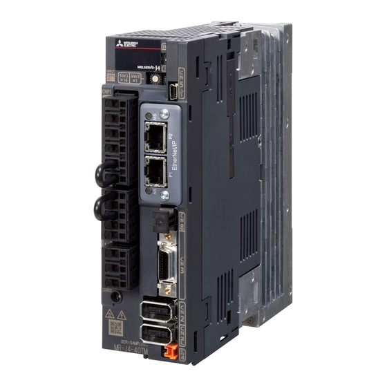
1. FUNCTIONS AND CONFIGURATION 1.7 Structure 1.7.1 Parts identification (1) 200 V class (a) MR-J4-200B(-RJ) or less The diagram is for MR-J4-10B-RJ. Detailed Name/Application explanation Display The 3-digit, 7-segment LED shows the servo status and the alarm number. Axis selection rotary switch (SW1) Section 4.3 Used to set the axis No. - Page 42 1. FUNCTIONS AND CONFIGURATION (b) MR-J4-350B(-RJ) Detailed Name/Application The broken line area is the same as explanation MR-J4-200B(-RJ) or less. Main circuit power connector (CNP1) Section 3.1 Connect the input power supply. Section 3.3 Rating plate Section 1.6 Servo motor power connector (CNP3) Connect the servo motor.
- Page 43 1. FUNCTIONS AND CONFIGURATION (c) MR-J4-500B(-RJ) POINT The servo amplifier is shown with the front cover open. The front cover cannot be removed. Detailed Name/Application The broken line area is the same as explanation MR-J4-200B(-RJ) or less. Control circuit terminal block (TE2) Used to connect the control circuit power supply.
- Page 44 1. FUNCTIONS AND CONFIGURATION (d) MR-J4-700B(-RJ) POINT The servo amplifier is shown without the front cover. For removal of the front cover, refer to section 1.7.2. Detailed Name/Application The broken line area is the same as explanation MR-J4-200B4(-RJ) or less. Power factor improving reactor terminal block (TE3) Used to connect the DC reactor.
- Page 45 1. FUNCTIONS AND CONFIGURATION (e) MR-J4-11KB(-RJ)/MR-J4-15KB(-RJ) POINT The servo amplifier is shown without the front cover. For removal of the front cover, refer to section 1.7.2. Detailed Name/Application The broken line area is the same as explanation MR-J4-200B(-RJ) or less. Power factor improving reactor terminal block (TE1- Used to connect a power factor improving DC reactor and a regenerative option.
- Page 46 1. FUNCTIONS AND CONFIGURATION (f) MR-J4-22KB(-RJ) POINT The servo amplifier is shown without the front cover. For removal of the front cover, refer to section 1.7.2. Detailed Name/Application The broken line area is the same as explanation MR-J4-200B4(-RJ) or less. Power factor improving reactor terminal block (TE1- Used to connect a power factor improving DC reactor and a regenerative option.
- Page 47 1. FUNCTIONS AND CONFIGURATION (2) 400 V class (a) MR-J4-200B4(-RJ) or less The diagram is for MR-J4-60B4-RJ. Detailed Name/Application explanation Display The 3-digit, 7-segment LED shows the servo status and the alarm number. Axis selection rotary switch (SW1) Section 4.3 Used to set the axis No.
- Page 48 1. FUNCTIONS AND CONFIGURATION (b) MR-J4-350B4(-RJ) Detailed Name/Application The broken line area is the same as explanation MR-J4-200B4(-RJ) or less. Main circuit power connector (CNP1) Section 3.1 Connect the input power supply. Section 3.3 Rating plate Section 1.6 Control circuit power connector (CNP2) Connect the control circuit power supply and Section 3.1 regenerative option.
- Page 49 1. FUNCTIONS AND CONFIGURATION (c) MR-J4-500B4(-RJ) POINT The servo amplifier is shown without the front cover. For removal of the front cover, refer to section 1.7.2. Detailed Name/Application The broken line area is the same as explanation MR-J4-200B4(-RJ) or less. Control circuit terminal block (TE2) Used to connect the control circuit power supply.
- Page 50 1. FUNCTIONS AND CONFIGURATION (d) MR-J4-700B4(-RJ) POINT The servo amplifier is shown without the front cover. For removal of the front cover, refer to section 1.7.2. Detailed Name/Application The broken line area is the same as explanation MR-J4-200B4(-RJ) or less. Power factor improving reactor terminal block (TE3) Used to connect the DC reactor.
- Page 51 1. FUNCTIONS AND CONFIGURATION (e) MR-J4-11KB4(-RJ)/MR-J4-15KB4(-RJ) POINT The servo amplifier is shown without the front cover. For removal of the front cover, refer to section 1.7.2. Detailed Name/Application The broken line area is the same as explanation MR-J4-200B4(-RJ) or less. Power factor improving reactor terminal block (TE1-2) Used to connect a power factor improving DC...
- Page 52 1. FUNCTIONS AND CONFIGURATION (f) MR-J4-22KB4(-RJ) POINT The servo amplifier is shown without the front cover. For removal of the front cover, refer to section 1.7.2. Detailed Name/Application The broken line area is the same as explanation MR-J4-200B4(-RJ) or less. Power factor improving reactor terminal block (TE1-2) Used to connect a power factor improving DC...
- Page 53 1. FUNCTIONS AND CONFIGURATION (3) 100 V class The diagram is for MR-J4-10B1-RJ. Detailed Name/Application explanation Display The 3-digit, 7-segment LED shows the servo status and the alarm number. Axis selection rotary switch (SW1) Section 4.3 Used to set the axis No. of servo amplifier. Control axis setting switch (SW2) The test operation switch, the disabling control axis switch and the auxiliary axis number setting switch...
-
Page 54: Removal And Reinstallation Of The
1. FUNCTIONS AND CONFIGURATION 1.7.2 Removal and reinstallation of the front cover Before removing or installing the front cover, turn off the power and wait for 15 minutes or more until the charge lamp turns off. Then, confirm that the voltage WARNING between P+ and N- is safe with a voltage tester and others. - Page 55 1. FUNCTIONS AND CONFIGURATION (2) Reinstallation of the front cover Front cover setting tab 1) Insert the front cover setting tabs into the sockets of 2) Push down the cover, supporting at point A). servo amplifier (2 places). Setting tab 3) Press the cover against the terminal box until the installing knobs click.
-
Page 56: Configuration Including Peripheral Equipment
1. FUNCTIONS AND CONFIGURATION 1.8 Configuration including peripheral equipment Connecting a servo motor of the wrong axis to U, V, W, or CN2 of the servo CAUTION amplifier may cause a malfunction. POINT Equipment other than the servo amplifier and servo motor are optional or recommended products. - Page 57 1. FUNCTIONS AND CONFIGURATION (1) 200 V class (a) MR-J4-200B(-RJ) or less The diagram is for MR-J4-20B-RJ. R S T (Note 2) Power supply Molded-case Personal circuit breaker computer (MCCB) MR Configurator2 (Note 3) Magnetic contactor (MC) (Note 1) Junction terminal block Line noise To safety relay or MR-J3-D05...
- Page 58 1. FUNCTIONS AND CONFIGURATION (b) MR-J4-350B(-RJ) R S T (Note 2) Power supply Molded-case circuit breaker Personal (MCCB) computer MR Configurator2 (Note 3) Magnetic contactor (MC) (Note 1) Junction terminal block Line noise filter To safety relay or MR-J3-D05 (FR-BSF01) safety logic unit Servo system controller or CN1A...
- Page 59 1. FUNCTIONS AND CONFIGURATION (c) MR-J4-500B(-RJ) R S T (Note 2) Power supply Molded-case Personal circuit breaker computer (MCCB) MR Configurator2 (Note 3) Magnetic contactor (MC) (Note 1) Junction terminal block Line noise filter To safety relay or MR-J3-D05 (FR-BLF) safety logic unit Servo system controller or CN1A...
- Page 60 1. FUNCTIONS AND CONFIGURATION (d) MR-J4-700B(-RJ) R S T (Note 2) Power supply Personal computer Molded-case MR Configurator2 circuit breaker (MCCB) (Note 3) Magnetic contactor Junction terminal (MC) block (Note 1) To safety relay or MR-J3-D05 safety logic unit Line noise Servo system controller or filter CN1A...
- Page 61 1. FUNCTIONS AND CONFIGURATION (e) MR-J4-11KB(-RJ)/MR-J4-15KB(-RJ) Personal computer MR Configurator2 R S T (Note 2) Power supply Molded-case circuit breaker (MCCB) Junction terminal block (Note 3) Magnetic To safety relay or MR-J3-D05 contactor safety logic unit (MC) Servo system controller or CN1A (Note 1) previous servo amplifier...
- Page 62 1. FUNCTIONS AND CONFIGURATION (f) MR-J4-22KB(-RJ) R S T (Note 2) Power supply Personal computer Molded-case MR Configurator2 circuit breaker (MCCB) (Note 3) Magnetic contactor Junction terminal (MC) block (Note 1) To safety relay or MR-J3-D05 safety logic unit Line noise Servo system controller or filter CN1A...
- Page 63 1. FUNCTIONS AND CONFIGURATION (2) 400 V class (a) MR-J4-200B4(-RJ) or less The diagram is for MR-J4-60B4-RJ and MR-J4-100B4-RJ. R S T (Note 2) Power supply Molded-case Personal circuit breaker computer (MCCB) MR Configurator2 (Note 3) Magnetic contactor (MC) (Note 1) Junction terminal block To safety relay or...
- Page 64 1. FUNCTIONS AND CONFIGURATION (b) MR-J4-350B4(-RJ) R S T (Note 2) Power supply Molded-case Personal circuit breaker computer (MCCB) MR Configurator2 (Note 3) Magnetic contactor (MC) (Note 1) Junction terminal block To safety relay or MR-J3-D05 safety Line noise filter logic unit (FR-BSF01) Servo system controller...
- Page 65 1. FUNCTIONS AND CONFIGURATION (c) MR-J4-500B4(-RJ) R S T (Note 2) Power supply Personal computer Molded-case MR Configurator2 circuit breaker (MCCB) (Note 3) Magnetic contactor Junction terminal (MC) block (Note 1) Power factor improving DC To safety relay or reactor MR-J3-D05 safety (FR-HEL-H) logic unit...
- Page 66 1. FUNCTIONS AND CONFIGURATION (d) MR-J4-700B4(-RJ) Personal computer MR Configurator2 R S T (Note 2) Power supply Molded-case circuit breaker (MCCB) Junction terminal block (Note 3) Magnetic To safety relay or MR-J3-D05 safety contactor (MC) logic unit Servo system controller (Note 1) CN1A or previous servo...
- Page 67 1. FUNCTIONS AND CONFIGURATION (e) MR-J4-11K4B(-RJ)/MR-J4-15K4B(-RJ) Personal computer MR Configurator2 R S T (Note 2) Power supply Molded-case circuit breaker (MCCB) Junction terminal block (Note 3) To safety relay or Magnetic MR-J3-D05 safety contactor logic unit (MC) Servo system controller CN1A (Note 1) or previous servo...
- Page 68 1. FUNCTIONS AND CONFIGURATION (f) MR-J4-22K4B(-RJ) Personal computer MR Configurator2 R S T (Note 2) Power supply Molded-case circuit breaker Junction terminal (MCCB) block To safety relay or MR-J3-D05 safety logic unit Servo system controller (Note 3) CN1A or previous servo Magnetic amplifier CN1B contactor...
- Page 69 1. FUNCTIONS AND CONFIGURATION (3) 100 V class The diagram is for MR-J4-20B1-RJ. (Note 2) Power supply Molded-case Personal circuit breaker computer (MCCB) MR Configurator2 (Note 3) Magnetic contactor (MC) Power factor (Note 1) (Note 1) Junction terminal improving AC block reactor (FR-HAL)
-
Page 70: Installation
2. INSTALLATION 2. INSTALLATION WARNING To prevent electric shock, ground each equipment securely. Stacking in excess of the specified number of product packages is not allowed. Do not hold the front cover, cables, or connectors when carrying the servo amplifier. Otherwise, it may drop. Install the equipment on incombustible material. -
Page 71: Installation Direction And Clearances
2. INSTALLATION 2.1 Installation direction and clearances The equipment must be installed in the specified direction. Otherwise, it may cause a malfunction. CAUTION Leave specified clearances between the servo amplifier and the cabinet walls or other equipment. Otherwise, it may cause a malfunction. (1) Installation clearances of the servo amplifier (a) Installation of one servo amplifier Cabinet... - Page 72 2. INSTALLATION (b) Installation of two or more servo amplifiers POINT Close mounting is possible depending on the capacity of the servo amplifier. Refer to section 1.3 for availability of close mounting. When closely mounting multiple servo amplifiers, the servo amplifier on the right must have a larger depth than that on the left.
-
Page 73: Keeping Out Of Foreign Materials
2. INSTALLATION 2.2 Keeping out of foreign materials (1) When drilling in the cabinet, prevent drill chips and wire fragments from entering the servo amplifier. (2) Prevent oil, water, metallic dust, etc. from entering the servo amplifier through openings in the cabinet or a cooling fan installed on the ceiling. - Page 74 2. INSTALLATION (2) Prohibition of vinyl tape use Migrating plasticizer is used for vinyl tape. Keep the MR-J3BUS_M, and MR-J3BUS_M-A cables away from vinyl tape because the optical characteristic may be affected. SSCNET III cable Cord Cable MR-J3BUS_M MR-J3BUS_M-A MR-J3BUS_M-B : Phthalate ester plasticizer such as DBP and DOP Optical cord Cable...
-
Page 75: Inspection Items
2. INSTALLATION (5) Tension If tension is added on optical cable, the increase of transmission loss occurs because of external force which concentrates on the fixing part of optical fiber or the connecting part of optical connector. Doing so may cause the breakage of the optical fiber or damage of the optical connector. For cable laying, handle without putting forced tension. -
Page 76: Parts Having Service Life
2. INSTALLATION (5) Check for dust accumulation on the servo amplifier. (6) Check for unusual noise generated from the servo amplifier. (7) Make sure that the emergency stop circuit operates properly such that an operation can be stopped immediately and a power is shut off by the emergency stop switch. 2.6 Parts having service life Service life of the following parts is listed below. -
Page 77: Restrictions When Using This Product At Altitude Exceeding 1000 M And Up To 2000 M Above Sea Level
2. INSTALLATION 2.7 Restrictions when using this product at altitude exceeding 1000 m and up to 2000 m above sea level (1) Effective load ratio and regenerative load ratio As heat dissipation effects decrease in proportion to the decrease in air density, use the product within the effective load ratio and regenerative load ratio shown in the following figure. -
Page 78: Signals And Wiring
3. SIGNALS AND WIRING 3. SIGNALS AND WIRING Any person who is involved in wiring should be fully competent to do the work. Before wiring, turn off the power and wait for 15 minutes or more until the charge lamp turns off. Then, confirm that the voltage between P+ and N- is safe with a voltage tester and others. - Page 79 3. SIGNALS AND WIRING Connect the servo amplifier power output (U/V/W) to the servo motor power input (U/V/W) directly. Do not let a magnetic contactor, etc. intervene. Otherwise, it may cause a malfunction. Servo amplifier Servo motor Servo amplifier Servo motor CAUTION Connecting a servo motor of the wrong axis to U, V, W, or CN2 of the servo amplifier may cause a malfunction.
-
Page 80: Input Power Supply Circuit
3. SIGNALS AND WIRING 3.1 Input power supply circuit Always connect a magnetic contactor between the power supply and the main circuit power supply (L1/L2/L3) of the servo amplifier, in order to configure a circuit that shuts down the power supply on the side of the servo amplifier’s power supply. -
Page 81: Class
3. SIGNALS AND WIRING 3.1.1 200 V class (1) Using 3-phase 200 V AC to 240 V AC power supply for MR-J4-10B(-RJ) to MR-J4-350B(-RJ) (Note 4) Malfunction Emergency stop switch Servo amplifier Servo motor MCCB CNP1 (Note 7) (Note 11) CNP3 3-phase (Note 6) - Page 82 3. SIGNALS AND WIRING (2) Using 1-phase 200 V AC to 240 V AC power supply for MR-J4-10B(-RJ) to MR-J4-200B(-RJ) POINT Connect the 1-phase 200 V AC to 240 V AC power supply to L1 and L3. One of the connecting destinations is different from MR-J3 Series Servo Amplifier's. When using MR-J4 as a replacement for MR-J3, be careful not to connect the power to L2.
- Page 83 3. SIGNALS AND WIRING (3) MR-J4-500B(-RJ) (Note 4) Malfunction Emergency stop switch Servo amplifier Servo motor MCCB (Note 7) (Note 11) 3-phase (Note 6) 200 V AC to Motor 240 V AC (Note 10) (Note 1) (Note 11) (Note 3) Encoder Encoder cable...
- Page 84 3. SIGNALS AND WIRING (4) MR-J4-700B(-RJ) (Note 4) Malfunction Emergency stop switch Servo amplifier Servo motor MCCB (Note 7) (Note 11) 3-phase (Note 6) Built-in 200 V AC to Motor regenerative 240 V AC resistor (Note 2) (Note 10) (Note 11) (Note 3) Encoder Encoder...
- Page 85 3. SIGNALS AND WIRING (5) MR-J4-11KB(-RJ)/MR-J4-15KB(-RJ)/MR-J4-22KB(-RJ) (Note 4) Malfunction (Note 14) Emergency stop switch Cooling fan power supply (Note 15, 16) Servo amplifier Servo motor External dynamic MCCB (Note 7) brake (optional) (Note 11) 3-phase 200 V AC to Motor 240 V AC MCCB (Note 6)
- Page 86 3. SIGNALS AND WIRING Note 1. Between P3 and P4 is connected by default. When using the power factor improving DC reactor, remove the short bar between P3 and P4. Refer to section 11.11 for details. Additionally, a power factor improving DC reactor and power factor improving AC reactor cannot be used simultaneously.
-
Page 87: Class
3. SIGNALS AND WIRING 3.1.2 400 V class (1) MR-J4-60B4(-RJ) to MR-J4-350B4(-RJ) (Note 4) Malfunction Emergency stop switch (Note 12) Step-down Servo amplifier Servo motor transformer CNP1 (Note 11) (Note 7) MCCB CNP3 (Note 6) Motor 3-phase 380 V AC to 480 V AC (Note 10) (Note 1) - Page 88 3. SIGNALS AND WIRING (2) MR-J4-500B4(-RJ)/MR-J4-700B4(-RJ) (Note 4) Malfunction Emergency stop switch (Note 12) Step-down transformer Servo amplifier Servo motor (Note 7) MCCB (Note 11) 3-phase (Note 6) Built-in 380 V AC to Motor regenerative 480 V AC resistor (Note 2) (Note 10) (Note 11) (Note 3)
- Page 89 3. SIGNALS AND WIRING (3) MR-J4-11KB4(-RJ) to MR-J4-22KB4(-RJ) (Note 4) Malfunction (Note 14) (Note 12) Emergency stop switch Cooling fan Step-down power supply transformer (Note 16, 17) Servo amplifier Servo motor External (Note 7) dynamic brake MCCB (optional) (Note 11) 3-phase 380 V AC to Motor...
- Page 90 3. SIGNALS AND WIRING Note 1. Between P3 and P4 is connected by default. When using the power factor improving DC reactor, remove the short bar between P3 and P4. Refer to section 11.11 for details. Additionally, a power factor improving DC reactor and power factor improving AC reactor cannot be used simultaneously.
-
Page 91: Class
3. SIGNALS AND WIRING 3.1.3 100 V class (Note 4) Malfunction Emergency stop switch Servo amplifier Servo motor MCCB CNP1 (Note 7) 1-phase (Note 11) 100 V AC to CNP3 (Note 6) 120 V AC Unassigned Motor Unassigned (Note 10) (Note 1) Unassigned CNP2... -
Page 92: I/O Signal Connection Example
3. SIGNALS AND WIRING 3.2 I/O signal connection example POINT EM2 has the same function as EM1 in the torque control mode. 3.2.1 For sink I/O interface Servo amplifier (Note 16) Short-circuit connector (Packed with the servo amplifier) (Note 12) 10 m or less 10 m or less 24 V DC (Note 10) - Page 93 3. SIGNALS AND WIRING Note 1. To prevent an electric shock, always connect the protective earth (PE) terminal (marked ) of the servo amplifier to the protective earth (PE) of the cabinet. 2. Connect the diode in the correct direction. If it is connected reversely, the servo amplifier will malfunction and will not output signals, disabling EM2 (Forced stop 2) and other protective circuits.
-
Page 94: For Source I/O Interface
3. SIGNALS AND WIRING 3.2.2 For source I/O interface POINT For notes, refer to section 3.2.1. Servo amplifier (Note 16) Short-circuit connector (Packed with the servo amplifier) 10 m or less (Note 12) 10 m or less 24 V DC (Note 10) DOCOM (Note 15) (Note 12) -
Page 95: Explanation Of Power Supply System
3. SIGNALS AND WIRING 3.3 Explanation of power supply system 3.3.1 Signal explanations POINT For the layout of connector and terminal block, refer to chapter 9 DIMENSIONS. When using the MR-J4-_B-RJ servo amplifier with the DC power supply input, refer to app. 15. Connection target Symbol Description... -
Page 96: Power-On Sequence
3. SIGNALS AND WIRING Connection target Symbol Description (application) Supply the following power to L11 and L21. Servo amplifier MR-J4-60B4(-RJ) to MR-J4-10B1 to MR-J4-10B(-RJ) to MR-J4-22KB4(-RJ) MR-J4-40B1 MR-J4-22KB(-RJ) Power 1-phase 200 V AC to L11/L21 Control circuit power 240 V AC, 50 Hz/60 Hz L11/L21 supply 1-phase 380 V AC to... -
Page 97: Wiring Cnp1, Cnp2, And Cnp3
3. SIGNALS AND WIRING (2) Timing chart Servo-on command accepted (Note 1) (3 s to 4 s) Main circuit power supply Control circuit Base circuit 95 ms (Note 2) 10 ms 95 ms Servo-on command (from controller) Note 1. This range will be "5 s to 6 s" for the linear servo system and fully closed loop system. 2. - Page 98 3. SIGNALS AND WIRING (b) MR-J4-200B(-RJ)/MR-J4-350B(-RJ) MR-J4-200B(-RJ) MR-J4-350B(-RJ) Servo amplifier Servo amplifier CNP1 CNP1 CNP2 CNP3 CNP3 CNP2 Table 3.2 Connector and applicable wire Applicable wire Stripped Connector Receptacle assembly Open tool Manufacturer length [mm] Size Insulator OD CNP1 06JFAT-SAXGFK-XL AWG 16 to 10 4.7 mm or shorter 11.5...
- Page 99 3. SIGNALS AND WIRING (d) MR-J4-10B1(-RJ) to MR-J4-40B1(-RJ) Servo amplifier CNP1 CNP2 CNP3 Table 3.4 Connector and applicable wire Applicable wire Stripped Connector Receptacle assembly Open tool Manufacturer length [mm] Size Insulator OD CNP1 06JFAT-SAXGDK-H7.5 J-FAT-OT (N) CNP2 05JFAT-SAXGDK-H5.0 AWG 18 to 14 3.9 mm or shorter J-FAT-OT CNP3...
- Page 100 3. SIGNALS AND WIRING You can also use a ferrule to connect with the connectors. When using a ferrule, select a ferrule and crimping tool listed in the table below. Ferrule model (Phoenix Contact) Crimping tool Servo amplifier Wire size For one For two (Phoenix Contact)
-
Page 101: Connectors And Pin Assignment
3. SIGNALS AND WIRING 3.4 Connectors and pin assignment POINT The pin assignment of the connectors is as viewed from the cable connector wiring section. For the STO I/O signal connector (CN8), refer to chapter 13. For the CN3 connector, securely connect the external conductor of the shielded cable to the ground plate and fix it to the connector shell. - Page 102 3. SIGNALS AND WIRING The servo amplifier front view shown is that of the MR-J4-20B or less. Refer to chapter 9 DIMENSIONS for the appearances and connector layouts of the other servo amplifiers. The frames of the CN2 and CN3 connectors are connected to the protective earth terminal in the servo amplifier.
-
Page 103: Signal (Device) Explanations
3. SIGNALS AND WIRING 3.5 Signal (device) explanations For the I/O interfaces (symbols in I/O division column in the table), refer to section 3.8.2. The pin numbers in the connector pin No. column are those in the initial status. 3.5.1 Input device Connector Device Symbol... -
Page 104: Output Device
3. SIGNALS AND WIRING 3.5.2 Output device (1) Output device pin The following shows the output device pins and parameters for assigning devices. Connector pin No. Parameter Initial device I/O division CN3-13 [Pr. PD07] CN3-9 [Pr. PD08] DO-1 CN3-15 [Pr. PD09] (2) Output device explanations Device Symbol... -
Page 105: Output Signal
3. SIGNALS AND WIRING Device Symbol Function and application Limiting torque When the torque reaches the torque limit value during torque generation, TLC will turn on. When the servo is off, TLC will be turned off. This device cannot be used in the torque control mode. Warning When warning has occurred, WNG turns on. -
Page 106: Forced Stop Deceleration Function
3. SIGNALS AND WIRING 3.6 Forced stop deceleration function POINT When alarms not related to the forced stop function occur, control of motor deceleration cannot be guaranteed. (Refer to chapter 8.) When SSCNET III/H communication shut-off occurs, forced stop deceleration will operate. - Page 107 3. SIGNALS AND WIRING 3.6.1 Forced stop deceleration function When EM2 is turned off, dynamic brake will start to stop the servo motor after forced stop deceleration. During this sequence, the display shows [AL. E6 Servo forced stop warning]. During normal operation, do not use EM2 (Forced stop 2) to alternate stop and drive. The servo amplifier life may be shortened.
-
Page 108: Base Circuit Shut-Off Delay Time Function
3. SIGNALS AND WIRING 3.6.2 Base circuit shut-off delay time function The base circuit shut-off delay time function is used to prevent vertical axis from dropping at a forced stop (EM2 goes off), alarm occurrence, or SSCNET III/H communication shut-off due to delay time of the electromagnetic brake. -
Page 109: Vertical Axis Freefall Prevention Function
3. SIGNALS AND WIRING 3.6.3 Vertical axis freefall prevention function The vertical axis freefall prevention function avoids machine damage by pulling up the shaft slightly like the following case. When the servo motor is used for operating vertical axis, the servo motor electromagnetic brake and the base circuit shut-off delay time function avoid dropping axis at forced stop. -
Page 110: Alarm Occurrence Timing Chart
3. SIGNALS AND WIRING 3.7 Alarm occurrence timing chart When an alarm has occurred, remove its cause, make sure that the operation CAUTION signal is not being input, ensure safety, and reset the alarm before restarting operation. POINT In the torque control mode, the forced stop deceleration function is not available. To deactivate the alarm, cycle the control circuit power or give the error reset or CPU reset command from the servo system controller. - Page 111 3. SIGNALS AND WIRING (2) When the forced stop deceleration function is not enabled Alarm occurrence Braking by the dynamic brake Dynamic brake + Braking by the electromagnetic brake Servo motor speed 0 r/min Base circuit (Energy supply to the servo motor) Servo amplifier No alarm Alarm No.
-
Page 112: Interfaces
3. SIGNALS AND WIRING 3.8 Interfaces 3.8.1 Internal connection diagram POINT Refer to section 13.3.1 for the CN8 connector. Servo amplifier (Note 5) Forced stop 2 24 V DC Approximately 6.2 k DOCOM (Note 3) (Note 2) (Note 1) (Note 3) Approximately 6.2 k DICOM... -
Page 113: Detailed Explanation Of Interfaces
3. SIGNALS AND WIRING 3.8.2 Detailed explanation of interfaces This section provides the details of the I/O signal interfaces (refer to the I/O division in the table) given in section 3.5. Refer to this section and make connection with the external device. (1) Digital input interface DI-1 This is an input circuit whose photocoupler cathode side is the input terminal. - Page 114 3. SIGNALS AND WIRING (3) Encoder output pulses DO-2 (differential line driver type) (a) Interface Maximum output current: 35 mA Servo amplifier Servo amplifier 100 Ω Am26LS32 or equivalent (LB, LZ) (LB, LZ) 150 Ω High-speed photocoupler (LBR, LZR) (LBR, LZR) (b) Output pulse Servo motor CCW rotation Time cycle (T) is determined by the settings of...
-
Page 115: Source I/O Interfaces
3. SIGNALS AND WIRING 3.8.3 Source I/O interfaces In this servo amplifier, source type I/O interfaces can be used. (1) Digital input interface DI-1 This is an input circuit whose photocoupler anode side is the input terminal. Transmit signals from source (open-collector) type transistor output, relay switch, etc. -
Page 116: Sscnet Iii Cable Connection
3. SIGNALS AND WIRING 3.9 SSCNET III cable connection POINT Do not look directly at the light generated from CN1A/CN1B connector of the servo amplifier or the end of SSCNET III cable. The light can be a discomfort when it enters the eye. (1) SSCNET III cable connection For the CN1A connector, connect the SSCNET III cable connected to a controller in host side or a servo amplifier of the previous axis. - Page 117 3. SIGNALS AND WIRING 3) With holding a tab of SSCNET III cable connector, make sure to insert it into the CN1A and CN1B connector of the servo amplifier until you hear the click. If the end face of optical cord tip is dirty, optical transmission is interrupted and it may cause malfunctions.
-
Page 118: Servo Motor With An Electromagnetic Brake
3. SIGNALS AND WIRING 3.10 Servo motor with an electromagnetic brake 3.10.1 Safety precautions Configure an electromagnetic brake circuit which is interlocked with an external emergency stop switch. Contacts must be opened when ALM (Malfunction) Contacts must be opened with the or MBR (Electromagnetic brake interlock) turns off. -
Page 119: Timing Chart
3. SIGNALS AND WIRING (1) Connection diagram Servo amplifier (Note 2) Servo motor 24 V DC (Malfunction) DOCOM (Note 1) 24 V DC Note 1. Create the circuit in order to shut off by interlocking with the emergency stop switch. 2. - Page 120 3. SIGNALS AND WIRING (b) Off/on of the forced stop command (from controller) or EM2 (Forced stop 2) POINT In the torque control mode, the forced stop deceleration function is not available. (Note 2) Model speed command 0 and equal to or less than zero speed Servo motor speed 0 r/min...
- Page 121 3. SIGNALS AND WIRING (e) Main circuit power supply off during control circuit power supply on POINT In the torque control mode, the forced stop deceleration function is not available. Forced stop deceleration Dynamic brake Dynamic brake The time until a voltage Servo motor speed drop is detected.
- Page 122 3. SIGNALS AND WIRING (2) When you do not use the forced stop deceleration function POINT To disable the function, set "0 _ _ _" in [Pr. PA04]. (a) Servo-on command (from controller) on/off It is the same as (1) (a) in this section. (b) Off/on of the forced stop command (from controller) or EM1 (Forced stop 1) Dynamic brake Dynamic brake...
-
Page 123: Grounding
3. SIGNALS AND WIRING (f) Ready-off command from controller It is the same as (1) (f) in this section. 3.11 Grounding Ground the servo amplifier and servo motor securely. WARNING To prevent an electric shock, always connect the protective earth (PE) terminal (marked ) of the servo amplifier to the protective earth (PE) of the cabinet. -
Page 124: Startup
4. STARTUP 4. STARTUP When executing a test run, follow the notice and procedures in this instruction manual. Otherwise, it may cause a malfunction, damage to the machine, or injury. WARNING Do not operate the switches with wet hands. Otherwise, it may cause an electric shock. -
Page 125: Startup Procedure
4. STARTUP 4.1 Switching power on for the first time When switching power on for the first time, follow this section to make a startup. 4.1.1 Startup procedure Check whether the servo amplifier and servo motor are wired correctly using Wiring check visual inspection, DO forced output function (section 4.5.1), etc. - Page 126 4. STARTUP 4.1.2 Wiring check (1) Power supply system wiring Before switching on the main circuit and control circuit power supplies, check the following items. (a) Power supply system wiring 1) The power supplied to the power input terminals (L1/L2/L3/L11/L21) of the servo amplifier should satisfy the defined specifications.
- Page 127 4. STARTUP (c) When you use an option and auxiliary equipment 1) 200 V class a) When you use a regenerative option for 5 kW or less servo amplifiers The lead wire between P+ terminal and D terminal should not be connected. The regenerative option wire should be connected between P+ and C terminal.
- Page 128 4. STARTUP b) When you use a regenerative option for 5 kW or more servo amplifiers For 5 kW or 7 kW servo amplifiers, the lead wire of the built-in regenerative resistor connected to P+ terminal and C terminal should not be connected. The regenerative option should be connected to P+ terminal and C terminal.
-
Page 129: Surrounding Environment
4. STARTUP 4.1.3 Surrounding environment (1) Cable routing (a) The wiring cables should not be stressed. (b) The encoder cable should not be used in excess of its bending life. (Refer to section 10.4.) (c) The connector of the servo motor should not be stressed. (2) Environment Signal cables and power cables are not shorted by wire offcuts, metallic dust or the like. - Page 130 4. STARTUP (4) Home position return Always perform home position return before starting positioning operation. (5) Stop Turn off the servo-on command after the servo motor has stopped, and then switch the power off. If any of the following situations occurs, the servo amplifier suspends the running of the servo motor and brings it to a stop.
-
Page 131: Switch Setting And Display Of The Servo Amplifier
4. STARTUP 4.3 Switch setting and display of the servo amplifier Switching to the test operation mode, deactivating control axes, and setting control axis No. are enabled with switches on the servo amplifier. On the servo amplifier display (three-digit, seven-segment LED), check the status of communication with the servo system controller at power-on, and the axis number, and diagnose a malfunction at occurrence of an alarm. - Page 132 4. STARTUP (2) Disabling control axis switch (SW2-2) Turning "ON (up)" the disabling control axis switch disables the corresponding servo motor. The servo motor will be disabled-axis status and will not be recognized by the controller. 2 3 4 Disabling control axis switch (3) Switches for setting control axis No.
- Page 133 4. STARTUP (c) Switch combination list for the control axis No. setting POINT Set control axis Nos. for one system. For details of the control axis No., refer to the servo system controller user's manual. The following lists show the setting combinations of the auxiliary axis number setting switches and the axis selection rotary switch.
-
Page 134: Scrolling Display
4. STARTUP 4.3.2 Scrolling display (1) Normal display When there is no alarm, the axis No. and blank are displayed in rotation. After 1.6 s Status Blank After 0.2 s Status Axis No. (1 digit) (2 digits) "b" : Indicates ready-off and servo-off status. "C"... - Page 135 4. STARTUP 4.3.3 Status display of an axis (1) Display sequence Servo amplifier power on System check in progress Waiting for servo system controller power to switch on (SSCNET III/H communication) Servo system controller power on (SSCNET III/H communication begins) Initial data communication with the servo system controller (initialization communication)
-
Page 136: Test Operation Mode
4. STARTUP (2) Indication list Indication Status Description Initializing System check in progress Power of the servo amplifier was switched on at the condition that the power of the servo system controller is off. The control axis No. set to the auxiliary axis number setting switches (SW2-3 and SW2-4) and the axis selection rotary switch (SW1) do not match the one set to the servo system controller. -
Page 137: Test Operation
4. STARTUP 4.4 Test operation Before starting actual operation, perform test operation to make sure that the machine operates normally. Refer to section 4.2 for the power on and off methods of the servo amplifier. POINT If necessary, verify controller program by using motor-less operation. Refer to section 4.5.2 for the motor-less operation. -
Page 138: Test Operation Mode In Mr Configurator2
4. STARTUP 4.5.1 Test operation mode in MR Configurator2 POINT When the test operation mode is selected with the test operation select switch (SW2-1), the SSCNET III/H communication for the servo amplifier in the test operation mode and the following servo amplifiers is blocked. (1) Test operation mode (a) Jog operation Jog operation can be performed without using the servo system controller. - Page 139 4. STARTUP (b) Positioning operation Positioning operation can be performed without using the servo system controller. Use this operation with the forced stop reset. This operation may be used independently of whether the servo is on or off and whether the servo system controller is connected or not. Exercise control on the positioning operation screen of MR Configurator2.
- Page 140 4. STARTUP (2) Operation procedure 1) Turn off the power. 2) Turn "ON (up)" SW2-1. Set SW2-1 to "ON (up)". 1 2 3 4 2 3 4 Turning "ON (up)" SW2-1 during power-on will not start the test operation mode. 3) Turn on the servo amplifier.
-
Page 141: Motor-Less Operation In Controller
4. STARTUP 4.5.2 Motor-less operation in controller POINT Use motor-less operation which is available by making the servo system controller servo parameter setting. Connect the servo system controller to the servo amplifier before the motor-less operation. The motor-less operation is not used in the fully closed loop control mode, linear servo motor control mode, and DD motor control mode. - Page 142 4. STARTUP (2) Operation procedure 1) Set the servo amplifier to the servo-off status. 2) Set [Pr. PC05] to "_ _ _ 1", turn "OFF (down: normal condition side)" the test operation mode switch (SW2-1), and then turn on the power supply. Set SW2-1 to "OFF (down)".
- Page 143 4. STARTUP MEMO 4 - 20...
-
Page 144: Parameters
5. PARAMETERS 5. PARAMETERS Never make a drastic adjustment or change to the parameter values as doing so will make the operation unstable. Do not change the parameter settings as described below. Doing so may cause an unexpected condition, such as failing to start up the servo amplifier. Changing the values of the parameters for manufacturer setting CAUTION Setting a value out of the range... - Page 145 5. PARAMETERS 5.1.1 Basic setting parameters ([Pr. PA_ _ ]) Operation mode Initial Symbol Name Unit value PA01 **STY Operation mode 1000h PA02 **REG Regenerative option 0000h PA03 *ABS Absolute position detection system 0000h PA04 *AOP1 Function selection A-1 2000h PA05 For manufacturer setting 10000...
- Page 146 5. PARAMETERS 5.1.2 Gain/filter setting parameters ([Pr. PB_ _ ]) Operation mode Initial Symbol Name Unit value PB01 FILT Adaptive tuning mode (adaptive filter II) 0000h PB02 VRFT Vibration suppression control tuning mode (advanced vibration 0000h suppression control II) PB03 TFBGN Torque feedback loop gain 18000...
- Page 147 5. PARAMETERS Operation mode Initial Symbol Name Unit value PB46 Machine resonance suppression filter 3 4500 [Hz] PB47 NHQ3 Notch shape selection 3 0000h PB48 Machine resonance suppression filter 4 4500 [Hz] PB49 NHQ4 Notch shape selection 4 0000h PB50 Machine resonance suppression filter 5 4500 [Hz]...
- Page 148 5. PARAMETERS Operation mode Initial Symbol Name Unit value PC21 *BPS Alarm history clear 0000h PC22 For manufacturer setting PC23 0000h PC24 RSBR Forced stop deceleration time constant [ms] PC25 For manufacturer setting PC26 **COP8 Function selection C-8 0000h (Note) PC27 **COP9 Function selection C-9...
- Page 149 5. PARAMETERS 5.1.4 I/O setting parameters ([Pr. PD_ _ ]) Operation mode Initial Symbol Name Unit value PD01 For manufacturer setting 0000h PD02 *DIA2 Input signal automatic on selection 2 0000h PD03 For manufacturer setting 0020h PD04 0021h PD05 0022h PD06 0000h PD07...
- Page 150 5. PARAMETERS 5.1.5 Extension setting 2 parameters ([Pr. PE_ _ ]) Operation mode Initial Symbol Name Unit value PE01 **FCT1 Fully closed loop function selection 1 0000h PE02 For manufacturer setting 0000h PE03 *FCT2 Fully closed loop function selection 2 0003h PE04 **FBN...
- Page 151 5. PARAMETERS Operation mode Initial Symbol Name Unit value PE51 For manufacturer setting 0000h PE52 0000h PE53 0000h PE54 0000h PE55 0000h PE56 0000h PE57 0000h PE58 0000h PE59 0000h PE60 0000h PE61 0.00 PE62 0.00 PE63 0.00 PE64 0.00 5.1.6 Extension setting 3 parameters ([Pr.
- Page 152 5. PARAMETERS Operation mode Initial Symbol Name Unit value PF29 For manufacturer setting 0000h PF30 PF31 FRIC Machine diagnosis function - Friction judgment speed [r/min]/ [mm/s] PF32 For manufacturer setting PF33 0000h PF34 0000h PF35 0000h PF36 0000h PF37 0000h PF38 0000h PF39...
- Page 153 5. PARAMETERS Operation mode Initial Symbol Name Unit value PL19 For manufacturer setting PL20 PL21 PL22 PL23 0000h PL24 PL25 0000h PL26 0000h PL27 0000h PL28 0000h PL29 0000h PL30 0000h PL31 0000h PL32 0000h PL33 0000h PL34 0000h PL35 0000h PL36 0000h...
-
Page 154: Basic Setting Parameters ([Pr. Pa
5. PARAMETERS 5.2 Detailed list of parameters POINT Set a value to each "x" in the "Setting digit" columns. 5.2.1 Basic setting parameters ([Pr. PA_ _ ]) Initial Setting Symbol Name and function value range [unit] PA01 **STY Operation mode Refer to the "Name and Select a operation mode. - Page 155 5. PARAMETERS Initial Setting Symbol Name and function value range [unit] PA02 **REG Regenerative option Refer to the "Name and Used to select the regenerative option. function" column. Incorrect setting may cause the regenerative option to burn. If a selected regenerative option is not for use with the servo amplifier, [AL. 37 Parameter error] occurs.
- Page 156 5. PARAMETERS Initial Setting Symbol Name and function value range [unit] PA03 *ABS Absolute position detection system Refer to the "Name and Set this parameter when using the absolute position detection system. function" column. Setting Initial Explanation digit value _ _ _ x Absolute position detection system selection 0: Disabled (used in incremental system) 1: Enabled (used in absolute position detection system)
- Page 157 5. PARAMETERS Initial Setting Symbol Name and function value range [unit] PA08 Auto tuning mode Refer to the "Name and Select the gain adjustment mode. function" column. Setting Initial Explanation digit value _ _ _ x Gain adjustment mode selection 0: 2 gain adjustment mode 1 (interpolation mode) 1: Auto tuning mode 1 2: Auto tuning mode 2...
- Page 158 5. PARAMETERS Initial Setting Symbol Name and function value range [unit] PA09 Auto tuning response 1 to 40 Set a response of the auto tuning. Machine characteristic Machine characteristic Guideline for Guideline for Setting Setting machine machine value value Response Response resonance resonance...
- Page 159 5. PARAMETERS Initial Setting Symbol Name and function value range [unit] PA14 *POL Rotation direction selection/travel direction selection 0 to 1 Select the rotation direction or travel direction of command input pulses of the rotary servo motor, linear servo motor and direct drive motor. For the setting for the master-slave operation function, refer to section 17.2.
- Page 160 5. PARAMETERS Initial Setting Symbol Name and function value range [unit] PA17 **MSR Servo motor series setting 0000h Refer to When you use a linear servo motor, select its model from [Pr. PA17] and [Pr. PA18]. Set this "Name and [Pr. PA18] at a time. Refer to the following table for settings.
- Page 161 5. PARAMETERS Initial Setting Symbol Name and function value range [unit] PA17 **MSR 0000h Refer to Linear servo motor Linear servo motor Parameter "Name series (primary side) LM-K2P1A-01M-2SS1 1101h function" LM-K2P1C-03M-2SS1 1301h column. LM-K2P2A-02M-1SS1 2101h LM-K2 LM-K2P2C-07M-1SS1 00B8h 2301h LM-K2P2E-12M-1SS1 2501h LM-K2P3C-14M-1SS1 3301h...
- Page 162 5. PARAMETERS Initial Setting Symbol Name and function value range [unit] PA20 *TDS Tough drive setting Refer to the "Name and Alarms may not be avoided with the tough drive function depending on the situations of the function" column. power supply and load fluctuation. You can assign MTTR (During tough drive) to pins CN3-9, CN3-13 and CN3-15 with [Pr.
- Page 163 5. PARAMETERS Initial Setting Symbol Name and function value range [unit] PA22 **PCS Position control composition selection Refer to the "Name and Setting Initial function" column. Explanation digit value _ _ _ x For manufacturer setting _ _ x _ Super trace control selection 0: Disabled 2: Enabled...
- Page 164 5. PARAMETERS Initial Setting Symbol Name and function value range [unit] PA25 OTHOV One-touch tuning - Overshoot permissible level 0 to 100 This is used to set a permissible value of overshoot amount with a percentage to in-position range. However, setting "0" will be 50%. PA26 *AOP5 Function selection A-5...
-
Page 165: Gain/Filter Setting Parameters ([Pr. Pb
5. PARAMETERS 5.2.2 Gain/filter setting parameters ([Pr. PB_ _ ]) Initial Setting Symbol Name and function value range [unit] PB01 FILT Adaptive tuning mode (adaptive filter II) Refer to the "Name and Set the adaptive tuning. function" column. Setting Initial Explanation digit value... - Page 166 5. PARAMETERS Initial Setting Symbol Name and function value range [unit] PB06 Load to motor inertia ratio/load to motor mass ratio 7.00 0.00 to Multiplier 300.00 This is used to set the load to motor inertia ratio or load to motor mass ratio. Setting a value considerably different from the actual load moment of inertia or load mass may cause an unexpected operation such as an overshoot.
- Page 167 5. PARAMETERS Initial Setting Symbol Name and function value range [unit] PB11 Speed differential compensation 0 to 1000 This is used to set the differential compensation. To enable the parameter, select "Continuous PID control enabled (_ _ 3 _)" of "PI-PID switching control selection"...
- Page 168 5. PARAMETERS Initial Setting Symbol Name and function value range [unit] PB17 Shaft resonance suppression filter Refer to the "Name and This is used for setting the shaft resonance suppression filter. function" column. This is used to suppress a low-frequency machine vibration. When you select "Automatic setting (_ _ _ 0)"...
- Page 169 5. PARAMETERS Initial Setting value Symbol Name and function range [unit] PB19 VRF11 Vibration suppression control 1 - Vibration frequency 100.0 Set the vibration frequency for vibration suppression control 1 to suppress low-frequency [Hz] machine vibration. 300.0 When "Vibration suppression control 1 tuning mode selection" is set to "Automatic setting (_ _ _ 1)"...
- Page 170 5. PARAMETERS Initial Setting value Symbol Name and function range [unit] PB24 *MVS Slight vibration suppression control Refer to the "Name and Select the slight vibration suppression control and PI-PID switching control. function" column. Setting Initial Explanation digit value _ _ _ x Slight vibration suppression control selection 0: Disabled 1: Enabled...
- Page 171 5. PARAMETERS Initial Setting value Symbol Name and function range [unit] PB26 *CDP Gain switching function Refer to the "Name and Select the gain switching condition. function" column. Set conditions to enable the gain switching values set in [Pr. PB29] to [Pr. PB36] and [Pr. PB56] to [Pr.
- Page 172 5. PARAMETERS Initial Setting value Symbol Name and function range [unit] Position loop gain after gain switching 0.0 to PB30 PG2B [rad/s] 2000.0 Set the position loop gain when the gain switching is enabled. When you set a value less than 1.0 rad/s, the value will be the same as [Pr. PB08]. This parameter is enabled only when you select "Manual mode (_ _ _ 3)"...
- Page 173 5. PARAMETERS Initial Setting value Symbol Name and function range [unit] PB45 CNHF Command notch filter Refer to the "Name and Set the command notch filter. function" column. Setting Initial Explanation digit value _ _ x x Command notch filter setting frequency selection Refer to table 5.5 for the relation of setting values to frequency.
- Page 174 5. PARAMETERS Initial Setting Symbol Name and function value range [unit] PB45 CNHF Refer to the Table 5.6 Notch depth selection "Name and Setting Setting function" column. Depth [dB] Depth [dB] value value _ 0 _ _ -40.0 _ 8 _ _ -6.0 _ 1 _ _ -24.1...
- Page 175 5. PARAMETERS Initial Setting Symbol Name and function value range [unit] PB49 NHQ4 Notch shape selection 4 Refer to the "Name and Set the shape of the machine resonance suppression filter 4. function" column. Setting Initial Explanation digit value _ _ _ x Machine resonance suppression filter 4 selection 0: Disabled 1: Enabled...
- Page 176 5. PARAMETERS Initial Setting Symbol Name and function value range [unit] PB53 VRF22 Vibration suppression control 2 - Resonance frequency 100.0 0.1 to [Hz] 300.0 Set the resonance frequency for vibration suppression control 2 to suppress low-frequency machine vibration. To enable the setting value, set "Vibration suppression mode selection" to "3 inertia mode (_ _ _ 1)"...
- Page 177 5. PARAMETERS Initial Setting Symbol Name and function value range [unit] PB58 VRF23B Vibration suppression control 2 - Vibration frequency damping after gain switching 0.00 0.00 to 0.30 Set a damping of the vibration frequency for vibration suppression control 2 when the gain switching is enabled.
-
Page 178: Extension Setting Parameters ([Pr. Pc_ _ ])
5. PARAMETERS 5.2.3 Extension setting parameters ([Pr. PC_ _ ]) Initial Setting Symbol Name and function value range [unit] PC01 Error excessive alarm level 0 to [rev]/ 1000 Set an error excessive alarm level. [mm] Set this per rev. for rotary servo motors and direct drive motors. Setting "0" will be 3 rev. (Note) Setting over 200 rev will be clamped with 200 rev. - Page 179 5. PARAMETERS Initial Setting Symbol Name and function value range [unit] PC04 **COP1 Function selection C-1 Refer to the "Name and Select the encoder cable communication method selection. function" column. Setting Initial Explanation digit value _ _ _ x For manufacturer setting _ _ x _ _ x _ _ x _ _ _...
- Page 180 5. PARAMETERS Initial Setting Symbol Name and function value range [unit] PC09 MOD1 Analog monitor 1 output Refer to the "Name and Select a signal to output to MO1 (Analog monitor 1). Refer to app. 11.3 for detection point of function"...
- Page 181 5. PARAMETERS Initial Setting Symbol Name and function value range [unit] PC10 MOD2 Analog monitor 2 output Refer to the "Name and Select a signal to output to MO2 (Analog monitor 2). Refer to app. 11.3 for detection point of function"...
- Page 182 5. PARAMETERS Initial Setting Symbol Name and function value range [unit] PC20 *COP7 Function selection C-7 Refer to the "Name and This is used to select an undervoltage alarm detection method. function" column. Setting Initial Explanation digit value _ _ _ x [AL.
- Page 183 5. PARAMETERS Initial Setting Symbol Name and function value range [unit] PC24 RSBR Forced stop deceleration time constant 0 to [ms] 20000 This is used to set deceleration time constant when you use the forced stop deceleration function. Set the time per ms from the rated speed to 0 r/min or 0 mm/s. Setting "0" will be 100 ms. Dynamic brake Forced stop deceleration Rated speed...
- Page 184 5. PARAMETERS Initial Setting Symbol Name and function value range [unit] PC27 **COP9 Function selection C-9 Refer to the "Name and This is used to select a polarity of the linear encoder or load-side encoder. function" column. Setting Initial Explanation digit value _ _ _ x...
-
Page 185: I/O Setting Parameters ([Pr. Pd
5. PARAMETERS Initial Setting Symbol Name and function value range [unit] PC38 Error excessive warning level [rev]/ Set an error excessive warning level. [mm] 1000 To enable the parameter, select "Enabled (1 _ _ _)" of "[AL. 9B Error excessive warning] selection"... - Page 186 5. PARAMETERS Initial Setting Symbol Name and function value range [unit] PD07 *DO1 Output device selection 1 Refer to the "Name and You can assign any output device to the CN3-13 pin. MBR (Electromagnetic brake interlock) is function" column. assigned as the initial value. Setting Initial Explanation...
- Page 187 5. PARAMETERS Initial Setting Symbol Name and function value range [unit] PD11 *DIF Input filter setting Refer to the "Name and Select the input filter. function" column. Setting Initial Explanation digit value _ _ _ x Input signal filter selection Refer to the servo system controller instruction manual for the setting.
- Page 188 5. PARAMETERS Initial Setting Symbol Name and function value range [unit] PD14 *DOP3 Function selection D-3 Refer to the "Name and Setting Initial function" column. Explanation digit value _ _ _ x For manufacturer setting _ _ x _ Selection of output device at warning occurrence Select WNG (Warning) and ALM (Malfunction) output status at warning occurrence.
- Page 189 5. PARAMETERS Initial Setting Symbol Name and function value range [unit] PD16 *MD1 Driver communication setting - Master - Transmit data selection 1 Refer to the "Name and This parameter is used to select transmit data from master axis to slave axis. function"...
- Page 190 5. PARAMETERS Initial Setting Symbol Name and function value range [unit] PD31 Master-slave operation - Speed limit coefficient on slave 0 [%] 0 to 500 This parameter is used to set a internal speed limit value coefficient to speed limit command value received from master axis.
-
Page 191: Extension Setting 2 Parameters ([Pr. Pe_ _ ])
5. PARAMETERS 5.2.5 Extension setting 2 parameters ([Pr. PE_ _ ]) Initial Setting Symbol Name and function value range [unit] PE01 **FCT1 Fully closed loop function selection 1 Refer to the "Name and Setting Initial function" column. Explanation digit value _ _ _ x Fully closed loop function selection 0: Always enabled... - Page 192 5. PARAMETERS Initial Setting value Symbol Name and function range [unit] PE08 Fully closed loop dual feedback filter 0 to [rad/s] 4500 This is used to set a dual feedback filter band. Refer to section 16.3.1 (7) for details. PE10 FCT3 Fully closed loop function selection 3 Refer to the...
- Page 193 5. PARAMETERS Initial Setting value Symbol Name and function range [unit] PE46 LMFLT Lost motion filter setting [0.1 ms] Set the time constant of the lost motion compensation filter in increments of 0.1 ms. 30000 If the time constant is "0", the torque is compensated with the value set in [Pr. PE44] and [Pr. PE45].
-
Page 194: Extension Setting 3 Parameters ([Pr. Pf
5. PARAMETERS 5.2.6 Extension setting 3 parameters ([Pr. PF_ _ ]) Initial Setting Symbol Name and function value range [unit] PF06 *FOP5 Function selection F-5 Refer to the "Name and Setting Initial function" column. Explanation digit value _ _ _ x Electronic dynamic brake selection 0: Automatic (enabled only for specified servo motors) 2: Disabled... - Page 195 5. PARAMETERS Initial Setting Symbol Name and function value range [unit] PF23 OSCL1 Vibration tough drive - Oscillation detection level 0 to 100 This is used to set a filter readjustment sensitivity of [Pr. PB13 Machine resonance suppression filter 1] and [Pr. PB15 Machine resonance suppression filter 2] while the vibration tough drive is enabled.
-
Page 196: Linear Servo Motor/Dd Motor Setting Parameters ([Pr. Pl_ _ ])
5. PARAMETERS 5.2.7 Linear servo motor/DD motor setting parameters ([Pr. PL_ _ ]) Initial Setting Symbol Name and function value range [unit] PL01 **LIT1 Linear servo motor/DD motor function selection 1 Refer to the "Name and Select a magnetic pole detection timing of the linear servo motor/DD motor and stop interval of function"... - Page 197 5. PARAMETERS Initial Setting value Symbol Name and function range [unit] Linear servo motor/DD motor function selection 2 Refer to the PL04 *LIT2 "Name and This is used to select a detection function and detection controller reset condition of [AL. 42 function"...
- Page 198 5. PARAMETERS Initial Setting Symbol Name and function value range [unit] PL09 LPWM Magnetic pole detection voltage level 0 to 100 This is used to set a direct current exciting voltage level during the magnetic pole detection. If [AL. 32 Overcurrent], [AL. 50 Overload 1], or [AL. 51 Overload 2] occurs during the magnetic pole detection, decrease the setting value.
- Page 199 5. PARAMETERS MEMO 5 - 56...
-
Page 200: Normal Gain Adjustment
6. NORMAL GAIN ADJUSTMENT 6. NORMAL GAIN ADJUSTMENT POINT In the torque control mode, you do not need to make gain adjustment. Before making gain adjustment, check that your machine is not being operated at maximum torque of the servo motor. If operated over maximum torque, the machine may vibrate and may operate unexpectedly. -
Page 201: Adjustment Using Mr Configurator2
6. NORMAL GAIN ADJUSTMENT (2) Adjustment sequence and mode usage Start Interpolation 2 gain adjustment mode 1 made for 2 or more (interpolation mode) axes? The load fluctuation is large during driving? One-touch tuning Handle the error Error handling Finished normally? Auto tuning mode 1 is possible? Adjustment OK? -
Page 202: One-Touch Tuning
6. NORMAL GAIN ADJUSTMENT 6.2 One-touch tuning POINT After the one-touch tuning is completed, "Gain adjustment mode selection" in [Pr. PA08] will be set to "2 gain adjustment mode 2 (_ _ _ 4)". To estimate [Pr. PB06 Load to motor inertia ratio/load to motor mass ratio] again, set "Gain adjustment mode selection"... - Page 203 6. NORMAL GAIN ADJUSTMENT The following parameters are set automatically with one-touch tuning. Also, "Gain adjustment mode selection" in [Pr. PA08] will be "2 gain adjustment mode 2 (_ _ _ 4)" automatically. Other parameters will be set to an optimum value depending on the setting of [Pr. PA09 Auto tuning response]. Table 6.1 List of parameters automatically set with one-touch tuning Parameter Symbol...
-
Page 204: One-Touch Tuning Flowchart
6. NORMAL GAIN ADJUSTMENT 6.2.1 One-touch tuning flowchart (1) User command method Make one-touch tuning as follows. Start Start a system referring to chapter 4. Startup of the system Rotate the servo motor by a servo system controller. (In the user command method, the one- Operation touch tuning cannot be executed if the servo motor is not operating.) One-touch tuning start,... - Page 205 6. NORMAL GAIN ADJUSTMENT (2) Amplifier command method Make one-touch tuning as follows. Start Start a system referring to chapter 4. Startup of the system Move the moving part to the center of a movable range. Movement to tuning start position Start one-touch tuning of MR Configurator2, and select "Amplifier command method".
-
Page 206: Display Transition And Operation Procedure Of One-Touch Tuning
6. NORMAL GAIN ADJUSTMENT 6.2.2 Display transition and operation procedure of one-touch tuning (1) Command method selection Select a command method from two methods in the one-touch tuning window of MR Configurator2. 6 - 7... - Page 207 6. NORMAL GAIN ADJUSTMENT (a) User command method It is recommended to input commands meeting the following conditions to the servo amplifier. If one- touch tuning is executed while commands which do not meet the conditions are inputted to the servo amplifier, the one-touch tuning error may occur.
- Page 208 6. NORMAL GAIN ADJUSTMENT (b) Amplifier command method Input a permissible travel distance. Input it in the load-side resolution unit for the fully closed loop control mode, and in the servo motor-side resolution unit for other control modes. In the amplifier command method, the servo motor will be operated in a range between "current value ±...
- Page 209 6. NORMAL GAIN ADJUSTMENT (2) Response mode selection Select a response mode from 3 modes in the one-touch tuning window of MR Configurator2. Table 6.2 Response mode explanations Response mode Explanation High mode This mode is for high-rigid system. Basic mode This mode is for standard system.
- Page 210 6. NORMAL GAIN ADJUSTMENT Refer to the following table for selecting a response mode. Table 6.3 Guideline for response mode Response mode Machine characteristic Response Low mode Basic mode High mode Guideline of corresponding machine Low response Arm robot General machine tool conveyor Precision working machine...
- Page 211 6. NORMAL GAIN ADJUSTMENT After one-touch tuning is executed using the amplifier command method, control will not be performed by commands from the controller. To return to the state in which control is performed by commands from the controller, reset the controller or cycle the power. During processing of one-touch tuning, the progress will be displayed as follows.
- Page 212 6. NORMAL GAIN ADJUSTMENT After the one-touch tuning is completed, "0000" will be displayed at status in error code. In addition, settling time and overshoot amount will be displayed in "Adjustment result". (4) Stop of one-touch tuning When "Stop" is clicked during one-touch tuning, the tuning will be stopped. At this time, "C000" will be displayed at status in error code.
- Page 213 6. NORMAL GAIN ADJUSTMENT (5) If an error occurs If a tuning error occurs during tuning, one-touch tuning will be stopped. With that, the following error code will be displayed in status. Check the cause of tuning error. When executing one-touch tuning again, stop the servo motor once.
- Page 214 6. NORMAL GAIN ADJUSTMENT Display Name Error detail Corrective action example C006 Amplifier command start One-touch tuning was attempted to start in Execute the one-touch tuning in the amplifier error the amplifier command method under the command method while the servo motor is following speed condition.
- Page 215 6. NORMAL GAIN ADJUSTMENT (8) Initializing one-touch tuning Clicking "Return to initial value" in the one-touch tuning window of MR Configurator2 enables to return the parameter to the initial value. Refer to table 6.1 for the parameters which you can initialize. Clicking "Return to value before adjustment"...
-
Page 216: Caution For One-Touch Tuning
6. NORMAL GAIN ADJUSTMENT 6.2.3 Caution for one-touch tuning (1) Caution common for user command method and amplifier command method (a) The tuning is not available in the torque control mode. (b) The one-touch tuning cannot be executed while an alarm or warning which does not continue the motor driving is occurring. -
Page 217: Auto Tuning
6. NORMAL GAIN ADJUSTMENT 6.3 Auto tuning 6.3.1 Auto tuning mode The servo amplifier has a real-time auto tuning function which estimates the machine characteristic (load to motor inertia ratio) in real time and automatically sets the optimum gains according to that value. This function permits ease of gain adjustment of the servo amplifier. - Page 218 6. NORMAL GAIN ADJUSTMENT 6.3.2 Auto tuning mode basis The block diagram of real-time auto tuning is shown below. Load moment Automatic setting of inertia Encoder Loop gain Command Current PG1, PG2, control VG2, VIC Servo motor Current feedback Real-time Position/speed Set 0 or 1 to turn on.
-
Page 219: Adjustment Procedure By Auto Tuning
6. NORMAL GAIN ADJUSTMENT 6.3.3 Adjustment procedure by auto tuning Since auto tuning is enabled before shipment from the factory, simply running the servo motor automatically sets the optimum gains that match the machine. Merely changing the response level setting value as required completes the adjustment. -
Page 220: Response Level Setting In Auto Tuning Mode
6. NORMAL GAIN ADJUSTMENT 6.3.4 Response level setting in auto tuning mode Set the response of the whole servo system by [Pr. PA09]. As the response level setting is increased, the trackability to a command improves and settling time decreases, but setting the response level too high will generate vibration. -
Page 221: Manual Mode
6. NORMAL GAIN ADJUSTMENT 6.4 Manual mode If you are not satisfied with the adjustment of auto tuning, you can adjust all gains manually. POINT If machine resonance occurs, filter tuning mode selection in [Pr. PB01] or machine resonance suppression filter in [Pr. PB13] to [Pr. PB16] and [Pr. PB46] to [Pr. - Page 222 6. NORMAL GAIN ADJUSTMENT (c) Parameter adjustment 1) [Pr. PB09 Speed loop gain] This parameter determines the response level of the speed control loop. Increasing this value enhances response but a too high value will make the mechanical system liable to vibrate. The actual response frequency of the speed loop is as indicated in the following expression.
- Page 223 6. NORMAL GAIN ADJUSTMENT (b) Adjustment procedure Step Operation Description Brief-adjust with auto tuning. Refer to section 6.2.3. Change the setting of auto tuning to the manual mode ([Pr. PA08]: _ _ _ 3). Set the estimated value to the load to motor inertia ratio/load to motor mass ratio.
-
Page 224: Gain Adjustment Mode
6. NORMAL GAIN ADJUSTMENT 3) [Pr. PB08 Position loop gain] This parameter determines the response level to a disturbance to the position control loop. Increasing the value increases the response level to the disturbance, but a too high value will increase vibration of the mechanical system. - Page 225 6. NORMAL GAIN ADJUSTMENT (2) 2 gain adjustment mode 2 Use 2 gain adjustment mode 2 when proper gain adjustment cannot be made with 2 gain adjustment mode 1. Since the load to motor inertia ratio is not estimated in this mode, set the value of a proper load to motor inertia ratio in [Pr.
- Page 226 6. NORMAL GAIN ADJUSTMENT (4) Parameter adjustment [Pr. PB07 Model loop gain] This parameter determines the response level of the position control loop. Increasing the value improves trackability to a position command, but a too high value will make overshoot liable to occur at settling. Number of droop pulses is determined by the following expression.
- Page 227 6. NORMAL GAIN ADJUSTMENT MEMO 6 - 28...
-
Page 228: Special Adjustment Functions
7. SPECIAL ADJUSTMENT FUNCTIONS 7. SPECIAL ADJUSTMENT FUNCTIONS POINT The functions given in this chapter need not be used normally. Use them if you are not satisfied with the machine status after making adjustment in the methods in chapter 6. When you use a linear servo motor, replace the following words in the left to the words in the right. -
Page 229: Machine Resonance Suppression Filter
7. SPECIAL ADJUSTMENT FUNCTIONS 7.1.1 Machine resonance suppression filter POINT The machine resonance suppression filter is a delay factor for the servo system. Therefore, vibration may increase if you set an incorrect resonance frequency or set notch characteristics too deep or too wide. If the frequency of machine resonance is unknown, decrease the notch frequency from higher to lower ones in order. - Page 230 7. SPECIAL ADJUSTMENT FUNCTIONS (1) Function The machine resonance suppression filter is a filter function (notch filter) which decreases the gain of the specific frequency to suppress the resonance of the mechanical system. You can set the gain decreasing frequency (notch frequency), gain decreasing depth and width. Machine resonance point Frequency Notch width...
- Page 231 7. SPECIAL ADJUSTMENT FUNCTIONS (2) Parameter (a) Machine resonance suppression filter 1 ([Pr. PB13]/[Pr. PB14]) Set the notch frequency, notch depth and notch width of the machine resonance suppression filter 1 ([Pr. PB13]/[Pr. PB14]) When you select "Manual setting (_ _ _ 2)" of "Filter tuning mode selection" in [Pr. PB01], the setting of the machine resonance suppression filter 1 is enabled.
-
Page 232: Adaptive Filter Ii
7. SPECIAL ADJUSTMENT FUNCTIONS 7.1.2 Adaptive filter II POINT The machine resonance frequency which adaptive filter II (adaptive tuning) can respond to is about 100 Hz to 2.25 kHz. As for the resonance frequency out of the range, set manually. When adaptive tuning is executed, vibration sound increases as an excitation signal is forcibly applied for several seconds. - Page 233 7. SPECIAL ADJUSTMENT FUNCTIONS (2) Parameter Select how to set the filter tuning in [Pr. PB01 Adaptive tuning mode (adaptive filter II)]. [Pr. PB01] Filter tuning mode selection Setting Filter tuning mode selection Automatically set parameter value Disabled Automatic setting PB13/PB14 Manual setting Tuning accuracy selection (Note)
-
Page 234: Shaft Resonance Suppression Filter
7. SPECIAL ADJUSTMENT FUNCTIONS 7.1.3 Shaft resonance suppression filter POINT This filter is set properly by default according to servo motor you use and load moment of inertia. It is recommended that [Pr. PB23] be set to "_ _ _ 0" (automatic setting) because changing "Shaft resonance suppression filter selection"... -
Page 235: Low-Pass Filter
7. SPECIAL ADJUSTMENT FUNCTIONS 7.1.4 Low-pass filter (1) Function When a ball screw or the like is used, resonance of high frequency may occur as the response level of the servo system is increased. To prevent this, the low-pass filter is enabled for a torque command as a default. -
Page 236: Advanced Vibration Suppression Control Ii
7. SPECIAL ADJUSTMENT FUNCTIONS (1) Function Vibration suppression control is used to further suppress load-side vibration, such as work-side vibration and base shake. The servo motor-side operation is adjusted for positioning so that the machine does not vibrate. Servo motor side Servo motor side Load side Load side... - Page 237 7. SPECIAL ADJUSTMENT FUNCTIONS (3) Vibration suppression control tuning procedure The following flow chart is for the vibration suppression control 1. For the vibration suppression control 2, set "_ _ 1 _" in [Pr. PB02] to execute the vibration suppression control tuning. Vibration suppression control tuning Operation Is the target response...
- Page 238 7. SPECIAL ADJUSTMENT FUNCTIONS (4) Vibration suppression control manual mode POINT When load-side vibration does not show up in servo motor-side vibration, the setting of the servo motor-side vibration frequency does not produce an effect. When the anti-resonance frequency and resonance frequency can be confirmed using the machine analyzer or external equipment, do not set the same value but set different values to improve the vibration suppression performance.
- Page 239 7. SPECIAL ADJUSTMENT FUNCTIONS Step 1 Select "Manual setting (_ _ _ 2)" of "Vibration suppression control 1 tuning mode selection" or "Manual setting (_ _ 2 _)" of "Vibration suppression control 2 tuning mode selection" in [Pr. PB02]. Step 2 Set "Vibration suppression control - Vibration frequency"...
-
Page 240: Command Notch Filter
7. SPECIAL ADJUSTMENT FUNCTIONS (b) When vibration can be confirmed using monitor signal or external sensor Motor-side vibration External acceleration pickup signal, etc. (droop pulses) Position command frequency Vibration suppression control - Vibration frequency Vibration cycle [Hz] Vibration cycle [Hz] Vibration suppression control - Resonance frequency Set the same value. - Page 241 7. SPECIAL ADJUSTMENT FUNCTIONS (2) Parameter Set [Pr. PB45 Command notch filter] as shown below. For the command notch filter setting frequency, set the closest value to the vibration frequency [Hz] at the load side. [Pr. PB45] Notch depth Command notch filter setting frequency Depth Setting Setting...
-
Page 242: Gain Switching Function
7. SPECIAL ADJUSTMENT FUNCTIONS 7.2 Gain switching function You can switch gains with the function. You can switch gains during rotation and during stop, and can use a control command from a controller to switch gains during operation. 7.2.1 Applications The following shows when you use the function. -
Page 243: Function Block Diagram
7. SPECIAL ADJUSTMENT FUNCTIONS 7.2.2 Function block diagram The control gains, load to motor inertia ratio, and vibration suppression control settings are changed according to the conditions selected by [Pr. PB26 Gain switching function] and [Pr. PB27 Gain switching condition]. [Pr. -
Page 244: Parameter
7. SPECIAL ADJUSTMENT FUNCTIONS 7.2.3 Parameter When using the gain switching function, always select "Manual mode (_ _ _ 3)" of "Gain adjustment mode selection" in [Pr. PA08 Auto tuning mode]. The gain switching function cannot be used in the auto tuning mode. - Page 245 7. SPECIAL ADJUSTMENT FUNCTIONS (2) Switchable gain parameter Before switching After switching Loop gain Parameter Symbol Name Parameter Symbol Name Load to motor inertia PB06 Load to motor inertia PB29 GD2B Load to motor inertia ratio/load to motor mass ratio/load to motor mass ratio/load to motor mass ratio ratio...
- Page 246 7. SPECIAL ADJUSTMENT FUNCTIONS (c) [Pr. PB29 Load to motor inertia ratio/load to motor mass ratio after gain switching] Set the load to motor inertia ratio or load to motor mass ratio after gain switching. If the load to motor inertia ratio does not change, set it to the same value as [Pr.
-
Page 247: Gain Switching Procedure
7. SPECIAL ADJUSTMENT FUNCTIONS 7.2.4 Gain switching procedure This operation will be described by way of setting examples. (1) When you choose switching by control command from the controller (a) Setting example Parameter Symbol Name Setting value Unit PB06 Load to motor inertia ratio/load to motor 4.00 [Multiplier] mass ratio... - Page 248 7. SPECIAL ADJUSTMENT FUNCTIONS (b) Switching timing chart Control command from controller After-switching gain 63.4% Before-switching gain Gain switching CDT = 100 ms Model loop gain → → Load to motor inertia ratio/load to motor 4.00 → 10.00 → 4.00 mass ratio Position loop gain →...
- Page 249 7. SPECIAL ADJUSTMENT FUNCTIONS (b) Switching timing chart Command pulses Droop pulses Command pulses +CDL Droop pulses [pulse] -CDL After-switching gain 63.4% Before-switching gain Gain switching CDT = 100 ms Load to motor inertia ratio/load to motor 4.00 → 10.00 →...
- Page 250 7. SPECIAL ADJUSTMENT FUNCTIONS (b) Return time constant disabled was selected. The gain switching time constant is enabled. The time constant is disabled at gain return. The following example shows for [Pr. PB26 (CDP)] = 0201, [Pr. PB27 (CDL)] = 0, and [Pr. PB28 (CDT)] = 100 [ms].
-
Page 251: Tough Drive Function
7. SPECIAL ADJUSTMENT FUNCTIONS 7.3 Tough drive function POINT Set enable/disable of the tough drive function with [Pr. PA20 Tough drive setting]. (Refer to section 5.2.1.) This function makes the equipment continue operating even under the condition that an alarm occurs. The tough drive functions are the vibration tough drive and the instantaneous power failure tough drive. - Page 252 7. SPECIAL ADJUSTMENT FUNCTIONS The following shows the function block diagram of the vibration tough drive function. The function detects machine resonance frequency and compare it with [Pr. PB13] and [Pr. PB15], and reset a machine resonance frequency of a parameter whose set value is closer. Parameter that is reset with vibration Filter...
-
Page 253: Instantaneous Power Failure Tough Drive Function
7. SPECIAL ADJUSTMENT FUNCTIONS 7.3.2 Instantaneous power failure tough drive function The instantaneous power failure tough drive function avoids [AL. 10 Undervoltage] even when an instantaneous power failure occurs during operation. When the instantaneous power failure tough drive activates, the function will increase the tolerance against instantaneous power failure using the electrical energy charged in the capacitor in the servo amplifier and will change an alarm level of [AL. - Page 254 7. SPECIAL ADJUSTMENT FUNCTIONS (1) Instantaneous power failure time of the control circuit power supply > [Pr. PF25 SEMI-F47 function - Instantaneous power failure detection time] The alarm occurs when the instantaneous power failure time of the control circuit power supply exceeds [Pr.
- Page 255 7. SPECIAL ADJUSTMENT FUNCTIONS (2) Instantaneous power failure time of the control circuit power supply < [Pr. PF25 SEMI-F47 function - Instantaneous power failure detection time] Operation status differs depending on how bus voltage decrease. (a) When the bus voltage decrease lower than Undervoltage level within the instantaneous power failure time of the control circuit power supply [AL.
- Page 256 7. SPECIAL ADJUSTMENT FUNCTIONS (b) When the bus voltage does not decrease lower than Undervoltage level within the instantaneous power failure time of the control circuit power supply The operation continues without alarming. Instantaneous power failure time of the control circuit power supply ON (energization) Control circuit OFF (power failure)
-
Page 257: Compliance With Semi-F47 Standard
7. SPECIAL ADJUSTMENT FUNCTIONS 7.4 Compliance with SEMI-F47 standard POINT The control circuit power supply of the servo amplifier can be possible to comply with SEMI-F47 standard. However, a back-up capacitor may be necessary for instantaneous power failure in the main circuit power supply depending on the power supply impedance and operating situation. - Page 258 7. SPECIAL ADJUSTMENT FUNCTIONS (2) Requirements conditions of SEMI-F47 standard Table 7.2 shows the permissible time of instantaneous power failure for instantaneous power failure of SEMI-F47 standard. Table 7.2 Requirements conditions of SEMI-F47 standard Permissible time of Instantaneous power instantaneous power failure voltage failure [s] Rated voltage ×...
- Page 259 7. SPECIAL ADJUSTMENT FUNCTIONS Instantaneous maximum output means power which servo amplifier can output in maximum torque at rated speed. You can examine margins to compare the values of following conditions and instantaneous maximum output. Even if driving at maximum torque with low speed in actual operation, the motor will not drive with the maximum output.
-
Page 260: Model Adaptive Control Disabled
7. SPECIAL ADJUSTMENT FUNCTIONS 7.5 Model adaptive control disabled POINT Change the parameters while the servo motor stops. When setting auto tuning response ([Pr. PA09]), change the setting value one by one to adjust it while checking operation status of the servo motor. This is used with servo amplifiers with software version B4 or later. -
Page 261: Lost Motion Compensation Function
7. SPECIAL ADJUSTMENT FUNCTIONS 7.6 Lost motion compensation function POINT The lost motion compensation function is enabled only in the position control mode. The lost motion compensation function corrects response delays (caused by a non-sensitive band due to friction, twist, expansion, and backlash) caused when the machine travel direction is reversed. This function contributes to improvement for protrusions that occur at a quadrant change and streaks that occur at a quadrant change during circular cutting. - Page 262 7. SPECIAL ADJUSTMENT FUNCTIONS (d) Lost motion compensation timing ([Pr. PE49]) You can set the delay time of the lost motion compensation start timing with this parameter. When a protrusion occurs belatedly, set the lost motion compensation timing corresponding to the protrusion occurrence timing.
- Page 263 7. SPECIAL ADJUSTMENT FUNCTIONS (d) Adjusting the lost motion compensation When protrusions still occur, the compensation is insufficient. Increase the lost motion compensation by approximately 0.5% until the protrusions are eliminated. When notches occur, the compensation is excessive. Decrease the lost motion compensation by approximately 0.5% until the notches are eliminated.
-
Page 264: Super Trace Control
7. SPECIAL ADJUSTMENT FUNCTIONS 7.7 Super trace control (1) Summary In the normal position control, droop pulses are generated against the position control command from the controller. Using the feed forward gain sets droop pulses at a constant speed to almost 0. However, droop pulses generated during acceleration/deceleration cannot be suppressed. - Page 265 7. SPECIAL ADJUSTMENT FUNCTIONS (2) Adjustment procedure POINT In the super trace control, droop pulses are near 0 during the servo motor control. Thus, the normal INP (In-position) may always be turned on. Be sure to set "INP (In-position) on condition selection" in [Pr. PD13] to " _ 1 _ _". When you use the super trace control, it is recommended that the acceleration time constant up to the rated speed be set to 1 s or more.
-
Page 266: Troubleshooting
8. TROUBLESHOOTING 8. TROUBLESHOOTING POINT Refer to "MELSERVO-J4 Servo Amplifier Instruction Manual (Troubleshooting)" for details of alarms and warnings. As soon as an alarm occurs, make the Servo-off status and interrupt the main circuit power. [AL. 37 Parameter error] and warnings (except [AL. F0 Tough drive warning]) are not recorded in the alarm history. -
Page 267: Alarm List
8. TROUBLESHOOTING 8.2 Alarm list Alarm deactivation Stop method Detail Cycling Name Detail name Alarm (Note reset reset 2, 3) power Voltage drop in the control 10.1 circuit power Undervoltage Voltage drop in the main circuit 10.2 power Axis number setting error/ 11.1 Station number setting error Switch setting error... - Page 268 8. TROUBLESHOOTING Stop Alarm deactivation method Detail Cycling Name Detail name Alarm (Note reset reset 2, 3) power 17.1 Board error 1 17.3 Board error 2 17.4 Board error 3 17.5 Board error 4 Board error 17.6 Board error 5 17.7 Board error 7 17.8...
- Page 269 8. TROUBLESHOOTING Stop Alarm deactivation method Detail Cycling Name Detail name Alarm (Note reset reset 2, 3) power Ground fault detected by 24.1 hardware detection circuit Main circuit error Ground fault detected by 24.2 software detection function Servo motor encoder - 25.1 Absolute position erased Absolute position...
- Page 270 8. TROUBLESHOOTING Stop Alarm deactivation method Detail Cycling Name Detail name Alarm (Note reset reset 2, 3) power 34.1 SSCNET receive data error (Note 5) SSCNET connector connection 34.2 error SSCNET communication data 34.3 error SSCNET receive error 1 34.4 Hardware error signal detection SSCNET receive data error 34.5...
- Page 271 8. TROUBLESHOOTING Stop Alarm deactivation method Detail Cycling Name Detail name Alarm (Note reset reset 2, 3) power Abnormal temperature of servo 46.1 motor 1 (Note 1) (Note 1) (Note 1) Abnormal temperature of servo 46.2 motor 2 (Note 1) (Note 1) (Note 1) 46.3 Thermistor disconnected error (Note 1) (Note 1) (Note 1)
- Page 272 8. TROUBLESHOOTING Stop Alarm deactivation method Detail Cycling Name Detail name Alarm (Note reset reset 2, 3) power Functional safety unit 65.1 communication error 1 Functional safety unit 65.2 communication error 2 Functional safety unit 65.3 communication error 3 Functional safety unit 65.4 communication error 4 Functional safety...
- Page 273 8. TROUBLESHOOTING Stop Alarm deactivation method Detail Cycling Name Detail name Alarm (Note reset reset 2, 3) power Load-side encoder initial 70.1 communication - Receive data error 1 Load-side encoder initial 70.2 communication - Receive data error 2 Load-side encoder initial 70.3 communication - Receive data error 3...
- Page 274 8. TROUBLESHOOTING Stop Alarm deactivation method Detail Cycling Name Detail name Alarm (Note reset reset 2, 3) power 72.1 Load-side encoder data error 1 Load-side encoder data update 72.2 error Load-side encoder data 72.3 waveform error Load-side encoder normal Load-side encoder non-signal 72.4 communication error...
- Page 275 8. TROUBLESHOOTING Stop Alarm deactivation method Detail Cycling Name Detail name Alarm (Note reset reset 2, 3) power Network module undetected 84.1 error Network module Network module initialization 84.2 error 1 initialization error Network module initialization 84.3 error 2 85.1 Network module error 1 Network module 85.2...
- Page 276 8. TROUBLESHOOTING Note 1. After resolving the source of trouble, cool the equipment for approximately 30 minutes. 2. The following shows three stop methods of DB, EDB, and SD. DB: Stops with dynamic brake. (Coasts for the servo amplifier without dynamic brake.) Coasts for MR-J4-03A6(-RJ) and MR-J4W2-0303B6.
-
Page 277: Warning List
8. TROUBLESHOOTING 8.3 Warning list Stop Detail method Name Detail name (Note 2, 90.1 Home position return incomplete Home position Home position return abnormal return incomplete 90.2 termination warning 90.5 Z-phase unpassed Servo amplifier Main circuit device overheat overheat warning 91.1 warning (Note 1) - Page 278 8. TROUBLESHOOTING Stop Detail method Name Detail name (Note 2, CC-Link IE warning 9E.1 CC-Link IE communication warning 9F.1 Low battery Battery warning 9F.2 Battery degradation warning Excessive regeneration E0.1 Excessive regeneration warning warning Thermal overload warning 1 during E1.1 operation Thermal overload warning 2 during E1.2...
- Page 279 8. TROUBLESHOOTING Stop Detail method Name Detail name (Note 2, Output watt excess ED.1 Output watt excess warning warning Instantaneous power failure tough F0.1 drive warning Tough drive warning F0.3 Vibration tough drive warning Drive recorder - Area writing time- F2.1 out warning Drive recorder -...
-
Page 280: Troubleshooting At Power On
8. TROUBLESHOOTING 8.4 Troubleshooting at power on When the servo system does not boot and system error occurs at power on of the servo system controller, improper boot of the servo amplifier might be the cause. Check the display of the servo amplifier, and take actions according to this section. - Page 281 8. TROUBLESHOOTING MEMO 8 - 16...
-
Page 282: Dimensions
9. DIMENSIONS 9. DIMENSIONS 9.1 Servo amplifier POINT Only MR-J4-_B_-RJ are shown for dimensions. MR-J4-_B_ does not have CN2L, CN7 and CN9 connectors. The dimensions of MR-J4-_B_ are not different from those of MR-J4-_B_-RJ except CN2L, CN7 and CN9 connectors. 9 - 1... - Page 283 9. DIMENSIONS (1) 200 V class (a) MR-J4-10B(-RJ)/MR-J4-20B(-RJ) [Unit: mm] φ6 mounting hole Approx. 80 Lock knob With Approx. 69.3 MR-BAT6V1SET Approx. 38.5 Mass: 0.8 [kg] Mounting screw Terminal Screw size: M5 CNP1 Tightening torque: 3.24 [N•m] Approx. 40 2-M5 screw CNP2 CNP3 Screw size: M4...
- Page 284 9. DIMENSIONS (b) MR-J4-40B(-RJ)/MR-J4-60B(-RJ) [Unit: mm] φ6 mounting hole Approx. 80 Lock knob With MR-BAT6V1SET Approx. 69.3 Approx. 38.5 Mass: 1.0 [kg] Mounting screw Terminal Screw size: M5 CNP1 Tightening torque: 3.24 [N•m] Approx. 40 2-M5 screw CNP2 CNP3 Screw size: M4 Tightening torque: 1.2 [N•m] Mounting hole process drawing 9 - 3...
- Page 285 9. DIMENSIONS (c) MR-J4-70B(-RJ)/MR-J4-100B(-RJ) [Unit: mm] φ6 mounting hole Approx. 80 Lock knob Exhaust With Cooling fan MR-BAT6V1SET air intake Approx. 69.3 Approx. 38.5 Mass: 1.4 [kg] Mounting screw Terminal Screw size: M5 CNP1 Tightening torque: 3.24 [N•m] Approx. 60 CNP2 CNP3 3-M5 screw...
- Page 286 9. DIMENSIONS (d) MR-J4-200B(-RJ) [Unit: mm] φ6 mounting hole Approx. 80 Lock knob Exhaust With MR-BAT6V1SET Cooling fan Approx. 69.3 air intake Approx. 38.5 Mass: 2.1 [kg] Mounting screw Terminal Screw size: M5 CNP1 Tightening torque: 3.24 [N•m] Approx. 90 CNP2 3-M5 screw CNP3...
- Page 287 9. DIMENSIONS (e) MR-J4-350B(-RJ) [Unit: mm] φ6 mounting hole Approx. 80 Lock knob Exhaust Cooling fan air intake Approx. 69.3 Approx. 38.5 With MR-BAT6V1SET Mass: 2.3 [kg] Mounting screw Terminal Screw size: M5 CNP1 Tightening torque: 3.24 [N•m] Approx. 90 CNP3 CNP2 φ13 hole...
- Page 288 9. DIMENSIONS (f) MR-J4-500B(-RJ) [Unit: mm] Approx. 25 Approx. 80 Approx. 28 2-φ6 mounting hole Cooling fan exhaust With MR-BAT6V1SET Intake Mass: 4.0 [kg] Mounting screw Terminal Screw size: M5 Screw size: M3.5 Tightening torque: 3.24 [N•m] Tightening torque: 0.8 [N•m] Approx.
- Page 289 9. DIMENSIONS (g) MR-J4-700B(-RJ) [Unit: mm] Approx. 80 Approx. 28 2-φ6 mounting hole Cooling fan exhaust With MR-BAT6V1SET Intake Built-in regenerative resistor lead terminal fixing screw Screw size: M4 Tightening torque: 1.2 [N•m] Mass: 6.2 [kg] Mounting screw Terminal Screw size: M5 Tightening torque: 3.24 [N•m] N- P3 P4 Approx.
- Page 290 9. DIMENSIONS (h) MR-J4-11KB(-RJ)/MR-J4-15KB(-RJ) [Unit: mm] Approx. 80 2-φ6 mounting hole Approx. 28 10.5 Cooling fan exhaust 24.2 TE1-1 TE1-2 Intake 25.5 22.8 With MR-BAT6V1SET 57.9 224.2 5 × 25.5 (= 127.5) 237.4 Mass: 13.4 [kg] Mounting screw Terminal Screw size: M5 Tightening torque: 3.24 [N•m] TE1-1 L1 L2 L3...
- Page 291 9. DIMENSIONS (i) MR-J4-22KB(-RJ) [Unit: mm] Approx. 80 Approx. 28 2-φ12 mounting hole Cooling fan exhaust TE1-1 32.7 TE1-2 25.5 22.8 188.5 Intake With 59.9 MR-BAT6V1SET 223.4 5 × 25.5 (= 127.5) 235.4 Mass: 18.2 [kg] Mounting screw Terminal Screw size: M10 TE1-1 L1 L2 L3 Tightening torque: 26.5 [N•m]...
- Page 292 9. DIMENSIONS (2) 400 V class (a) MR-J4-60B4(-RJ)/MR-J4-100B4(-RJ) [Unit: mm] φ6 mounting hole Approx. 80 Lock knob Exhaust With Cooling fan MR-BAT6V1SET air intake Approx. 69.3 Approx. 38.5 Mass: 1.7 [kg] Mounting screw Terminal Screw size: M5 CNP1 Tightening torque: 3.24 [N•m] Approx.
- Page 293 9. DIMENSIONS (b) MR-J4-200B4(-RJ) [Unit: mm] φ6 mounting hole Approx. 80 Lock knob Exhaust Cooling fan air intake With Approx. 69.3 MR-BAT6V1SET Approx. 38.5 Mass: 2.1 [kg] Mounting screw Terminal Screw size: M5 CNP1 Tightening torque: 3.24 [N•m] Approx. 90 CNP2 3-M5 screw CNP3...
- Page 294 9. DIMENSIONS (c) MR-J4-350B4(-RJ) [Unit: mm] 2-φ6 mounting hole Approx. 80 Approx. 28 Lock knob Cooling fan exhaust CNP1 CNP2 CNP3 With MR-BAT6V1SET Intake Mass: 3.6 [kg] Mounting screw Terminal Screw size: M5 CNP1 Tightening torque: 3.24 [N•m] Approx. 105 Approx.
- Page 295 9. DIMENSIONS (d) MR-J4-500B4(-RJ) [Unit: mm] Approx. 28 Approx. 80 Approx. 200 Approx. 28 Cooling fan exhaust With Intake MR-BAT6V1SET Built-in regenerative resistor lead terminal fixing screw Screw size: M4 Tightening torque: 1.2 [N•m] Mass: 4.3 [kg] Mounting screw Terminal Screw size: M5 N- P3 P4 L11 L21...
- Page 296 9. DIMENSIONS (e) MR-J4-700B4(-RJ) [Unit: mm] Approx. 80 Approx. 28 2-φ6 mounting hole Cooling fan exhaust With MR-BAT6V1SET Intake Built-in regenerative resistor lead terminal fixing screw Screw size: M4 Tightening torque: 1.2 [N•m] Mass: 6.5 [kg] Mounting screw Terminal Screw size: M5 N- P3 P4 Tightening torque: 3.24 [N•m] Approx.
- Page 297 9. DIMENSIONS (f) MR-J4-11KB4(-RJ)/MR-J4-15KB4(-RJ) [Unit: mm] Approx. 80 2-φ6 mounting hole Approx. 28 10.5 Cooling fan exhaust 24.2 TE1-1 TE1-2 Intake 25.5 22.8 With MR-BAT6V1SET 57.9 224.2 5 × 25.5 (= 127.5) 237.4 Mass: 13.4 [kg] Mounting screw Terminal Screw size: M5 Tightening torque: 3.24 [N•m] TE1-1 L1 L2 L3...
- Page 298 9. DIMENSIONS (g) MR-J4-22KB4(-RJ) [Unit: mm] Approx. 80 Approx. 28 2-φ12 mounting hole Cooling fan exhaust TE1-1 32.7 TE1-2 25.5 22.8 188.5 Intake With 59.9 MR-BAT6V1SET 223.4 5 × 25.5 (= 127.5) 235.4 Mass: 18.2 [kg] Mounting screw Terminal Screw size: M10 TE1-1 L1 L2 L3 Tightening torque: 26.5 [N•m]...
- Page 299 9. DIMENSIONS (3) 100 V class (a) MR-J4-10B1(-RJ)/MR-J4-20B1(-RJ) [Unit: mm] φ6 mounting hole Approx. 80 Lock knob With Approx. 69.3 MR-BAT6V1SET Approx. 38.5 Mass: 0.8 [kg] Mounting screw Terminal Screw size: M5 CNP1 Tightening torque: 3.24 [N•m] Approx. 40 2-M5 screw CNP2 CNP3 Screw size: M4...
- Page 300 9. DIMENSIONS (b) MR-J4-40B1(-RJ) [Unit: mm] φ6 mounting hole Approx. 80 Lock knob With Approx. 69.3 MR-BAT6V1SET Approx. 38.5 Mass: 1.0 [kg] Mounting screw Terminal Screw size: M5 CNP1 Tightening torque: 3.24 [N•m] Approx. 40 2-M5 screw CNP2 CNP3 Screw size: M4 Tightening torque: 1.2 [N•m] Mounting hole process drawing 9 - 19...
-
Page 301: Connector
9. DIMENSIONS 9.2 Connector (1) CN1A/CN1B connector [Unit: mm] F0-PF2D103 F0-PF2D103-S 17.6 ± 0.2 17.6 ± 0.2 20.9 ± 0.2 20.9 ± 0.2 (2) Miniature delta ribbon (MDR) system (3M) (a) One-touch lock type [Unit: mm] Logo, etc., are indicated here. 12.7 Each type of dimension Connector... - Page 302 9. DIMENSIONS (b) Jack screw M2.6 type This is not available as option. [Unit: mm] Logo, etc., are indicated here. 12.7 Each type of dimension Connector Shell kit 10120-3000PE 10320-52F0-008 22.0 33.3 14.0 10.0 12.0 27.4 (3) SCR connector system (3M) Receptacle: 36210-0100PL Shell kit: 36310-3200-008 [Unit: mm]...
- Page 303 9. DIMENSIONS MEMO 9 - 22...
-
Page 304: Characteristics
10. CHARACTERISTICS 10. CHARACTERISTICS POINT For the characteristics of the linear servo motor and the direct drive motor, refer to sections 14.4 and 15.4. 10.1 Overload protection characteristics An electronic thermal is built in the servo amplifier to protect the servo motor, servo amplifier and servo motor power wires from overloads. - Page 305 10. CHARACTERISTICS The following table shows combinations of each servo motor and graph of overload protection characteristics. Rotary servo motor Graph of overload protection HG-KR HG-MR HG-SR HG-UR HG-RR HG-JR characteristics Characteristics a 53 (Note) Characteristics b 73 (Note) Characteristics c 103 (Note) 153 (Note) 203 (Note)
- Page 306 10. CHARACTERISTICS The following graphs show overload protection characteristics. 1000 1000 Operating Operating Servo-lock Servo-lock (Note 1, 2) Load ratio [%] (Note 1, 2, 3) Load ratio [%] Characteristics a Characteristics b 1000 1000 Operating Operating Servo-lock Servo-lock (Note 1, 3) Load ratio [%] (Note 1, 3) Load ratio [%]...
- Page 307 10. CHARACTERISTICS 10000 1000 Operating Servo-lock (Note 1) Load ratio [%] Characteristics e Note 1. If operation that generates torque more than 100% of the rating is performed with an abnormally high frequency in a servo motor stop status (servo-lock status) or in a 50 r/min or less low-speed operation status, the servo amplifier may malfunction regardless of the electronic thermal protection.
-
Page 308: Power Supply Capacity And Generated Loss
10. CHARACTERISTICS 10.2 Power supply capacity and generated loss (1) Amount of heat generated by the servo amplifier Table 10.1 indicates servo amplifiers' power supply capacities and losses generated under rated load. For thermal design of an enclosed type cabinet, use the values in the table in consideration for the worst operating conditions. - Page 309 10. CHARACTERISTICS (Note 2) Servo amplifier-generated heat [W] At rated output (Note 1) Area required for [Generated heat Power supply Servo amplifier Servo motor heat dissipation in the cabinet capacity At rated output With servo-off when cooled [kVA] outside the cabinet] (Note 3) HG-JR903 HG-JR11K1M...
- Page 310 10. CHARACTERISTICS (2) Heat dissipation area for an enclosed type cabinet The enclosed type cabinet (hereafter called the cabinet) which will contain the servo amplifier should be designed to ensure that its temperature rise is within +10 °C at the ambient temperature of 40 °C. (With an approximately 5 °C safety margin, the system should operate within a maximum 55 °C limit.) The necessary cabinet heat dissipation area can be calculated by equation 10.1.
-
Page 311: Dynamic Brake Characteristics
10. CHARACTERISTICS 10.3 Dynamic brake characteristics The coasting distance is a theoretically calculated value which ignores the running load such as friction. The calculated value will be longer than the actual distance. If an enough braking distance is not provided, a moving part may crash CAUTION into the stroke end, which is very dangerous. -
Page 312: Dynamic Brake Characteristics
10. CHARACTERISTICS 10.3.1 Dynamic brake operation (1) Calculation of coasting distance Fig. 10.3 shows the pattern in which the servo motor comes to a stop when the dynamic brake is operated. Use equation 10.2 to calculate an approximate coasting distance to a stop. The dynamic brake time constant τ... - Page 313 10. CHARACTERISTICS (2) Dynamic brake time constant The following shows necessary dynamic brake time constant τ for equation 10.2. (a) 200 V class 1000 2000 3000 4000 5000 6000 1000 2000 3000 4000 5000 6000 Speed [r/min] Speed [r/min] HG-MR series HG-KR series 152 502 750 1000 1250 1500...
- Page 314 10. CHARACTERISTICS 1000 1500 2000 Servo motor speed [r/min] HG-UR series (b) 400 V class 15K14 3524 25K14 12K14 2024 20K14 8014 5024 1024 6014 7024 1000 1500 2000 1524 Speed [r/min] 500 1000 1500 2000 2500 3000 Speed [r/min] HG-SR series HG-JR1000 r/min series 7034...
-
Page 315: Permissible Load To Motor Inertia When The Dynamic Brake Is Used
10. CHARACTERISTICS 10.3.2 Permissible load to motor inertia when the dynamic brake is used Use the dynamic brake under the load to motor inertia ratio indicated in the following table. If the load inertia moment is higher than this value, the dynamic brake may burn. If the load to motor inertia ratio exceeds the indicated value, contact your local sales office. -
Page 316: Cable Bending Life
10. CHARACTERISTICS 10.4 Cable bending life The bending life of the cables is shown below. This graph calculated values. Since they are not guaranteed values, provide a little allowance for these values. 1 × 10 5 × 10 1 × 10 5 ×... -
Page 317: Inrush Currents At Power-On Of Main Circuit And Control Circuit
10. CHARACTERISTICS 10.5 Inrush currents at power-on of main circuit and control circuit POINT For a servo amplifier of 600 W or less, the inrush current values can change depending on frequency of turning on/off the power and ambient temperature. Since large inrush currents flow in the power supplies, always use molded-case circuit breakers and magnetic contactors. - Page 318 10. CHARACTERISTICS (3) 100 V class The following shows the inrush currents (reference data) that will flow when 120 V AC is applied at the power supply capacity of 2500 kVA and the wiring length of 1 m. Inrush currents (A Servo amplifier Main circuit power supply (L1/L2) Control circuit power supply (L11/L21)
- Page 319 10. CHARACTERISTICS MEMO 10 - 16...
-
Page 320: Options And Peripheral Equipment
11. OPTIONS AND PERIPHERAL EQUIPMENT 11. OPTIONS AND PERIPHERAL EQUIPMENT Before connecting any option or peripheral equipment, turn off the power and wait for 15 minutes or more until the charge lamp turns off. Then, confirm that the WARNING voltage between P+ and N- is safe with a voltage tester and others. Otherwise, an electric shock may occur. -
Page 321: Combinations Of Cable/Connector Sets
11. OPTIONS AND PERIPHERAL EQUIPMENT 11.1.1 Combinations of cable/connector sets For MR-J4-_B_ servo amplifier Safety logic unit Personal Servo system MR-J3-D05 computer controller CN10 Servo Servo 2) 3) 4) amplifier amplifier 1) (packed with the servo amplifier) (Note 2) (Note 1) CNP1 (Note 2) CN1A... - Page 322 11. OPTIONS AND PERIPHERAL EQUIPMENT For MR-J4-_B_-RJ servo amplifier Safety logic unit Personal Servo system MR-J3-D05 computer controller CN10 Servo Servo 2) 3) 4) amplifier amplifier 1) (packed with the servo amplifier) (Note 2) (Note 1) CNP1 (Note 2) CN1A CN1A CNP2 2) 3) 4)
- Page 323 11. OPTIONS AND PERIPHERAL EQUIPMENT Product name Model Description Remark Servo amplifier Supplied power connector with 200 V class and 100 V class servo amplifiers CNP1 Connector: CNP2 Connector: CNP3 Connector: of 1 kW or 06JFAT-SAXGDK-H7.5 05JFAT-SAXGDK-H5.0 03JFAT-SAXGDK-H7.5 less (JST) (JST) (JST) Applicable wire size: 0.8 mm...
- Page 324 11. OPTIONS AND PERIPHERAL EQUIPMENT Product name Model Description Remark Connector: 10120-3000PE Connector set MR-CCN1 Shell kit: 10320-52F0-008 (3M or equivalent) Junction terminal PS7DW-20V14B-F block (Toho Technology) (recommended) MR-J2HBUS_M Junction terminal block PS7DW-20V14B-F is not option. For using the junction terminal block, option MR-J2HBUS_M is necessary. Refer to section 11.6 for details.
-
Page 325: Mr-D05Udl3M-B Sto Cable
11. OPTIONS AND PERIPHERAL EQUIPMENT 11.1.2 MR-D05UDL3M-B STO cable This cable is for connecting an external device to the CN8 connector. Cable model Cable length Application MR-D05UDL3M-B Connection cable for the CN8 connector (1) Configuration diagram Servo amplifier MR-D05UDL3M-B (2) Internal wiring diagram CN8 connector (Note) Yellow (with black dots) -
Page 326: Sscnet Iii Cable
11. OPTIONS AND PERIPHERAL EQUIPMENT 11.1.3 SSCNET III cable POINT Do not look directly at the light generated from CN1A/CN1B connector of servo amplifier or the end of SSCNET III cable. The light can be a discomfort when it enters the eye. Refer to app. - Page 327 11. OPTIONS AND PERIPHERAL EQUIPMENT (3) Dimensions (a) MR-J3BUS015M [Unit: mm] Protective tube Approx. Approx. Approx. Approx. 13.4 37.65 (b) MR-J3BUS03M to MR-J3BUS3M Refer to the table shown in (1) in this section for cable length (L). [Unit: mm] Protective tube (Note) Approx.
-
Page 328: Battery Cable/Junction Battery Cable
11. OPTIONS AND PERIPHERAL EQUIPMENT 11.1.4 Battery cable/junction battery cable (1) Model explanations The numbers in the cable length field of the table indicate the symbol filling the underline "_" in the cable model. The cables of the lengths with the symbols are available. Cable length Cable model Bending life... -
Page 329: Regenerative Options
11. OPTIONS AND PERIPHERAL EQUIPMENT 11.2 Regenerative options Do not use servo amplifiers with regenerative options other than the combinations CAUTION specified below. Otherwise, it may cause a fire. 11.2.1 Combination and regenerative power The power values in the table are resistor-generated powers and not rated powers. (1) 200 V class Regenerative power [W] (Note 1) - Page 330 11. OPTIONS AND PERIPHERAL EQUIPMENT (2) 400 V class Regenerative power [W] (Note 1) (Note 1) (Note 1) (Note 1) (Note 1) (Note 1) (Note 1) Built-in Servo amplifier RB1H-4 regenerative RB3M-4 RB3G-4 RB5G-4 RB34-4 RB54-4 RB3U-4 RB5U-4 resistor [82 Ω] [120 Ω] [47 Ω] [47 Ω]...
-
Page 331: Selection Of Regenerative Option
11. OPTIONS AND PERIPHERAL EQUIPMENT 11.2.2 Selection of regenerative option (1) Rotary servo motor and direct drive motor Use the following method when regeneration occurs continuously in vertical motion applications or when it is desired to make an in-depth selection of the regenerative option. (a) Regenerative energy calculation tf (1 cycle) Time... - Page 332 11. OPTIONS AND PERIPHERAL EQUIPMENT (b) Losses of servo motor and servo amplifier in regenerative mode The following table lists the efficiencies and other data of the servo motor and servo amplifier in the regenerative mode. Inverse Capacitor Inverse Capacitor Servo amplifier Servo amplifier efficiency [%]...
- Page 333 11. OPTIONS AND PERIPHERAL EQUIPMENT (2) Linear servo motor (a) Thrust and energy calculation Linear servo motor Feed speed secondary-side (magnet) Load Positive direction Time Negative Linear servo motor direction primary-side (coil) Linear servo motor psa1 psd1 psa2 psd2 The following shows equations of the linear servo motor thrust and energy at the driving pattern above.
-
Page 334: Parameter Setting
11. OPTIONS AND PERIPHERAL EQUIPMENT 11.2.3 Parameter setting Set [Pr. PA02] according to the option to be used. [Pr. PA02] Regenerative option selection 00: Regenerative option is not used. For servo amplifier of 100 W, regenerative resistor is not used. For servo amplifier of 0.2 kW to 7 kW, built-in regenerative resistor is used. - Page 335 11. OPTIONS AND PERIPHERAL EQUIPMENT (1) MR-J4-500B(-RJ) or less/MR-J4-350B4(-RJ) or less Always remove the wiring from across P+ to D and fit the regenerative option across P+ to C. G3 and G4 are thermal sensor's terminals. Between G3 and G4 is opened when the regenerative option overheats abnormally.
- Page 336 11. OPTIONS AND PERIPHERAL EQUIPMENT (2) MR-J4-500B4(-RJ)/MR-J4-700B(-RJ)/MR-J4-700B4(-RJ) Always remove the wiring (across P+ to C) of the servo amplifier built-in regenerative resistor and fit the regenerative option across P+ to C. G3 and G4 are thermal sensor's terminals. Between G3 and G4 is opened when the regenerative option overheats abnormally.
- Page 337 11. OPTIONS AND PERIPHERAL EQUIPMENT (3) MR-J4-11KB(-RJ) to MR-J4-22KB(-RJ)/MR-J4-11KB4(-RJ) to MR-J4-22KB4(-RJ) (when using the supplied regenerative resistor) The regenerative resistor supplied with 11 kW to 22 kW servo amplifiers does not have a protective cover. Touching the resistor (including wiring/screw hole area) may cause a burn injury and electric shock.
- Page 338 11. OPTIONS AND PERIPHERAL EQUIPMENT (4) MR-J4-11KB-PX to MR-J4-22KB-PX/MR-J4-11KB-RZ to MR-J4-22KB-RZ/MR-J4-11KB4-PX to MR-J4- 22KB4-PX/MR-J4-11KB4-RZ to MR-J4-22KB4-RZ (when using the regenerative option) The MR-J4-11KB-PX to MR-J4-22KB-PX, MR-J4-11KB-RZ to MR-J4-22KB-RZ, MR-J4-11KB4-PX to MR-J4-22KB4-PX, and MR-J4-11KB4-RZ to MR-J4-22KB4-RZ servo amplifiers are not supplied with regenerative resistors.
-
Page 339: Dimensions
11. OPTIONS AND PERIPHERAL EQUIPMENT When using cooling fans, install them using the mounting holes provided in the bottom of the regenerative option. MR-RB5R/MR-RB9F/MR-RB9T/ MR-RB5K-4/MR-RB6K-4 Bottom 2 cooling fans (1.0 m /min or more, 92 mm × 92 mm) TE1 terminal block G4 G3 C Mounting screw 4-M3... - Page 340 11. OPTIONS AND PERIPHERAL EQUIPMENT (2) MR-RB30/MR-RB31/MR-RB32/MR-RB3N/MR-RB34-4/MR-RB3M-4/MR-RB3G-4/MR-RB3U-4 [Unit: mm] Terminal block Cooling fan mounting screw (2-M4 screw) Terminal screw size: M4 Tightening torque: 1.2 [N•m] 101.5 82.5 Mounting screw Screw size: M6 Intake Tightening torque: 5.4 [N•m] Variable Regenerative Mass dimensions option [kg]...
- Page 341 11. OPTIONS AND PERIPHERAL EQUIPMENT (4) MR-RB032 [Unit: mm] TE1 terminal φ6 mounting hole Applicable wire size: 0.2 mm to 2.5 mm (AWG 24 to Tightening torque: 0.5 to 0.6 [N•m] Mounting screw Screw size: M5 Tightening torque: 3.24 [N•m] Mass: 0.5 [kg] Approx.
- Page 342 11. OPTIONS AND PERIPHERAL EQUIPMENT (6) MR-RB1H-4 [Unit: mm] TE1 terminal φ6 mounting hole Applicable wire size: AWG 24 to 10 Tightening torque: 0.5 to 0.6 [N•m] Mounting screw Screw size: M5 Tightening torque: 3.24 [N•m] Mass: 1.1 [kg] Approx. 24 (7) GRZG400-0.8Ω/GRZG400-0.6Ω/GRZG400-0.5Ω/GRZG400-2.5Ω/GRZG400-2.0Ω...
-
Page 343: Fr-Bu2-(H) Brake Unit
11. OPTIONS AND PERIPHERAL EQUIPMENT 11.3 FR-BU2-(H) brake unit POINT Use a 200 V class brake unit and a resistor unit with a 200 V class servo amplifier, and a 400 V class brake unit and a resistor unit with a 400 V class servo amplifier. -
Page 344: Brake Unit Parameter Setting
11. OPTIONS AND PERIPHERAL EQUIPMENT Number of Permissible Resultant Applicable servo Brake unit Resistor unit connected continuous resistance [Ω] amplifier (Note 3) units power [kW] 400 V FR-BU2-H30K FR-BR-H30K 1.99 MR-J4-500B4(-RJ) class MR-J4-700B4(-RJ) MR-J4-11KB4(-RJ) (Note 2) FR-BU2-H55K FR-BR-H55K 3.91 MR-J4-11KB4(-RJ) MR-J4-15KB4(-RJ) MR-J4-22KB4(-RJ) FR-BU2-H75K... -
Page 345: Connection Example
11. OPTIONS AND PERIPHERAL EQUIPMENT 11.3.3 Connection example POINT EM2 has the same function as EM1 in the torque control mode. Connecting PR terminal of the brake unit to the P+ terminal of the servo amplifier results in brake unit malfunction. Always connect the PR terminal of the brake unit to the PR terminal of the resistor unit. - Page 346 11. OPTIONS AND PERIPHERAL EQUIPMENT 2) 400 V class Emergency stop switch Step-down transformer Servo amplifier (Note 9) MCCB (Note 1) 24 V DC (Note 12) Power supply DOCOM FR-BR-H (Note 5) (Note 11) (Note 10) Main circuit power supply (Note 3) FR-BU2-H DICOM...
- Page 347 11. OPTIONS AND PERIPHERAL EQUIPMENT (b) When connecting two brake units to a servo amplifier POINT To use brake units with a parallel connection, use two sets of FR-BU2 brake unit. Combination with other brake unit results in alarm occurrence or malfunction.
- Page 348 11. OPTIONS AND PERIPHERAL EQUIPMENT Emergency stop switch Servo amplifier (Note 11) MCCB 24 V DC (Note 14) (Note 1) DOCOM Power supply FR-BR (Note 5) (Note 13) (Note 12) Main circuit power supply (Note 3) FR-BU2 (Note 10) DICOM (Note 9) 24 V DC (Note 14) (Note 4)
- Page 349 11. OPTIONS AND PERIPHERAL EQUIPMENT (2) Combination with MT-BR5-(H) resistor unit (a) 200 V class Emergency stop switch Servo amplifier (Note 9) MCCB 24 V DC (Note 12) (Note 1) Power DOCOM supply (Note 11) MT-BR5 (Note 5) (Note 10) Main circuit power supply (Note 3)
- Page 350 11. OPTIONS AND PERIPHERAL EQUIPMENT (b) 400 V class Emergency stop switch Step-down Servo amplifier transformer (Note 8) MCCB (Note 1) 24 V DC (Note 11) Power supply DOCOM MT-BR5-H (Note 4) (Note 10) (Note 9) Main circuit power supply (Note 2) FR-BU2-H DICOM...
- Page 351 11. OPTIONS AND PERIPHERAL EQUIPMENT (3) Connection instructions Keep the wires between the servo amplifier and the brake unit, and between the resistor unit and the brake unit as short as possible. For wires longer than 5 m, twist the wires five times or more per meter. The wires should not exceed 10 m even when the wires are twisted.
- Page 352 11. OPTIONS AND PERIPHERAL EQUIPMENT 2) Control circuit terminal POINT Under tightening can cause a cable disconnection or malfunction. Over tightening can cause a short circuit or malfunction due to damage to the screw or the brake unit. Insulator SD SD Core Jumper Terminal block...
-
Page 353: Dimensions
11. OPTIONS AND PERIPHERAL EQUIPMENT (Note 1) Number of Servo amplifier Brake unit Crimp terminal (Manufacturer) Applicable connected tool units MR-J4-500B4(-RJ) FR-BU2-H30K FVD5.5-S4 (JST) 400 V class MR-J4-700B4(-RJ) FR-BU2-H30K FVD5.5-S4 (JST) MR-J4-11KB4(-RJ) FR-BU2-H30K FVD5.5-6 (JST) FR-BU2-H55K FVD5.5-6 (JST) MR-J4-15KB4(-RJ) FR-BU2-H55K FVD5.5-6 (JST) MR-J4-22KB4(-RJ) FR-BU2-H55K... - Page 354 11. OPTIONS AND PERIPHERAL EQUIPMENT FR-BU2-30K/FR-BU2-H30K [Unit: mm] 2-φ5 hole (Screw size: M4) Rating plate 18.5 129.5 FR-BU2-55K/FR-BU2-H55K/FR-BU2-H75K [Unit: mm] 2-φ5 hole (Screw size: M4) Rating plate 18.5 142.5 11 - 35...
- Page 355 11. OPTIONS AND PERIPHERAL EQUIPMENT (2) FR-BR-(H) resistor unit [Unit: mm] 2-φC (Note) Control circuit (Note) terminal Main circuit terminal Approx. 35 Approx. 35 W1 ± 1 For FR-BR-55K/FR-BR-H55K, an eyebolt is placed on two locations. (Refer to the following diagram. ) Eyebolt W ±...
- Page 356 11. OPTIONS AND PERIPHERAL EQUIPMENT 11.4 FR-RC-(H) power regeneration converter POINT When using the FR-RC-(H) power regeneration converter, set [Pr. PA04] to "0 0 _ _" to enable EM1 (Forced stop 1). When using the FR-RC-(H) power regeneration converter, refer to "Power Regeneration Converter FR-RC Instruction Manual (IB(NA)66330)".
- Page 357 11. OPTIONS AND PERIPHERAL EQUIPMENT (2) Connection example POINT In this configuration, only the STO function is supported. The forced stop deceleration function is not available. (a) 200 V class Servo amplifier (Note 7) Power factor improving reactor MCCB (Note 10) (Note 5) Power supply...
-
Page 358: Fr-Rc-(H) Power Regeneration Converter
11. OPTIONS AND PERIPHERAL EQUIPMENT Note 1. When not using the phase detection terminals, fit the jumpers across RX-R, SX-S and TX-T. If the jumpers remain removed, the FR-RC will not operate. 2. When using the servo amplifier of 7 kW or less, make sure to disconnect the wiring of built-in regenerative resistor (5 kW or less: P+ and D, 7 kW: P+ and C). - Page 359 11. OPTIONS AND PERIPHERAL EQUIPMENT Note 1. When not using the phase detection terminals, fit the jumpers across RX-R, SX-S and TX-T. If the jumpers remain removed, the FR-RC-H will not operate. 2. When using the servo amplifier of 7 kW and 5 kW, make sure to disconnect the wiring of built-in regenerative resistor across the P+ and C terminals.
-
Page 360: Fr-Cv-(H) Power Regeneration Common Converter
11. OPTIONS AND PERIPHERAL EQUIPMENT (4) Mounting hole machining dimensions The following shows mounting hole dimensions for mounting the heat generation area of the power regeneration converter outside a cabinet as measures against heat generation when the converter is mounted in an enclosed type cabinet. [Unit: mm] Power regeneration (AA) -
Page 361: Selection
11. OPTIONS AND PERIPHERAL EQUIPMENT 11.5.1 Model designation The following describes what each block of a model name indicates. Not all combinations of the symbols are available. Capacity Symbol Capacity [kW] 7.5K Symbol Voltage class None 200 V class 400 V class 11.5.2 Selection (1) 200 V class FR-CV power regeneration common converter can be used for the 200 V class servo amplifier of 100 W... - Page 362 11. OPTIONS AND PERIPHERAL EQUIPMENT (2) 400 V class FR-CV-H power regeneration common converter can be used for the servo amplifier of 11 kW to 22 kW. The following shows the restrictions on using the FR-CV-H. (a) Up to two servo amplifiers can be connected to one FR-CV-H. (b) FR-CV-H capacity [W] ≥...
- Page 363 11. OPTIONS AND PERIPHERAL EQUIPMENT (3) Connection diagram POINT In this configuration, only the STO function is supported. The forced stop deceleration function is not available. (a) 200 V class (Note 3) Servo motor Servo amplifier FR-CVL FR-CV (Note 7) MCCB R/L11 R2/L12...
- Page 364 11. OPTIONS AND PERIPHERAL EQUIPMENT (b) 400 V class Servo amplifier Servo motor FR-CVL-H FR-CV-H (Note 6) MCCB R/L11 R2/L12 R2/L1 3-phase S2/L22 S/L21 380 V AC to S2/L2 480 V AC T2/L32 T/L31 T2/L3 P/L+ (Note 4) N/L- 24 V DC (Note 7) R/L11 Step-down S/L21...
- Page 365 11. OPTIONS AND PERIPHERAL EQUIPMENT (4) Selection example of wires used for wiring POINT Selection conditions of wire size are as follows. 600 V grade heat-resistant polyvinyl chloride insulated wire (HIV wire) Construction condition: Single wire set in midair (a) Wire size 1) Between P and P4, and between N and N- The following table indicates the connection wire sizes of the DC power supply (P4, N- terminals) between the FR-CV and servo amplifier.
- Page 366 11. OPTIONS AND PERIPHERAL EQUIPMENT (b) Example of selecting the wire sizes 1) 200 V class When connecting multiple servo amplifiers, always use junction terminals for wiring the servo amplifier terminals P4 and N-. Also, connect the servo amplifiers in the order of larger to smaller capacities.
- Page 367 11. OPTIONS AND PERIPHERAL EQUIPMENT (5) Other precautions (a) When using the FR-CV-(H), always install the dedicated stand-alone reactor (FR-CVL-(H)). Do not use the power factor improving AC reactor (FR-HAL-(H)) or power factor improving DC reactor (FR- HEL-(H)). (b) The inputs/outputs (main circuits) of the FR-CV-(H) and servo amplifiers include high-frequency components and may provide electromagnetic wave interference to communication equipment (such as AM radios) used near them.
- Page 368 11. OPTIONS AND PERIPHERAL EQUIPMENT Power regeneration common converter FR-CV-H_ Item Total of connectable servo amplifier [kW] 27.5 capacities Maximum servo amplifier capacity [kW] Total of connectable servo motor rated currents Total capacity of applicable servo motors, 300% torque, 60 s Short-time rating Regenerative (Note 1)
-
Page 369: Junction Terminal Block Ps7Dw-20V14B-F (Recommended)
11. OPTIONS AND PERIPHERAL EQUIPMENT 11.6 Junction terminal block PS7DW-20V14B-F (recommended) (1) Usage Always use the junction terminal block (PS7W-20V14B-F (Toho Technology)) with the option cable (MR- J2HBUS_M) as a set. A connection example is shown below. Servo amplifier Junction terminal block Cable clamp PS7DW-20V14B-F (AERSBAN-ESET) -
Page 370: Mr Configurator2
11. OPTIONS AND PERIPHERAL EQUIPMENT (3) Dimensions of junction terminal block [Unit: mm] 44.11 7.62 φ4.5 TB.E (φ6) M3 × 5L 1.42 M3 × 6L 11.7 MR Configurator2 POINT The MR-J4-_B_-RJ servo amplifier is supported with software version 1.19V or later. -
Page 371: System Configuration
11. OPTIONS AND PERIPHERAL EQUIPMENT 11.7.2 System configuration (1) Components To use this software, the following components are required in addition to the servo amplifier and servo motor. Equipment Description Microsoft ® Windows ® 10 Home Microsoft Windows 10 Pro ®... -
Page 372: Precautions For Using Usb Communication Function
11. OPTIONS AND PERIPHERAL EQUIPMENT (2) Connection with servo amplifier Personal computer Servo amplifier USB cable To USB MR-J3USBCBL3M connector (Option) 11.7.3 Precautions for using USB communication function Note the following to prevent an electric shock and malfunction of the servo amplifier. (1) Power connection of personal computers Connect your personal computer with the following procedures. -
Page 373: Battery
11. OPTIONS AND PERIPHERAL EQUIPMENT 11.8 Battery POINT Refer to app. 2 and 3 for battery transportation and the new EU Battery Directive. This battery is used to construct an absolute position detection system. Refer to chapter 12 for construction of the absolute position detection system. - Page 374 11. OPTIONS AND PERIPHERAL EQUIPMENT (2) Battery mounting Connect as follows. Servo amplifier Encoder cable MR-BAT6V1SET Servo motor (3) Battery replacement procedure Before replacing a battery, turn off the main circuit power and wait for 15 minutes or longer until the charge lamp turns off. Then, check the voltage between P+ and WARNING N- with a voltage tester or others.
- Page 375 11. OPTIONS AND PERIPHERAL EQUIPMENT (a) Battery installation and removal procedure 1) Installation procedure POINT For the servo amplifier with a battery holder on the bottom, it is not possible to wire for the earth with the battery installed. Insert the battery after executing the earth wiring of the servo amplifier.
- Page 376 11. OPTIONS AND PERIPHERAL EQUIPMENT (4) Replacement procedure of the built-in battery When the MR-BAT6V1SET reaches the end of its life, replace the MR-BAT6V1 battery in the MR- BAT6V1SET. 1) While pressing the locking part, open the cover. Cover Locking part 2) Replace the battery with a new MR-BAT6V1.
-
Page 377: Mr-Bat6V1Bj Battery For Junction Battery Cable
11. OPTIONS AND PERIPHERAL EQUIPMENT 11.8.3 MR-BAT6V1BJ battery for junction battery cable POINT MR-BAT6V1BJ is compatible only with HG series servo motors. It cannot be used with direct drive motors. MR-BAT6V1BJ cannot be used for fully closed loop system and scale measurement function. - Page 378 11. OPTIONS AND PERIPHERAL EQUIPMENT (4) Battery mounting Connect the MR-BAT6V1BJ using the MR-BT6VCBL03M junction battery cable as follows. Servo amplifier MR-BT6VCBL03M Encoder cable MR-BAT6V1BJ Black: Connector for branch cable Orange: Connector for servo amplifier HG series servo motors (5) Transporting a servo motor and machine apart POINT Be sure to connect the connector for branch cable connection (black) when transporting a servo motor and machine apart.
- Page 379 11. OPTIONS AND PERIPHERAL EQUIPMENT (6) Battery replacement procedure Before replacing a battery, turn off the main circuit power and wait for 15 minutes or longer until the charge lamp turns off. Then, check the voltage between P+ and WARNING N- with a voltage tester or others.
- Page 380 11. OPTIONS AND PERIPHERAL EQUIPMENT 2) Connect the connector for branch cable connection (black) of the new MR-BAT6V1BJ. Servo amplifier MR-BT6VCBL03M Orange Orange Old MR-BAT6V1BJ New MR-BAT6V1BJ Black 3) Remove the connector for servo amplifier (orange) of the old MR-BAT6V1BJ. When the control circuit power supply is on, performing 3) without [AL.
-
Page 381: Mr-Bt6Vcase Battery Case
11. OPTIONS AND PERIPHERAL EQUIPMENT 11.8.4 MR-BT6VCASE battery case POINT The battery unit consists of an MR-BT6VCASE battery case and five MR- BAT6V1 batteries. For the specifications and year and month of manufacture of MR-BAT6V1 battery, refer to section 11.8.5. MR-BT6VCASE is a case used for connecting and mounting five MR-BAT6V1 batteries. - Page 382 11. OPTIONS AND PERIPHERAL EQUIPMENT (3) Battery mounting POINT One battery unit can be connected to up to 8-axis servo motors. However, when using direct drive motors, the number of axes of the direct drive motors should be up to 4 axes. Servo motors and direct drive motors in the incremental system are included as the axis Nos.
- Page 383 11. OPTIONS AND PERIPHERAL EQUIPMENT (4) Battery replacement procedure Before replacing a battery, turn off the main circuit power and wait for 15 minutes or longer until the charge lamp turns off. Then, check the voltage between P+ and WARNING N- with a voltage tester or others.
- Page 384 11. OPTIONS AND PERIPHERAL EQUIPMENT (a) Assembling a battery unit Do not mount new and old batteries together. CAUTION When you replace a battery, replace all batteries at the same time. POINT Always install five MR-BAT6V1 batteries to an MR-BT6VCASE battery case. 1) Required items Product name Model...
- Page 385 11. OPTIONS AND PERIPHERAL EQUIPMENT b) Mounting MR-BAT6V1 Securely mount a MR-BAT6V1 to the BAT1 holder. BAT1 Insert the MR-BAT6V1 connector mounted on BAT1 holder to CON1. Confirm the click sound at this point. The connector has to be connected in the right direction. If the connector is pushed forcefully in the incorrect CON1 direction, the connector will break.
- Page 386 11. OPTIONS AND PERIPHERAL EQUIPMENT c) Assembly of the case After all MR-BAT6V1 batteries are mounted, fit the cover and insert screws into the two holes and tighten them. Tightening torque is 0.71 N•m. POINT When assembling the case, be careful not to get the lead wires caught in the fitting parts or the screwing parts.
-
Page 387: Mr-Bat6V1 Battery
11. OPTIONS AND PERIPHERAL EQUIPMENT 11.8.5 MR-BAT6V1 battery The MR-BAT6V1 battery is a primary lithium battery for replacing MR-BAT6V1SET and a battery built-in MR- BT6VCASE. Store the MR-BAT6V1 in the case to use. The year and month of manufacture of MR-BAT6V1 battery have been described to the rating plate put on a MR-BAT6V1 battery. -
Page 388: Selection Example Of Wires
11. OPTIONS AND PERIPHERAL EQUIPMENT 11.9 Selection example of wires POINT Refer to section 11.1.3 for SSCNET III cable. To comply with the IEC/EN/UL/CSA standard, use the wires shown in app. 4 for wiring. To comply with other standards, use a wire that is complied with each standard. - Page 389 11. OPTIONS AND PERIPHERAL EQUIPMENT (1) Example of selecting the wire sizes Use the 600 V Grade heat-resistant polyvinyl chloride insulated wire (HIV wire) for wiring. The following shows the wire size selection example. (a) 200 V class Table 11.1 Wire size selection example (HIV wire) Wire [mm ] (Note 1) Servo amplifier...
- Page 390 11. OPTIONS AND PERIPHERAL EQUIPMENT (b) 400 V class Table 11.2 Wire size selection example (HIV wire) Wires [mm ] (Note 1) Servo amplifier 4) U/V/W/ 2) L11/L21 3) P+/C 1) L1/L2/L3/ (Note 3) MR-J4-60B4(-RJ)/ 1.25 to 2 MR-J4-100B4(-RJ) 2 (AWG 14) (AWG 16 to 14) 2 (AWG 14) AWG 16 to 14...
- Page 391 11. OPTIONS AND PERIPHERAL EQUIPMENT (2) Selection example of crimp terminals (a) 200 V class Servo amplifier-side crimp terminals Symbol Applicable tool (Note 2) Crimp Manufacturer terminal Body Head Dice FVD5.5-4 YNT-1210S b (Note 1) 8-4NS YHT-8S FVD2-4 YNT-1614 FVD2-M3 FVD1.25-M3 YNT-2216 DH-122...
-
Page 392: Molded-Case Circuit Breakers, Fuses, Magnetic Contactors
11. OPTIONS AND PERIPHERAL EQUIPMENT 11.10 Molded-case circuit breakers, fuses, magnetic contactors To prevent the servo amplifier from smoke and a fire, select a molded-case circuit breaker which shuts off with high speed. CAUTION Always use one molded-case circuit breaker and one magnetic contactor with one servo amplifier. - Page 393 80 ms or less. 3. S-N18 can be used when auxiliary contact is not required. 4. Use a molded-case circuit breaker having the operation characteristics equal to or higher than Mitsubishi Electric general- purpose products. 11 - 74...
- Page 394 11. OPTIONS AND PERIPHERAL EQUIPMENT The Type E Combination motor controller can also be used instead of a molded-case circuit breaker. Type E Combination motor controller Rated input Rated SCCR Rated current Servo amplifier Input phase voltage AC [V] [kA] Model voltage (Heater design)
-
Page 395: Power Factor Improving Dc Reactors
11. OPTIONS AND PERIPHERAL EQUIPMENT 11.11 Power factor improving DC reactors The following shows the advantages of using power factor improving DC reactor. It improves the power factor by increasing the form factor of the servo amplifier's input current. It decreases the power supply capacity. The input power factor is improved to about 85%. - Page 396 11. OPTIONS AND PERIPHERAL EQUIPMENT Dimensions [mm] Power factor Terminal Mass Wire [mm Servo amplifier improving DC Dimensions size [kg] (Note 2) reactor (Note 1) MR-J4-10B(-RJ) FR-HEL-0.4K MR-J4-20B(-RJ) MR-J4-40B(-RJ) FR-HEL-0.75K Fig. 11.1 MR-J4-60B(-RJ) 2 (AWG 14) FR-HEL-1.5K MR-J4-70B(-RJ) MR-J4-100B(-RJ) FR-HEL-2.2K MR-J4-200B(-RJ) FR-HEL-3.7K MR-J4-350B(-RJ)
-
Page 397: Power Factor Improving Ac Reactors
11. OPTIONS AND PERIPHERAL EQUIPMENT 4-d mounting hole (Note 1) D or less (D3) Servo amplifier FR-HEL-H (Note 2) 5 m or less W ± 2.5 D1 ± 1 Fig. 11.6 Note 1. Use this for grounding. 2. When using the power factor improving DC reactor, remove the short bar across P3 and P4. Power factor Dimensions [mm] Terminal... - Page 398 11. OPTIONS AND PERIPHERAL EQUIPMENT (1) 200 V class/100 V class Servo amplifier Terminal layout 3-phase 200 V class S Y T FR-HAL MCCB 4-d mounting hole (Varnish is removed from front right mounting 3-phase hole (face and back side).) (Note 1) 200 V AC to 240 V AC D or less...
- Page 399 11. OPTIONS AND PERIPHERAL EQUIPMENT Power factor Dimensions [mm] Mass Terminal Servo amplifier improving AC Dimensions size [kg] D (Note) reactor MR-J4-10B(-RJ) MR-J4-20B(-RJ) FR-HAL-0.4K MR-J4-10B1(-RJ) MR-J4-40B(-RJ) FR-HAL-0.75K MR-J4-20B1(-RJ) MR-J4-60B(-RJ) MR-J4-70B(-RJ) FR-HAL-1.5K MR-J4-40B1(-RJ) MR-J4-100B(-RJ) (3-phase power FR-HAL-2.2K Fig. 11.7 (Note) supply input) MR-J4-100B(-RJ) (1-phase power supply input)
-
Page 400: Relay (Recommended)
11. OPTIONS AND PERIPHERAL EQUIPMENT R X S R X S 4-d mounting hole (Note) 4-d mounting hole (Note) (φ6 groove) (φ8 groove) D or less D or less W ± 0.5 W ± 0.5 Fig. 11.12 Fig. 11.11 Note. Use this for grounding. Dimensions [mm] Power factor Mass... -
Page 401: Noise Reduction Techniques
11. OPTIONS AND PERIPHERAL EQUIPMENT 11.14 Noise reduction techniques Noises are classified into external noises which enter the servo amplifier to cause it to malfunction and those radiated by the servo amplifier to cause peripheral equipment to malfunction. Since the servo amplifier is an electronic device which handles small signals, the following general noise reduction techniques are required. - Page 402 11. OPTIONS AND PERIPHERAL EQUIPMENT Sensor power supply Servo amplifier Instrument Receiver Sensor Servo motor Noise transmission Suppression techniques route When measuring instruments, receivers, sensors, etc. which handle weak signals and may malfunction due to noise and/or their signal cables are contained in a cabinet together with the servo amplifier or run near the servo amplifier, such devices may malfunction due to noises transmitted through the air.
- Page 403 11. OPTIONS AND PERIPHERAL EQUIPMENT (2) Noise reduction techniques (a) Data line filter (recommended) Noise can be prevented by installing a data line filter onto the encoder cable, etc. For example, ZCAT3035-1330 by TDK, ESD-SR-250 by NEC TOKIN, GRFC-13 by Kitagawa Industries, and E04SRM563218 by SEIWA ELECTRIC are available as data line filters.
- Page 404 11. OPTIONS AND PERIPHERAL EQUIPMENT (c) Cable clamp fitting AERSBAN-_SET Generally, connecting the grounding of the shielded wire to the SD terminal of the connector provides a sufficient effect. However, the effect can be increased when the shielded wire is connected directly to the grounding plate as shown below.
- Page 405 11. OPTIONS AND PERIPHERAL EQUIPMENT (d) Line noise filter (FR-BSF01/FR-BLF) This filter is effective in suppressing noises radiated from the power supply side and output side of the servo amplifier and also in suppressing high-frequency leakage current (0-phase current). It especially affects the noises between 0.5 MHz and 5 MHz band.
- Page 406 11. OPTIONS AND PERIPHERAL EQUIPMENT (e) Radio noise filter (FR-BIF(-H)) This filter is effective in suppressing noises radiated from the power supply side of the servo amplifier especially in 10 MHz and lower radio frequency bands. The FR-BIF is designed for the input only.
- Page 407 11. OPTIONS AND PERIPHERAL EQUIPMENT (f) Varistor for input power supply (recommended) Varistors are effective to prevent exogenous noise and lightning surge from entering the servo amplifier. When using a varistor, connect it between each phase of the input power supply of the equipment.
-
Page 408: Earth-Leakage Current Breaker
11. OPTIONS AND PERIPHERAL EQUIPMENT 11.15 Earth-leakage current breaker (1) Selection method High-frequency chopper currents controlled by pulse width modulation flow in the AC servo circuits. Leakage currents containing harmonic contents are larger than those of the motor which is run with a commercial power supply. - Page 409 11. OPTIONS AND PERIPHERAL EQUIPMENT Table 11.4 Servo motor leakage current example (lgm) Servo motor power [kW] Leakage current [mA] 0.05 to 1 1.2 to 2 3 to 3.5 4.2 to 5 6 to 7 8 to 11 12 to 15 20 to 25 Table 11.5 Servo amplifier leakage current example (Iga) Servo amplifier capacity [kW]...
- Page 410 11. OPTIONS AND PERIPHERAL EQUIPMENT (2) Selection example Indicated below is an example of selecting an earth-leakage current breaker under the following conditions. 2 mm × 5 m 2 mm × 5 m Servo motor Servo amplifier MR-J4-40B HG-KR43 Use an earth-leakage current breaker designed for suppressing harmonics/surges. Find the terms of equation (11.1) from the diagram.
-
Page 411: Emc Filter (Recommended)
11. OPTIONS AND PERIPHERAL EQUIPMENT 11.16 EMC filter (recommended) POINT For when multiple servo amplifiers are connected to one EMC filter, refer to section 6.4 of "EMC Installation Guidelines". It is recommended that one of the following filters be used to comply with EN EMC directive. Some EMC filters have large in leakage current. - Page 412 11. OPTIONS AND PERIPHERAL EQUIPMENT (2) Connection example Servo amplifier EMC filter MCCB (Note 1) Power supply (Note 2) Surge protector Note 1. Refer to section 1.3 for the power supply specifications. 2. The example is when a surge protector is connected. (3) Dimensions (a) EMC filter HF3010A-UN...
- Page 413 11. OPTIONS AND PERIPHERAL EQUIPMENT HF3030A-UN/HF-3040A-UN [Unit: mm] 6-R3.25 length: 8 3-M5 3-M5 70 ± 2 85 ± 1 85 ± 1 210 ± 2 140 ± 2 260 ± 5 HF3100A-UN [Unit: mm] 2-φ 6.5 2-6.5 × 8 380 ± 1 400 ±...
- Page 414 11. OPTIONS AND PERIPHERAL EQUIPMENT TF3005C-TX/TX3020C-TX/TF3030C-TX [Unit: mm] 3-M4 6-R3.25 length 8 M4 M4 3-M4 Approx. 67.5 100 ± 1 100 ± 1 ± 3 290 ± 2 150 ± 2 308 ± 5 Approx. 160 332 ± 5 170 ± 5 11 - 95...
- Page 415 11. OPTIONS AND PERIPHERAL EQUIPMENT TF3040C-TX/TF3060C-TX [Unit: mm] 8-R3.25 Length 8 (for M6) 3-M6 3-M6 Approx. 91.5 100 ± 1 100 ± 1 100 ± 1 390 ± 2 180 ± 2 Approx. 190 412 ± 5 438 ± 5 200 ±...
- Page 416 11. OPTIONS AND PERIPHERAL EQUIPMENT FTB-100-355-L/FTB-80-355-L [Unit: mm] 3-M8 (option-S: hexagon socket head cap screw) 3-M8 (option-S: hexagon Input socket head cap screw) Output Model plate M6 (option-S: hexagon socket head cap screw) M6 (option-S: hexagon Protective earth (PE) socket head cap screw) Terminal block cover Terminal block cover Protective earth (PE)
- Page 417 11. OPTIONS AND PERIPHERAL EQUIPMENT (b) Surge protector RSPD-250-U4/RSPD-500-U4 [Unit: mm] φ4.2 ± 0.5 Resin Lead Case 41 ± 1 11 - 98...
-
Page 418: External Dynamic Brake
11. OPTIONS AND PERIPHERAL EQUIPMENT 11.17 External dynamic brake Use an external dynamic brake for a servo amplifier of MR-J4-11KB(-RJ) to MR- J4-22KB(-RJ) and MR-J4-11KB4(-RJ) to MR-J4-22KB4(-RJ). Failure to do so will cause an accident because the servo motor does not stop immediately but coasts at an alarm occurrence for which the servo motor does not decelerate to stop. - Page 419 11. OPTIONS AND PERIPHERAL EQUIPMENT (2) Connection example (a) 200 V class Operation ready Servo amplifier Servo motor Emergency stop switch (Note 4) MCCB (Note 3) Power 24 V DC (Note 6) supply DOCOM (Note 9) (Note 2, (Note 7) (Note 9) (Note 5) Main circuit...
- Page 420 11. OPTIONS AND PERIPHERAL EQUIPMENT (b) 400 V class Operation ready Servo amplifier Servo motor Emergency stop switch (Note 8) Step-down (Note 4) transformer MCCB (Note 3) Power 24 V DC (Note 6) supply DOCOM (Note 11) (Note 2, (Note 7) (Note 5) (Note 11) Main circuit...
- Page 421 11. OPTIONS AND PERIPHERAL EQUIPMENT (3) Timing chart Coasting Coasting Servo motor speed Dynamic brake Dynamic brake Present Alarm Absent Base circuit DB (Dynamic brake interlock) Disabled Dynamic brake Enabled Short Emergency stop switch Open a. Timing chart at alarm occurrence b.
- Page 422 11. OPTIONS AND PERIPHERAL EQUIPMENT (4) Dimensions (a) DBU-11K/DBU-15K/DBU-22K-R1 [Unit: mm] Terminal block Screw: M4 Screw: M3.5 Tightening torque: 1.2 [N•m] Tightening torque: 0.8 [N•m] (Note) Connection wire [mm Mass External dynamic brake [kg] U/V/W Except U/V/W DBU-11K 163.5 5.5 (AWG 10) 2 (AWG 14) DBU-15K/DBU-22K-R1 5.5 (AWG 10)
- Page 423 11. OPTIONS AND PERIPHERAL EQUIPMENT (b) DBU-11K-4/DBU-22K-4 [Unit: mm] 2-φ7 mounting hole 73.75 Mass: 6.7 [kg] Terminal block Screw: M3.5 Screw: M4 Tightening torque: 0.8 [N•m] Tightening torque: 1.2 [N•m] (Note) Connection wire [mm External dynamic brake U/V/W Except U/V/W DBU-11K-4 5.5 (AWG 10) 2 (AWG 14)
-
Page 424: Panel Through Attachment (Mr-J4Acn15K/Mr-J3Acn)
11. OPTIONS AND PERIPHERAL EQUIPMENT 11.18 Panel through attachment (MR-J4ACN15K/MR-J3ACN) Use the panel through attachment to mount the heat generation area of the servo amplifier in the outside of the cabinet to dissipate servo amplifier-generated heat to the outside of the cabinet and reduce the amount of heat generated in the cabinet. - Page 425 11. OPTIONS AND PERIPHERAL EQUIPMENT (c) Mounting method Attachment Servo amplifier Fit using the assembling screws. Attachment a. Assembling the panel through attachment Punched hole Cabinet Servo amplifier b. Mounting it to inside cabinet 11 - 106...
- Page 426 11. OPTIONS AND PERIPHERAL EQUIPMENT (d) Mounting dimensional diagram [Unit: mm] 20.6 Panel Attachment Servo amplifier Servo amplifier Panel 108.3 Mounting hole Approx. 263.3 (2) MR-J3ACN (a) Panel cut dimensions [Unit: mm] 4-M10 Screw Punched hole 11 - 107...
- Page 427 11. OPTIONS AND PERIPHERAL EQUIPMENT (b) How to assemble the attachment for panel through attachment Attachment Screw (2 places) (c) Mounting method Attachment Punched hole Servo amplifier Servo Fit using the amplifier assembling screws. Cabinet Attachment a. Assembling the panel through attachment b.
- Page 428 11. OPTIONS AND PERIPHERAL EQUIPMENT (d) Mounting dimensional diagram [Unit: mm] Panel Servo amplifier Attachment Servo amplifier Panel Approx. 11.5 Mounting Approx. 260 hole Approx. 260 11 - 109...
- Page 429 11. OPTIONS AND PERIPHERAL EQUIPMENT MEMO 11 - 110...
-
Page 430: Summary
12. ABSOLUTE POSITION DETECTION SYSTEM 12. ABSOLUTE POSITION DETECTION SYSTEM If [AL. 25 Absolute position erased] or [AL. E3 Absolute position counter warning] has occurred, always perform home position setting again. Otherwise, it may cause an unexpected operation. CAUTION If [AL. 25], [AL. 92], or [AL. 9F] occurs due to such as short circuit of the battery, the MR-BAT6V1 battery can become hot. -
Page 431: Structure
12. ABSOLUTE POSITION DETECTION SYSTEM 12.1.2 Structure The following shows a configuration of the absolute position detection system. Refer to section 11.8 for each battery connection. Servo system controller Servo amplifier CN1A Battery Servo motor 12.1.3 Parameter setting Set "_ _ _ 1" in [Pr. PA03] to enable the absolute position detection system. [Pr. -
Page 432: Battery
12. ABSOLUTE POSITION DETECTION SYSTEM 12.2 Battery 12.2.1 Using MR-BAT6V1SET battery (1) Configuration diagram Servo system controller Servo amplifier Position data Current position Home position data Detecting the Detecting the Step-down number of position at circuit CYC0 revolutions one revolution (6 V 3.4 V) MR-BAT6V1SET... -
Page 433: Using Mr-Bat6V1Bj Battery For Junction Battery Cable
12. ABSOLUTE POSITION DETECTION SYSTEM 12.2.2 Using MR-BAT6V1BJ battery for junction battery cable POINT MR-BAT6V1BJ is compatible only with HG series servo motors. It cannot be used with direct drive motors. MR-BAT6V1BJ cannot be used for fully closed loop system. (1) Configuration diagram Servo system controller Servo amplifier... -
Page 434: Using Mr-Bt6Vcase Battery Case
12. ABSOLUTE POSITION DETECTION SYSTEM 12.2.3 Using MR-BT6VCASE battery case POINT One MR-BT6VCASE holds absolute position data up to eight axes servo motors. Always install five MR-BAT6V1 batteries to an MR-BT6VCASE. (1) Configuration diagram Servo system controller Servo amplifier Position data Current position Home position data Detecting the... - Page 435 12. ABSOLUTE POSITION DETECTION SYSTEM MEMO 12 - 6...
-
Page 436: Introduction
13. USING STO FUNCTION 13. USING STO FUNCTION POINT In the torque control mode, the forced stop deceleration function is not available. 13.1 Introduction This section provides the cautions of the STO function. 13.1.1 Summary This servo amplifier complies with the following safety standards. ISO/EN ISO 13849-1 Category 3 PL e IEC 61508 SIL 3 IEC/EN 61800-5-2... -
Page 437: Residual Risks Of The Sto Function
13.1.4 Residual risks of the STO function Machine manufacturers are responsible for all risk evaluations and all associated residual risks. Below are residual risks associated with the STO function. Mitsubishi Electric is not liable for any damages or injuries caused by these risks. -
Page 438: Specifications
13. USING STO FUNCTION 13.1.5 Specifications (1) Specifications Item Specifications Functional safety STO (IEC/EN 61800-5-2) ISO/EN ISO 13849-1 Category 3 PL e, IEC 61508 SIL 3, Safety performance (Note 2) EN 62061 SIL CL3, EN 61800-5-2 Mean time to dangerous failure MTTFd ≥... -
Page 439: Maintenance
13. USING STO FUNCTION 13.1.6 Maintenance This servo amplifier has alarms and warnings for maintenance that supports the Drive safety function. (Refer to chapter 8.) 13.2 STO I/O signal connector (CN8) and signal layouts 13.2.1 Signal layouts POINT The pin assignment of the connectors is as viewed from the cable connector wiring section. -
Page 440: Signal (Device) Explanations
13. USING STO FUNCTION 13.2.2 Signal (device) explanations (1) I/O device Connector Signal name Description pin No. division STOCOM CN8-3 Common terminal for input signal of STO1 and STO2 DI-1 STO1 CN8-4 Inputs STO state 1. DI-1 STO state (base shut-off): Open between STO1 and STOCOM. STO release state (in driving): Close between STO1 and STOCOM. -
Page 441: Connection Example
13. USING STO FUNCTION 13.3 Connection example POINT Turn off STO (STO1 and STO2) after the servo motor stops by the servo off state or with forced stop deceleration by turning off EM2 (Forced stop 2). Configure an external sequence that has the timings shown as below using an external device such as the MR-J3-D05 safety logic unit. -
Page 442: External I/O Signal Connection Example Using An Mr-J3-D05 Safety Logic Unit
13. USING STO FUNCTION 13.3.2 External I/O signal connection example using an MR-J3-D05 safety logic unit POINT This connection is for source interface. For the other I/O signals, refer to the connection examples in section 3.2.2. 13 - 7... - Page 443 13. USING STO FUNCTION (1) Connection example 24 V (Note 2) (Note 2) RESA RESB MR-J3-D05 (Note 1) (Note 1) STOA STOB (A-axis) (B-axis) SDI1A+ SDI1A- Servo amplifier SDO1A+ Control circuit SDO1A- CN8A STO1 STO2 CN10 SDI2A+ STOCOM SDI2A- TOFB1 SRESA+ SRESA- TOFB2...
- Page 444 13. USING STO FUNCTION (2) Basic operation example The switch status of STOA is input to SDI2A+ of MR-J3-D05, and then it will be input to STO1 and STO2 of the servo amplifier via SDO1A and SDO2A of MR-J3-D05. The switch status of STOB is input to SDI2B+ of MR-J3-D05, and then it will be input to STO1 and STO2 of the servo amplifier via SDO1B and SDO2B of MR-J3-D05.
-
Page 445: External I/O Signal Connection Example Using An External Safety Relay Unit
13. USING STO FUNCTION 13.3.3 External I/O signal connection example using an external safety relay unit POINT This connection is for source interface. For the other I/O signals, refer to the connection examples in section 3.2.2. This connection example complies with the requirement of ISO/EN ISO 13849-1 Category 3 PL d. For details, refer to the safety relay module user’s manual. -
Page 446: External I/O Signal Connection Example Using A Motion Controller
13. USING STO FUNCTION 13.3.4 External I/O signal connection example using a motion controller POINT This connection is for source interface. For the other I/O signals, refer to the connection examples in section 3.2.2. For MC-Y0B and PC-Y0B, design a sequence program to output MC-Y0B and PC-Y0B after the servo motor stops. -
Page 447: Detailed Description Of Interfaces
13. USING STO FUNCTION 13.4 Detailed description of interfaces This section provides the details of the I/O signal interfaces (refer to the I/O division in the table) given in section 13.2. Refer to this section and make connection with the external device. 13.4.1 Sink I/O interface (1) Digital input interface DI-1 This is an input circuit whose photocoupler cathode side is the input terminal. - Page 448 13. USING STO FUNCTION (b) When outputting two STO states by using one TOFB Servo amplifier If polarity of diode is reversed, servo amplifier TOFB1 Load will malfunction. TOFCOM (Note) 24 V DC ± 10% 300 mA TOFB2 Note. If the voltage drop (maximum of 5.2 V) interferes with the relay operation, apply high voltage (maximum of 26.4 V) from external source.
-
Page 449: Source I/O Interface
13. USING STO FUNCTION 13.4.2 Source I/O interface In this servo amplifier, source type I/O interfaces can be used. (1) Digital input interface DI-1 This is an input circuit whose photocoupler anode side is the input terminal. Transmit signals from source (open-collector) type transistor output, relay switch, etc. -
Page 450: Functions And Configuration
14. USING A LINEAR SERVO MOTOR 14. USING A LINEAR SERVO MOTOR When using the linear servo motor, read "Linear Servo Motor Instruction Manual" WARNING and "Linear Encoder Instruction Manual". 14.1 Functions and configuration 14.1.1 Summary The fields of semiconductor/LCD manufacturing systems, mounters, and others have strong demands for high accuracy, high speed, and efficiency. -
Page 451: Servo System With Auxiliary Equipment
14. USING A LINEAR SERVO MOTOR 14.1.2 Servo system with auxiliary equipment Connecting a linear servo motor for different axis to the U, V, W, or CN2 may CAUTION cause a malfunction. POINT Equipment other than the servo amplifier and linear servo motor are optional or recommended products. - Page 452 14. USING A LINEAR SERVO MOTOR Note 1. The power factor improving AC reactor can also be used. In this case, the power factor improving DC reactor cannot be used. When not using the power factor improving DC reactor, short P3 and P4. 2.
- Page 453 14. USING A LINEAR SERVO MOTOR (2) When using serial linear encoder with MR-J4-_B_-RJ The configuration diagram is an example of MR-J4-20B-RJ. When using the other servo amplifiers, the configuration will be the same as rotary servo motors except for connections of linear servo motors and linear encoders.
- Page 454 14. USING A LINEAR SERVO MOTOR (3) When using A/B/Z-phase differential output linear encoder with MR-J4-_B_-RJ The configuration diagram is an example of MR-J4-20B-RJ. When using the other servo amplifiers, the configuration will be the same as rotary servo motors except for connections of linear servo motors and linear encoders.
-
Page 455: Signals And Wiring
14. USING A LINEAR SERVO MOTOR 14.2 Signals and wiring Any person who is involved in wiring should be fully competent to do the work. Before wiring, turn off the power and wait for 15 minutes or more until the charge lamp turns off. - Page 456 14. USING A LINEAR SERVO MOTOR Before wiring, switch operation, etc., eliminate static electricity. Otherwise, it may cause a malfunction. Connecting a linear servo motor for different axis to the U, V, W, or CN2 may cause a malfunction. CAUTION Do not modify the equipment.
-
Page 457: Operation And Functions
14. USING A LINEAR SERVO MOTOR 14.3 Operation and functions 14.3.1 Startup POINT When using the linear servo motor, set [Pr. PA01] to "_ _ 4 _". (1) Startup procedure Start up the linear servo system in the following procedure. Installation and wiring Set the linear servo motor series and linear servo motor type. - Page 458 14. USING A LINEAR SERVO MOTOR (3) Settings of the linear encoder direction and the linear servo motor direction Set the first digit of [Pr. PC27] (Encoder pulse count polarity selection) so that the positive direction of the linear servo motor matches with the increasing direction of the linear encoder feedback. [Pr.
- Page 459 14. USING A LINEAR SERVO MOTOR 3) When [Pr. PC27] is set to "_ _ _ 0" and the positive direction of the linear servo motor matches with the increasing direction of the linear encoder, if the linear servo motor operates in the positive direction, the motor speed will be a positive value.
-
Page 460: Magnetic Pole Detection
14. USING A LINEAR SERVO MOTOR 14.3.2 Magnetic pole detection POINT Set [Pr. PE47 Torque offset] to "0 (initial value)" before executing the magnetic pole detection. Before the positioning operation of the linear servo motor, make sure to perform the magnetic pole detection. When [Pr. - Page 461 14. USING A LINEAR SERVO MOTOR (1) Magnetic pole detection method by using MR Configurator2 The following shows the magnetic pole detection procedure by using MR Configurator2. (a) Magnetic pole detection by the position detection method Magnetic pole detection 1) Check that FLS (Upper stroke limit), RLS (Lower stroke limit), and EM2 (Forced stop 2) are on, and then cycle the servo amplifier power.
- Page 462 14. USING A LINEAR SERVO MOTOR (b) Magnetic pole detection by the minute position detection method Magnetic pole detection 1) Check that FLS (Upper stroke limit), RLS (Lower stroke limit), and EM2 (Forced stop 2) are on, and then cycle the servo amplifier power. Turn "On (up)"...
- Page 463 14. USING A LINEAR SERVO MOTOR (c) State transition of the servo amplifier display (3-digit, 7-segment LED) at the magnetic pole detection When the magnetic pole detection with MR Configurator2 is normally executed, the servo amplifier display (3-digit, 7-segment LED) shows the state as below. Magnetic pole During the detection...
- Page 464 14. USING A LINEAR SERVO MOTOR (3) Operation at the magnetic pole detection Note that the magnetic pole detection automatically starts simultaneously with the WARNING turning-on of the servo-on command. If the magnetic pole detection is not executed properly, the linear servo motor CAUTION may operate unexpectedly.
- Page 465 14. USING A LINEAR SERVO MOTOR (a) For the incremental linear encoder POINT For the incremental linear encoder, the magnetic pole detection is required every time the power is turned on. By turning on the servo-on command from the controller after the power-on, the magnetic pole detection is automatically carried out.
- Page 466 14. USING A LINEAR SERVO MOTOR 3) Linear servo motor movement (when FLS (Upper stroke limit) or RLS (Lower stroke limit) is off) When FLS or RLS is off at servo-on, the magnetic pole detection is carried out as follows. The linear servo motor moves to a magnetic pole detection start position upon servo-on, and the magnetic pole...
- Page 467 14. USING A LINEAR SERVO MOTOR 3) After the completion of the magnetic pole detection, change [Pr. PL01] to "_ _ _ 0" (Magnetic pole detection disabled). [Pr. PL01] Magnetic pole detection disabled After the magnetic pole detection, by disabling the magnetic pole detection function with [Pr. PL01], the magnetic pole detection after each power-on is not required.
- Page 468 14. USING A LINEAR SERVO MOTOR 2) Specify the setting value that is an approximately 70% of the value set when [AL. 50 Overload 1], [AL. 51 Overload 2], [AL. 33 Overvoltage], [AL. E1 Overload warning 1], and [AL. EC Overload warning 2] occurred as the final setting value.
-
Page 469: Home Position Return
14. USING A LINEAR SERVO MOTOR 14.3.3 Home position return POINT The incremental linear encoder and the absolute position linear encoder have different reference home positions at the home position return. (1) Incremental linear encoder If the resolution or the stop interval (the third digit of [Pr. PL01]) of the linear CAUTION encoder is large, it is very dangerous since the linear servo motor may crash into the stroke end. - Page 470 14. USING A LINEAR SERVO MOTOR In the case of a proximity dog type home position return, the nearest reference home position after proximity dog off is the home position. Set one linear encoder home position in the full stroke, and set it in the position that can always be passed through after a home position return start.
- Page 471 14. USING A LINEAR SERVO MOTOR (b) When the linear encoder home position does not exist in the home position return direction POINT To execute a home position return securely, start a home position return after moving the linear servo motor to the opposite stroke end with JOG operation from the controller and others.
- Page 472 14. USING A LINEAR SERVO MOTOR (2) Absolute position linear encoder POINT The data set type home position return can also be carried out. When an absolute linear encoder is used, the reference home position is the position per 1048576 pulses (changeable with the third digit of [Pr.
-
Page 473: Test Operation Mode In Mr Configurator2
14. USING A LINEAR SERVO MOTOR 14.3.4 Test operation mode in MR Configurator2 The test operation mode is designed for checking servo operation. It is not for checking machine operation. Do not use this mode with the machine. Always use CAUTION the linear servo motor alone. -
Page 474: Operation From Controller
14. USING A LINEAR SERVO MOTOR (b) Output signal (DO) forced output Output signals can be switched on/off forcibly independently of the servo status. This function is used for output signal wiring check, etc. Exercise control on the DO forced output screen of MR Configurator2. - Page 475 14. USING A LINEAR SERVO MOTOR (1) Operation method For the system using the incremental linear encoder, the magnetic pole detection is automatically performed at the first servo-on after the power-on. For this reason, when performing the positioning operation, create the sequence which surely confirms the servo-on status as the inter lock condition of the positioning command.
-
Page 476: Function
14. USING A LINEAR SERVO MOTOR (b) Settings of the number of pulses (AP) and travel distance (AL) Controller Servo amplifier User Command [mm] Linear servo motor Position feedback [mm] Linear encoder Speed feedback Differ- entiation [mm/s] Calculate the number of pulses (AP) and travel distance (AL) of the linear encoder in the following conditions. - Page 477 14. USING A LINEAR SERVO MOTOR (a) Position deviation error detection Set [Pr. PL04] to "_ _ _ 1" to enable the position deviation error detection. [Pr. PL04] Position deviation error detection enabled When you compare the model feedback position ( 1)) and the feedback position ( 2)) in figure 14.1, if the deviation is more than the value of [Pr.
-
Page 478: Absolute Position Detection System
14. USING A LINEAR SERVO MOTOR (2) Auto tuning function POINT The auto tuning mode 1 may not be performed properly if the following conditions are not satisfied. Time to reach 2000 mm/s is the acceleration/deceleration time constant of 5 s or less. -
Page 479: Characteristics
14. USING A LINEAR SERVO MOTOR 14.4 Characteristics 14.4.1 Overload protection characteristics An electronic thermal is built in the servo amplifier to protect the linear servo motor, servo amplifier and linear servo motor power wires from overloads. [AL. 50 Overload 1] occurs if overload operation performed is above the electronic thermal protection curve shown in fig. -
Page 480: Power Supply Capacity And Generated Loss
14. USING A LINEAR SERVO MOTOR 14.4.2 Power supply capacity and generated loss Table 14.1 indicates servo amplifiers' power supply capacities and losses generated under rated load. For thermal design of an enclosed type cabinet, use the values in the table in consideration for the worst operating conditions. -
Page 481: Dynamic Brake Characteristics
14. USING A LINEAR SERVO MOTOR 14.4.3 Dynamic brake characteristics The coasting distance is a theoretically calculated value which ignores the running load such as friction. The calculated value is considered to be longer than the actual distance. However, if an enough braking distance is not provided, a CAUTION moving part may crash into the stroke end, which is very dangerous. -
Page 482: Permissible Load To Motor Mass Ratio When The Dynamic Brake Is Used
14. USING A LINEAR SERVO MOTOR 14.4.4 Permissible load to motor mass ratio when the dynamic brake is used Use the dynamic brake under the load to motor mass ratio indicated in the following table. If the load to motor mass ratio is higher than this value, the dynamic brake may burn. If there is a possibility that the load inertia moment may exceed the value, contact your local sales office. - Page 483 14. USING A LINEAR SERVO MOTOR MEMO 14 - 34...
-
Page 484: Functions And Configuration
15. USING A DIRECT DRIVE MOTOR 15. USING A DIRECT DRIVE MOTOR When using the direct drive motor, read the "Direct Drive Motor Instruction CAUTION Manual". POINT Refer to section 1.4 for the software version of a servo amplifier that is compatible with the direct drive servo system. -
Page 485: Servo System With Auxiliary Equipment
15. USING A DIRECT DRIVE MOTOR 15.1.2 Servo system with auxiliary equipment Connecting a direct drive motor for different axis to the U, V, W, or CN2 may CAUTION cause a malfunction. POINT Equipment other than the servo amplifier and direct drive motor are optional or recommended products. -
Page 486: Signals And Wiring
15. USING A DIRECT DRIVE MOTOR Note 1. The power factor improving AC reactor can also be used. In this case, the power factor improving DC reactor cannot be used. When not using the power factor improving DC reactor, short P3 and P4. 2. -
Page 487: Operation And Functions
15. USING A DIRECT DRIVE MOTOR When using the regenerative resistor, switch power off with the alarm signal. Otherwise, a transistor fault or the like may overheat the regenerative resistor, causing a fire. Do not modify the equipment. Connect the servo amplifier power output (U/V/W) to the power input of the direct drive motor (U/V/W) directly. -
Page 488: Startup Procedure
15. USING A DIRECT DRIVE MOTOR 15.3.1 Startup procedure Start up the direct drive servo system in the following procedure. Perform this procedure once at startup. Installation and wiring Absolute position detection system Incremental system Absolute position detection system? Can you manually turn on the Z-phase pulse of the direct drive motor? Perform the magnetic pole detection. -
Page 489: Magnetic Pole Detection
15. USING A DIRECT DRIVE MOTOR 15.3.2 Magnetic pole detection POINT The magnetic pole detection is not required for the configured absolute position detection system where the Z-phase pulse of the direct drive motor can be turned on manually. For this operation, always connect the direct drive motor encoder and the servo amplifier and turn on the control circuit power supply of the servo amplifier. - Page 490 15. USING A DIRECT DRIVE MOTOR (1) Magnetic pole detection method by using MR Configurator2 The following shows the magnetic pole detection procedure by using MR Configurator2. (a) Magnetic pole detection by the position detection method Magnetic pole detection Check that FLS (Upper stroke limit), RLS (Lower stroke limit), and EM2 (Forced stop 2) are on, and turn the servo amplifier power off and on again.
- Page 491 15. USING A DIRECT DRIVE MOTOR (b) Magnetic pole detection by the minute position detection method Magnetic pole detection Check that FLS (Upper stroke limit), RLS (Lower stroke limit), and EM2 (Forced stop 2) are on, and turn the servo amplifier power off and on again. Turn "On (up)"...
- Page 492 15. USING A DIRECT DRIVE MOTOR (c) State transition of the servo amplifier display (3-digit, 7-segment LED) at the magnetic pole detection When the magnetic pole detection with MR Configurator2 is normally executed, the servo amplifier display (3-digit, 7-segment LED) shows the state as below. Magnetic pole During the detection...
- Page 493 15. USING A DIRECT DRIVE MOTOR (3) Operation at the magnetic pole detection Note that the magnetic pole detection automatically starts simultaneously with the WARNING turning-on of the servo-on command. If the magnetic pole detection is not executed properly, the direct drive motor may CAUTION operate unexpectedly.
- Page 494 15. USING A DIRECT DRIVE MOTOR 2) Direct drive motor movement (when FLS and RLS are on) Center of direct drive motor rotation part (Note) RLS FLS (Note) Servo-on position (Magnetic pole detection start position) Magnetic pole detection completion position 10 degrees or less Note.
- Page 495 15. USING A DIRECT DRIVE MOTOR 2) Execute the magnetic pole detection. (Refer to (3) (a) in this section.) 3) After the completion of the magnetic pole detection, change [Pr. PL01] to "_ _ _ 0" (Magnetic pole detection disabled). [Pr.
- Page 496 15. USING A DIRECT DRIVE MOTOR 2) Specify the setting value that is an approximately 70% of the value set when [AL. 50 Overload 1], [AL. 51 Overload 2], [AL. E1 Overload warning 1], and [AL. EC Overload warning 2] occurred as the final setting value.
-
Page 497: Operation From Controller
15. USING A DIRECT DRIVE MOTOR 15.3.3 Operation from controller To configure the absolute position detection system by using the direct drive motor, the battery and the absolute position storage unit MR-BTAS01 are required. (1) Operation method For the incremental system, the magnetic pole detection is automatically performed at the first servo-on after the power-on. -
Page 498: Function
15. USING A DIRECT DRIVE MOTOR 15.3.4 Function (1) Servo control error detection function POINT For the servo control error detection function, the position and speed deviation error detections are enabled by default. ([Pr. PL04]: _ _ _ 3) If the servo control gets unstable for some reasons, the direct drive motor may not operate properly. To detect this state and to stop operation, the servo control error detection function is used as a protective function. - Page 499 15. USING A DIRECT DRIVE MOTOR (b) Speed deviation error detection Set [Pr. PL04] to "_ _ _ 2" to enable the speed deviation error detection. [Pr. PL04] Speed deviation error detection enabled When you compare the model feedback speed ( 3)) and the feedback speed ( 4)) in figure 15.1, if the deviation is more than the value of [Pr.
-
Page 500: Characteristics
15. USING A DIRECT DRIVE MOTOR 15.4 Characteristics 15.4.1 Overload protection characteristics An electronic thermal relay is built in the servo amplifier to protect the servo amplifier, the direct drive motor, and direct drive motor power wires from overloads. [AL. 50 Overload 1] occurs if overload operation performed is above the electronic thermal relay protection curve shown in Fig. - Page 501 15. USING A DIRECT DRIVE MOTOR 1000 1000 Operating Operating Servo-lock Servo-lock (Note) Load ratio [%] (Note) Load ratio [%] TM-RFM002C20/TM-RFM004C20/ TM-RFM048G20/TM-RFM072G20/ TM-RFM006C20/TM-RFM006E20/ TM-RFM120J10 TM-RFM012E20/TM-RFM018E20/ TM-RFM012G20/TM-RFM040J10 1000 10000 Operating 1000 Operating Servo-lock Servo-lock (Note) Load ratio [%] (Note) Load ratio [%] TM-RFM240J10 TM-RG2M002C30/TM-RU2M002C30/ TM-RG2M004E30/TM-RU2M004E30/...
-
Page 502: Power Supply Capacity And Generated Loss
15. USING A DIRECT DRIVE MOTOR 15.4.2 Power supply capacity and generated loss Table 15.1 indicates servo amplifiers' power supply capacities and losses generated under rated load. For thermal design of an enclosed type cabinet, use the values in the table in consideration for the worst operating conditions. -
Page 503: Dynamic Brake Characteristics
15. USING A DIRECT DRIVE MOTOR 15.4.3 Dynamic brake characteristics The coasting distance is a theoretically calculated value which ignores the running load such as friction. The calculated value will be longer than the actual distance. If an enough braking distance is not provided, a moving part may crash CAUTION into the stroke end, which is very dangerous. - Page 504 15. USING A DIRECT DRIVE MOTOR (b) Dynamic brake time constant The following shows necessary dynamic brake time constant τ for equation 15.1. Speed [r/min] Speed [r/min] TM-RFM_C20 TM-RFM_E20 Speed [r/min] Speed [r/min] TM-RFM_G20 TM-RFM_J10 Speed [r/min] Speed [r/min] TM-RG2M002C30 TM-RG2M004E30 TM-RU2M002C30 TM-RU2M004E30...
- Page 505 15. USING A DIRECT DRIVE MOTOR (2) Permissible load to motor inertia ratio when the dynamic brake is used Use the dynamic brake under the load to motor inertia ratio indicated in the following table. If the load inertia moment is higher than this value, the dynamic brake may burn. If the load to motor inertia ratio exceeds the indicated value, contact your local sales office.
-
Page 506: Functions And Configuration
16. FULLY CLOSED LOOP SYSTEM 16. FULLY CLOSED LOOP SYSTEM POINT The fully closed loop system is available for the servo amplifiers of which software version is A3 or later. When fully closed loop control system is used with this servo amplifier, "Linear Encoder Instruction Manual"... - Page 507 16. FULLY CLOSED LOOP SYSTEM The following table shows the functions of each control mode. Control Description Feature Position is controlled according to the servo motor-side data. Since this control is insusceptible to machine influence (such as machine resonance), Advantage Semi closed loop control the gains of the servo amplifier can be raised and the settling time shortened.
-
Page 508: Selecting Procedure Of Control Mode
16. FULLY CLOSED LOOP SYSTEM 16.1.2 Selecting procedure of control mode (1) Control mode configuration In this servo, a semi closed loop system or fully closed loop system can be selected as a control system. In addition, on the fully closed loop system, the semi closed loop control, fully closed loop control and dual feedback control can be selected by the [Pr. -
Page 509: System Configuration
16. FULLY CLOSED LOOP SYSTEM 16.1.3 System configuration (1) For a linear encoder (a) MR-J4-_B_ servo amplifier Servo amplifier SSCNET III/H controller SSCNET III/H (Note) Position command Two-wire type serial interface compatible linear encoder control signal To the next servo amplifier Load-side encoder signal Servo motor encoder signal Linear encoder head... - Page 510 16. FULLY CLOSED LOOP SYSTEM (2) For a rotary encoder (a) MR-J4-_B_ servo amplifier Servo amplifier SSCNET III/H controller SSCNET III/H Servo motor encoder signal Drive part Position command control signal To the next servo amplifier (Note) (Note) Servo motor Two-wire type rotary encoder HG-KR, Load-side encoder signal HG-MR servo motor (4194304 pulses/rev)
-
Page 511: Load-Side Encoder
16. FULLY CLOSED LOOP SYSTEM 16.2 Load-side encoder POINT Always use the load-side encoder cable introduced in this section. Using other products may cause a malfunction. For details of the load-side encoder specifications, performance and assurance, contact each encoder manufacturer. 16.2.1 Linear encoder Refer to "Linear Encoder Instruction Manual"... - Page 512 16. FULLY CLOSED LOOP SYSTEM (2) Rotary encoder (a) MR-J4-_B_ servo amplifier Refer to "Linear Encoder Instruction Manual" for encoder cables for rotary encoder. MR-J4FCCBL03M branch cable (Refer to section 16.2.4) Servo amplifier (Note) MOTOR Encoder of rotary servo motor SCALE Servo motor HG-KR...
-
Page 513: Mr-J4Fccbl03M Branch Cable
16. FULLY CLOSED LOOP SYSTEM 16.2.4 MR-J4FCCBL03M branch cable Use MR-J4FCCBL03M branch cable to connect the rotary encoder and the load-side encoder to CN2 connector. When fabricating the branch cable using MR-J3THMCN2 connector set, refer to "Linear Encoder Instruction Manual". 0.3 m (Note 1) (Note 2) -
Page 514: Operation And Functions
16. FULLY CLOSED LOOP SYSTEM 16.3 Operation and functions 16.3.1 Startup (1) Startup procedure Start up the fully closed loop system in the following procedure. Completion of installation and wiring Adjustment and operation check in semi closed loop system Check that the servo equipment is normal. - Page 515 16. FULLY CLOSED LOOP SYSTEM (2) Selection of fully closed loop system By setting [Pr. PA01], [Pr. PE01] and the control command of controller, the control method can be selected as shown in the following table. Semi closed loop control/ Absolute position detection [Pr.
- Page 516 16. FULLY CLOSED LOOP SYSTEM (3) Selection of load-side encoder communication method The communication method changes depending on the load-side encoder type. Refer to table 1.1 and "Linear Encoder Instruction Manual" for the communication method for each load-side encoder. Select the cable to be connected to CN2L connector in [Pr. PC26]. [Pr.
- Page 517 16. FULLY CLOSED LOOP SYSTEM (5) Setting of feedback pulse electronic gear POINT If an incorrect value is set in the feedback pulse electronic gear ([Pr. PE04], [Pr. PE05], [Pr. PE34], and [Pr. PE35]), [AL. 37 Parameter error] and an abnormal operation may occur.
- Page 518 16. FULLY CLOSED LOOP SYSTEM (b) Setting example when using the rotary encoder for the load-side encoder of roll feeder Conditions Servo motor resolution: 4194304 pulses/rev Pulley diameter on the servo motor side: 30 mm Pulley diameter on the rotary encoder side: 20 mm Rotary encoder resolution: 4194304 pulse/rev Drive part Pulley diameter...
- Page 519 16. FULLY CLOSED LOOP SYSTEM (6) Confirmation of load-side encoder position data Check the load-side encoder mounting and parameter settings for any problems. POINT Depending on the check items, MR Configurator2 may be used. Refer to section 16.3.9 for the data displayed on the MR Configurator2. When checking the following items, the fully closed loop control mode must be set.
- Page 520 16. FULLY CLOSED LOOP SYSTEM (7) Setting of fully closed loop dual feedback filter With the initial value (setting = 10) set in [Pr. PE08 Fully closed loop dual feedback filter the dual feedback filter], make gain adjustment by auto tuning, etc. as in semi closed loop control. While observing the servo operation waveform with the graph function, etc.
-
Page 521: Home Position Return
16. FULLY CLOSED LOOP SYSTEM 16.3.2 Home position return (1) General instruction Home position return is all performed according to the load-side encoder feedback data, independently of the load-side encoder type. It is irrelevant to the Z-phase position of the servo motor encoder. In the case of a home position return using a dog signal, the home position (reference mark) must be passed through when an incremental type linear encoder is used, or the Z-phase be passed through when a rotary encoder is used, during a period from a home position return start until the dog signal turns off. - Page 522 16. FULLY CLOSED LOOP SYSTEM (b) About proximity dog type home position return using incremental linear encoder 1) When the linear encoder home position (reference mark) exists in the home position return direction When an incremental linear encoder is used, the home position is the position per servo motor revolution to the linear encoder home position (reference mark) passed through first after a home position return start.
- Page 523 16. FULLY CLOSED LOOP SYSTEM If the home position return is performed from the position where the linear encoder home position (reference mark) does not exist, a home position return error occurs on the controller side. The error contents differ according to the controller type. When starting a home position return at the position where the linear encoder home position (reference mark) does not exist in the home position return direction, move the axis up to the stroke end on the side opposite to the home position return direction by JOG operation, etc.
-
Page 524: Operation From Controller
16. FULLY CLOSED LOOP SYSTEM 16.3.3 Operation from controller The fully closed loop control compatible servo amplifier can be used with any of the following controllers. Category Model Remark Motion controller R_MTCPU/Q17_DSCPU Speed control (II) instructions (VVF and VVR) cannot RD77MS_/QD77MS_ / be used. - Page 525 16. FULLY CLOSED LOOP SYSTEM (a) When using a linear encoder (unit setting: mm) Load-side encoder resolution unit User Control Servo amplifier Command [mm] Servo motor Linear encoder Position feedback [mm] Electronic gear Speed feedback Differentiation [r/min] Load-side encoder Servo motor speed resolution unit Calculate the number of pulses (AP) and travel distance (AL) of the linear encoder per ball screw revolution in the following conditions.
-
Page 526: Fully Closed Loop Control Error Detection Functions
16. FULLY CLOSED LOOP SYSTEM 16.3.4 Fully closed loop control error detection functions If fully closed loop control becomes unstable for some reason, the speed at servo motor side may increase abnormally. The fully closed loop control error detection function is a protective function designed to pre- detect it and stop operation. -
Page 527: Auto Tuning Function
16. FULLY CLOSED LOOP SYSTEM (b) Position deviation error detection Set [Pr. PE03] to "_ _ _ 2" to enable the position deviation error detection. [Pr. PE03] Position deviation error detection Comparing the servo motor-side feedback position (2)) and load-side feedback position (4)), if the deviation is not less than the set value (1 kpulses to 20000 kpulses) of [Pr. -
Page 528: Absolute Position Detection System Under Fully Closed Loop System
16. FULLY CLOSED LOOP SYSTEM 16.3.8 Absolute position detection system under fully closed loop system An absolute type linear encoder is necessary to configure an absolute position detection system under fully closed loop control using a linear encoder. In this case, the encoder battery need not be installed to the servo amplifier. -
Page 529: About Mr Configurator2
16. FULLY CLOSED LOOP SYSTEM 16.3.9 About MR Configurator2 Using MR Configurator2 can confirm if the parameter setting is normal or if the servo motor and the load- side encoder operate properly. This section explains the fully closed diagnosis screen. Click "Monitor start"... - Page 530 16. FULLY CLOSED LOOP SYSTEM Symbol Name Explanation Unit Motor side cumu. feedback Feedback pulses from the servo motor encoder are counted and displayed. (Servo pulse pulses (before gear) motor encoder unit) When the set value exceeds 999999999, it starts with 0. Click "Clear"...
- Page 531 16. FULLY CLOSED LOOP SYSTEM MEMO 16 - 26...
-
Page 532: J3 Compatibility Mode
17. APPLICATION OF FUNCTIONS 17. APPLICATION OF FUNCTIONS This chapter explains application of using servo amplifier functions. 17.1 J3 compatibility mode POINT The J3 compatibility mode is compatible only with HG series servo motors. The fully closed loop control in the J3 compatibility mode is available for the servo amplifiers with software version A3 or later. -
Page 533: Operation Modes Supported By J3 Compatibility Mode
17. APPLICATION OF FUNCTIONS 17.1.2 Operation modes supported by J3 compatibility mode The J3 compatibility mode supports the following operation modes. Operation mode in J3 compatibility mode Model of MR-J3-_B Model of MR-J3-_BS Model of MR-J3W-_B MR-J3-B standard control mode (rotary servo motor) MR-J3-_B MR-J3-_BS MR-J3W-_B... - Page 534 17. APPLICATION OF FUNCTIONS Compatible ( : J4 new, : Equivalent to J3, : Not available) Function Name MR-J4 series MR-J3/MR-J3W series J3 compatibility (Note 8) J4 mode mode Auto tuning mode 1 Auto tuning mode 2 2 gain adjustment mode 1 Auto tuning (interpolation mode) 2 gain adjustment mode 2...
- Page 535 17. APPLICATION OF FUNCTIONS Compatible ( : J4 new, : Equivalent to J3, : Not available) Function Name MR-J4 series MR-J3/MR-J3W series J3 compatibility (Note 8) J4 mode mode Semi closed loop control two-wire type/four-wire type selection MR-J3-_S MR-J3-_B-RJ006 Serial interface compatible linear encoder MR-J3-_B-RJ004 Encoder...
-
Page 536: How To Switch J4 Mode/J3 Compatibility Mode
17. APPLICATION OF FUNCTIONS 17.1.4 How to switch J4 mode/J3 compatibility mode There are two ways to switch the J4 mode/J3 compatibility mode with the MR-J4W_-_B servo amplifier and MR-J4-_B_(-RJ) servo amplifier. (1) Mode selection by the automatic identification of the servo amplifier J4 mode/J3 compatibility mode is identified automatically depending on the connected controller. -
Page 537: How To Use The J3 Compatibility Mode
17. APPLICATION OF FUNCTIONS (2) Mode selection using the application software "MR-J4(W)-B mode selection" You can set the factory setting, J4 mode/J3 compatibility mode, and operation mode with the dedicated application. J4 mode/J3 compatibility mode Factory setting automatic identification Standard control Fixed to the J4 mode (Standard control (rotary servo J4 mode (rotary servo motor) -
Page 538: Cautions For Switching J4 Mode/J3 Compatibility Mode
17. APPLICATION OF FUNCTIONS (3) Setting of MR Configurator2 To use in the J3 compatibility mode, make the system setting as follows. Operation mode in J3 compatibility mode System setting MR-J3-B standard control mode (rotary servo motor) Select MR-J3-_B. MR-J3-B fully closed loop control mode Select MR-J3-_B fully closed. -
Page 539: Cautions For The J3 Compatibility Mode
17. APPLICATION OF FUNCTIONS 17.1.7 Cautions for the J3 compatibility mode The J3 compatibility mode are partly changed and has restrictions compared with MR-J3 series. (1) The alarm display was changed from 2 digits (_ _) to 3 digits (_ _. _). The alarm detail number (._) is displayed in addition to the alarm No (_ _). -
Page 540: Change Of Specifications Of "J3 Compatibility Mode" Switching Process
17. APPLICATION OF FUNCTIONS 17.1.8 Change of specifications of "J3 compatibility mode" switching process (1) Detailed explanation of "J3 compatibility mode" switching (a) Operation when using a servo amplifier before change of specifications For the controllers in which "Not required" is described to controller reset in table 17.1, the mode will be switched to "J3 compatibility mode"... - Page 541 17. APPLICATION OF FUNCTIONS (b) Operation when using a servo amplifier after change of specifications For the controllers in which "Not required" is described to controller reset in table 17.3, the mode will be switched to "J3 compatibility mode" for all axes at the first connection. It takes about 10 s for completing the connection not depending on the number of axes.
- Page 542 17. APPLICATION OF FUNCTIONS (2) Changing the mode to "J3 compatibility mode" by using the application "MR-J4(W)-B mode selection". You can switch the servo amplifier's mode to "J3 compatibility mode" beforehand with the built-in application software "MR-J4(W)-B mode selection" of MR Configurator2. Use it for a solution when it is difficult to reset many times with your "Reset required"...
- Page 543 17. APPLICATION OF FUNCTIONS The following shows functions used with the J3 extension function. Detailed Function Description explanation Gain switching function You can switch gains during rotation/stop, and can use input devices to switch gains Section (Vibration suppression control during operation. 17.1.9 (6) 2 and model loop gain) Advanced vibration...
- Page 544 17. APPLICATION OF FUNCTIONS The following shows how to use the J3 extension function. (1) Settings of J3 extension function POINT To set the J3 extension function, connect a personal computer with MR Configurator2 of software version 1.25B or later to the servo amplifier with USB cable.
- Page 545 17. APPLICATION OF FUNCTIONS 2) Select "MR-J3-B extension function" of model selection in the "New" window and click "OK". The "Extension function change" window will be displayed. 3) Click "Change to MR-J3-B extension function" in the "Extension function change" window and click "OK".
- Page 546 17. APPLICATION OF FUNCTIONS (2) Extension control 2 parameters ([Pr. PX_ _ ]) Never make a drastic adjustment or change to the parameter values as doing so will make the operation unstable. Do not change the parameter settings as described below. Doing so may cause an unexpected condition, such as failing to start up the servo amplifier.
- Page 547 17. APPLICATION OF FUNCTIONS compatibility mode Initial Symbol Name Unit value PX18 NHQ3 Notch shape selection 3 0000h PX19 Machine resonance suppression filter 4 4500 [Hz] PX20 NHQ4 Notch shape selection 4 0000h PX21 Machine resonance suppression filter 5 4500 [Hz] PX22 NHQ5...
- Page 548 17. APPLICATION OF FUNCTIONS (3) Extension control 2 parameters ([Pr. PX_ _ ]) detailed list Initial Setting Symbol Name and function value range [unit] PX01 **J3EX J3 extension function Refer to the "Name and Select enabled or disabled of the J3 extension function. function"...
- Page 549 17. APPLICATION OF FUNCTIONS Initial Setting Symbol Name and function value range [unit] PX04 VRF21 Vibration suppression control 2 - Vibration frequency 100.0 Set the vibration frequency for vibration suppression control 2 to suppress low-frequency [Hz] machine vibration. 300.0 To enable the setting value, set "Vibration suppression mode selection" to "3 inertia mode (_ _ _ 1)"...
- Page 550 17. APPLICATION OF FUNCTIONS Initial Setting Symbol Name and function value range [unit] PX09 VRF22B Vibration suppression control 2 - Resonance frequency after gain switching [Hz] Set the resonance frequency for vibration suppression control 2 when the gain switching is 300.0 enabled.
- Page 551 17. APPLICATION OF FUNCTIONS Initial Setting Symbol Name and function value range [unit] PX13 *XOP2 Function selection X-2 Refer to the "Name and Setting Initial function" column. Explanation digit value _ _ _ x One-touch tuning function selection 0: Disabled 1: Enabled When the digit is "0", the one-touch tuning with MR Configurator2 will be disabled.
- Page 552 17. APPLICATION OF FUNCTIONS Initial Setting Symbol Name and function value range [unit] PX20 NHQ4 Notch shape selection 4 Refer to the "Name and Set the shape of the machine resonance suppression filter 4. function" column. Setting Initial Explanation digit value _ _ _ x Machine resonance suppression filter 4 selection...
- Page 553 17. APPLICATION OF FUNCTIONS Initial Setting Symbol Name and function value range [unit] PX23 *XOP3 Function selection X-3 Refer to the "Name and Setting Initial function" column. Explanation digit value _ _ _ x Torque limit function selection at instantaneous power failure (instantaneous power failure tough drive selection) 0: Disabled 1: Enabled...
- Page 554 17. APPLICATION OF FUNCTIONS Initial Setting Symbol Name and function value range [unit] PX25 *TDS Tough drive setting Refer to the "Name and Alarms may not be avoided with the tough drive function depending on the situations of the function" column. power supply and load fluctuation.
- Page 555 17. APPLICATION OF FUNCTIONS Initial Setting Symbol Name and function value range [unit] PX28 CVAT SEMI-F47 function - Instantaneous power failure detection time [ms] Set the time until the occurrence of [AL. 10.1 Voltage drop in the control circuit power]. This parameter setting range differs depending on the software version of the servo amplifier as follows.
- Page 556 17. APPLICATION OF FUNCTIONS Initial Setting Symbol Name and function value range [unit] PX38 LMFLT Lost motion filter setting [0.1 ms] Set the time constant of the lost motion compensation filter in increments of 0.1 ms. 30000 If the time constant is "0", the torque is compensated with the value set in [Pr. PX36] and [Pr. PX37].
- Page 557 17. APPLICATION OF FUNCTIONS (4) One-touch tuning POINT After the one-touch tuning is completed, "Gain adjustment mode selection" in [Pr. PA08] will be set to "2 gain adjustment mode 2 (_ _ _ 4)". To estimate [Pr. PB06 Load to motor inertia ratio/load to motor mass ratio] again, set "Gain adjustment mode selection"...
- Page 558 17. APPLICATION OF FUNCTIONS The one-touch tuning includes two methods: the user command method and the amplifier command method. 1) User command method The user command method performs one-touch tuning by inputting commands from outside the servo amplifier. 2) Amplifier command method In the amplifier command method, when you simply input a travel distance (permissible travel distance) that collision against the equipment does not occur during servo motor driving, a command for the optimum tuning will be generated inside the servo amplifier to perform one-...
- Page 559 17. APPLICATION OF FUNCTIONS (a) One-touch tuning flowchart 1) User command method Make one-touch tuning as follows. Start Start a system referring to chapter 4. Startup of the system Rotate the servo motor by a servo system controller. (In the user command method, the one- Operation touch tuning cannot be executed if the servo motor is not operating.) One-touch tuning start,...
- Page 560 17. APPLICATION OF FUNCTIONS 2) Amplifier command method Make one-touch tuning as follows. Start Start a system referring to chapter 4. Startup of the system Move the moving part to the center of a movable range. Movement to tuning start position Start one-touch tuning of MR Configurator2, and select "Amplifier command method".
- Page 561 17. APPLICATION OF FUNCTIONS (b) Display transition and operation procedure of one-touch tuning 1) Command method selection Select a command method from two methods in the one-touch tuning window of MR Configurator2. 17 - 30...
- Page 562 17. APPLICATION OF FUNCTIONS a) User command method It is recommended to input commands meeting the following conditions to the servo amplifier. If one-touch tuning is executed while commands which do not meet the conditions are inputted to the servo amplifier, the one-touch tuning error may occur. One cycle time Travel distance Forward...
- Page 563 17. APPLICATION OF FUNCTIONS b) Amplifier command method Input a permissible travel distance. Input it in the load-side resolution unit for the fully closed loop control mode, and in the servo motor-side resolution unit for other control modes. In the amplifier command method, the servo motor will be operated in a range between "current value ±...
- Page 564 17. APPLICATION OF FUNCTIONS 2) Response mode selection Select a response mode from 3 modes in the one-touch tuning window of MR Configurator2. Table 17.6 Response mode explanations Response mode Explanation High mode This mode is for high-rigid system. Basic mode This mode is for standard system.
- Page 565 17. APPLICATION OF FUNCTIONS Refer to the following table for selecting a response mode. Table 17.7 Guideline for response mode Response mode Machine characteristic Response Low mode Basic mode High mode Guideline of corresponding machine Low response Arm robot General machine tool conveyor Precision working machine...
- Page 566 17. APPLICATION OF FUNCTIONS After the response mode is selected in (4) (b) 2) in this section, clicking "start" will start one-touch tuning. If "start" is clicked while the servo motor stops, "C002" or "C004" will be displayed at status in error code. (Refer to (4) (b) 5) in this section for error codes.) Click "Start"...
- Page 567 17. APPLICATION OF FUNCTIONS Completing the one-touch tuning will start writing tuning parameters to the servo amplifier, and the following window will be displayed. Select whether or not to reflect the tuning result in the project. After the one-touch tuning is completed, "0000" will be displayed at status in error code. In addition, settling time and overshoot amount will be displayed in "Adjustment result".
- Page 568 17. APPLICATION OF FUNCTIONS 5) If an error occurs If a tuning error occurs during tuning, one-touch tuning will be stopped. With that, the following error code will be displayed in status. Check the cause of tuning error. When executing one-touch tuning again, stop the servo motor once.
- Page 569 17. APPLICATION OF FUNCTIONS Display Name Error detail Corrective action example C006 Amplifier command start One-touch tuning was attempted to start in Execute the one-touch tuning in the amplifier error the amplifier command method under the command method while the servo motor is following speed condition.
- Page 570 17. APPLICATION OF FUNCTIONS 8) Initializing one-touch tuning Clicking "Return to initial value" in the one-touch tuning window of MR Configurator2 enables to return the parameter to the initial value. Refer to table 17.5 for the parameters which you can initialize.
- Page 571 17. APPLICATION OF FUNCTIONS (c) Caution for one-touch tuning 1) Caution common for user command method and amplifier command method a) The tuning is not available in the torque control mode. b) The one-touch tuning cannot be executed while an alarm or warning which does not continue the motor driving is occurring.
- Page 572 17. APPLICATION OF FUNCTIONS (5) Filter setting The following filters are available with the J3 extension function. Speed [Pr. PB18] [Pr. PB13] [Pr. PB15] [Pr. PX17] control Machine Machine Machine Low-pass Command Command resonance resonance resonance filter filter pulse train suppression suppression suppression...
- Page 573 17. APPLICATION OF FUNCTIONS 1) Function The machine resonance suppression filter is a filter function (notch filter) which decreases the gain of the specific frequency to suppress the resonance of the mechanical system. You can set the gain decreasing frequency (notch frequency), gain decreasing depth and width. Machine resonance point Frequency Notch width...
- Page 574 17. APPLICATION OF FUNCTIONS 2) Parameter a) Machine resonance suppression filter 1 ([Pr. PB13]/[Pr. PB14]) Set the notch frequency, notch depth and notch width of the machine resonance suppression filter 1 ([Pr. PB13]/[Pr. PB14]) When you select "Manual setting (_ _ _ 2)" of "Filter tuning mode selection" in [Pr. PB01], the setting of the machine resonance suppression filter 1 is enabled.
- Page 575 17. APPLICATION OF FUNCTIONS (b) Shaft resonance suppression filter POINT This filter is set properly by default according to servo motor you use and load moment of inertia. It is recommended that [Pr. PB23] be set to "_ _ _ 0" (automatic setting) because changing "Shaft resonance suppression filter selection"...
- Page 576 17. APPLICATION OF FUNCTIONS (c) Advanced vibration suppression control II POINT This is enabled when "Gain adjustment mode selection" is "Auto tuning mode 2 (_ _ _ 2)" or "Manual mode (_ _ _ 3)" in [Pr. PA08]. The machine resonance frequency supported in the vibration suppression control tuning mode is 1.0 Hz to 100.0 Hz.
- Page 577 17. APPLICATION OF FUNCTIONS 1) Function Vibration suppression control is used to further suppress load-side vibration, such as work-side vibration and base shake. The servo motor-side operation is adjusted for positioning so that the machine does not vibrate. Servo motor side Servo motor side Load side Load side...
- Page 578 17. APPLICATION OF FUNCTIONS 3) Vibration suppression control tuning procedure The following flow chart is for the vibration suppression control 1. For the vibration suppression control 2, set "_ _ 1 _" in [Pr. PX03] to execute the vibration suppression control tuning. Vibration suppression control tuning Operation Is the target response...
- Page 579 17. APPLICATION OF FUNCTIONS 4) Vibration suppression control manual mode POINT When load-side vibration does not show up in servo motor-side vibration, the setting of the servo motor-side vibration frequency does not produce an effect. When the anti-resonance frequency and resonance frequency can be confirmed using the machine analyzer or external equipment, do not set the same value but set different values to improve the vibration suppression performance.
- Page 580 17. APPLICATION OF FUNCTIONS a) When a vibration peak can be confirmed with machine analyzer using MR Configurator2, or external equipment. Vibration suppression control 2 - Vibration frequency (anti-resonance frequency) [Pr. PX04] Vibration suppression control 2 - Resonance frequency [Pr. PX05] Gain characteristics 1 Hz 300 Hz...
- Page 581 17. APPLICATION OF FUNCTIONS (b) Function block diagram The control gains, load to motor inertia ratio, and vibration suppression control settings are changed according to the conditions selected by [Pr. PB26 Gain switching function] and [Pr. PB27 Gain switching condition]. [Pr.
- Page 582 17. APPLICATION OF FUNCTIONS (c) Parameter When using the gain switching function, always select "Manual mode (_ _ _ 3)" of "Gain adjustment mode selection" in [Pr. PA08 Auto tuning mode]. The gain switching function cannot be used in the auto tuning mode.
- Page 583 17. APPLICATION OF FUNCTIONS 2) Switchable gain parameter Before switching After switching Loop gain Parameter Symbol Name Parameter Symbol Name Load to motor inertia PB06 Load to motor inertia PB29 GD2B Load to motor inertia ratio/load to motor mass ratio/load to motor mass ratio/load to motor mass ratio ratio...
- Page 584 17. APPLICATION OF FUNCTIONS a) [Pr. PB06] to [Pr. PB10] These parameters are the same as in ordinary manual adjustment. Gain switching allows the values of load to motor inertia ratio/load to motor mass ratio, model loop gain, position loop gain, speed loop gain, and speed integral compensation to be switched.
- Page 585 17. APPLICATION OF FUNCTIONS (d) Gain switching procedure This operation will be described by way of setting examples. 1) When you choose switching by control command from the controller a) Setting example Parameter Symbol Name Setting value Unit PB06 Load to motor inertia ratio/load to 4.00 [Multiplier] motor mass ratio...
- Page 586 17. APPLICATION OF FUNCTIONS Parameter Symbol Name Setting value Unit PX10 VRF23B Vibration suppression control 2 - 0.05 Vibration frequency damping after gain switching PX11 VRF24B Vibration suppression control 2 - 0.05 Resonance frequency damping after gain switching b) Switching timing chart Control command from controller After-switching gain...
- Page 587 17. APPLICATION OF FUNCTIONS 2) When you choose switching by droop pulses The vibration suppression control after gain switching and model loop gain after gain switching cannot be used. a) Setting example Parameter Symbol Name Setting value Unit PB06 Load to motor inertia ratio/load to 4.00 [Multiplier] motor mass ratio...
- Page 588 17. APPLICATION OF FUNCTIONS 3) When the gain switching time constant is disabled a) Switching time constant disabled was selected. The gain switching time constant is disabled. The time constant is enabled at gain return. The following example shows for [Pr. PB26 (CDP)] = 0103, [Pr. PB27 (CDL)] = 100 [pulse], and [Pr.
- Page 589 17. APPLICATION OF FUNCTIONS (7) Tough drive function POINT Set enable/disable of the tough drive function with [Pr. PX25 Tough drive setting]. (Refer to (2) in this section.) This function makes the equipment continue operating even under the condition that an alarm occurs. The vibration tough drive function and instantaneous power failure tough drive function are available with the J3 extension function.
- Page 590 17. APPLICATION OF FUNCTIONS The following shows the function block diagram of the vibration tough drive function. The function detects machine resonance frequency and compares it with [Pr. PB13] and [Pr. PB15], and reset a machine resonance frequency of a parameter whose set value is closer. Parameter that is Filter Setting parameter...
- Page 591 17. APPLICATION OF FUNCTIONS (b) Instantaneous power failure tough drive function The instantaneous power failure tough drive function avoids [AL. 10 Undervoltage] even when an instantaneous power failure occurs during operation. When the instantaneous power failure tough drive activates, the function will increase the tolerance against instantaneous power failure using the electrical energy charged in the capacitor in the servo amplifier and will change an alarm level of [AL.
- Page 592 17. APPLICATION OF FUNCTIONS 1) Instantaneous power failure time of control circuit power supply > [Pr. PX28 SEMI-F47 function - Instantaneous power failure detection time] The alarm occurs when the instantaneous power failure time of the control circuit power supply exceeds [Pr.
- Page 593 17. APPLICATION OF FUNCTIONS 2) Instantaneous power failure time of control circuit power supply < [Pr. PX28 SEMI-F47 function - Instantaneous power failure detection time] Operation status differs depending on how bus voltage decrease. a) When the bus voltage decreases lower than Undervoltage level within the instantaneous power failure time of the control circuit power supply [AL.
- Page 594 17. APPLICATION OF FUNCTIONS b) When the bus voltage does not decrease lower than Undervoltage level within the instantaneous power failure time of the control circuit power supply The operation continues without alarming. Instantaneous power failure time of the control circuit power supply ON (energization) Control circuit power supply...
- Page 595 17. APPLICATION OF FUNCTIONS (a) Parameter setting Setting [Pr. PX25] and [Pr. PX28] as follows will enable SEMI-F47 function. Setting Parameter Description value PX25 _ 1 _ _ Enable SEMI-F47 function selection. Set the time [ms] of the [AL. 10.1 Voltage drop in the control circuit power] PX28 occurrence.
- Page 596 17. APPLICATION OF FUNCTIONS (c) Calculation of tolerance against instantaneous power failure Table 17.10 shows tolerance against instantaneous power failure when instantaneous power failure voltage is "rated voltage × 50%" and instantaneous power failure time is 200 ms. Table 17.10 Tolerance against instantaneous power failure (instantaneous power failure voltage = rated voltage ×...
- Page 597 17. APPLICATION OF FUNCTIONS (9) Lost motion compensation function POINT The lost motion compensation function is enabled only in the position control mode. The lost motion compensation function corrects response delays (caused by a non-sensitive band due to friction, twist, expansion, and backlash) caused when the machine travel direction is reversed. This function contributes to improvement for protrusions that occur at a quadrant change and streaks that occur at a quadrant change during circular cutting.
- Page 598 17. APPLICATION OF FUNCTIONS 4) Lost motion compensation timing ([Pr. PX41]) You can set the delay time of the lost motion compensation start timing with this parameter. When a protrusion occurs belatedly, set the lost motion compensation timing corresponding to the protrusion occurrence timing.
- Page 599 17. APPLICATION OF FUNCTIONS 4) Adjusting the lost motion compensation When protrusions still occur, the compensation is insufficient. Increase the lost motion compensation by approximately 0.5% until the protrusions are eliminated. When notches occur, the compensation is excessive. Decrease the lost motion compensation by approximately 0.5% until the notches are eliminated.
- Page 600 17. APPLICATION OF FUNCTIONS 17.2 Master-slave operation function Configure the circuit so that all the master and slave axes for the same machine are stopped by the controller forced stop at the moment of a stop of a master or slave axis due to such as a servo alarm.
- Page 601 17. APPLICATION OF FUNCTIONS (1) Summary The master-slave operation function transmits a master axis torque to slave axes using driver communication and the torque as a command drives slave axes by torque control. Transmission of torque data from the master axis to slave axes is via SSCNET III/H. Additional wiring is not required.
- Page 602 17. APPLICATION OF FUNCTIONS Eight master axes can be set at most per one system of SSCNET III/H. The maximum number of slave axes to each master axis is not limited. However, the total number of the master and slave axes should be the maximum number of the servo amplifiers at most.
- Page 603 17. APPLICATION OF FUNCTIONS (4) Rotation direction setting Rotation directions can be different among a controller command, master axis, and slave axes. To align the directions, set [Pr. PA14] referring to (4) in this section. Not doing so can cause such as an overload due to a reverse direction torque against machine system rotation direction.
- Page 604 17. APPLICATION OF FUNCTIONS 17.3 Scale measurement function The scale measurement function transmits position information of a scale measurement encoder to the controller by connecting the scale measurement encoder in semi closed loop control. POINT The scale measurement function is available for the servo amplifiers of software version A8 or later.
- Page 605 17. APPLICATION OF FUNCTIONS (2) System configuration (a) For a linear encoder 1) MR-J4-_B_ servo amplifier Servo amplifier SSCNET III/H controller SSCNET III/H Two-wire type serial interface compatible linear encoder Position command Control signal To the next servo amplifier Load-side encoder signal Servo motor encoder signal Linear encoder head Servo motor...
- Page 606 17. APPLICATION OF FUNCTIONS (b) For a rotary encoder 1) MR-J4-_B_ servo amplifier Servo amplifier SSCNET III/H controller SSCNET III/H Drive part Servo motor encoder signal Position command Control signal To the next servo amplifier (Note) (Note) Servo motor Two-wire type rotary encoder Load-side encoder signal HG-KR, HG-MR servo motor (4194304 pulses/rev) Note.
- Page 607 17. APPLICATION OF FUNCTIONS 17.3.2 Scale measurement encoder POINT Always use the scale measurement encoder cable introduced in this section. Using other products may cause a malfunction. For details of the scale measurement encoder specifications, performance and assurance, contact each encoder manufacturer. (1) Linear encoder Refer to "Linear Encoder Instruction Manual"...
- Page 608 17. APPLICATION OF FUNCTIONS (3) Configuration diagram of encoder cable Configuration diagram for servo amplifier and scale measurement encoder is shown below. Cables vary depending on the scale measurement encoder. (a) Linear encoder Refer to Linear Encoder Instruction Manual for encoder cables for linear encoder. 1) MR-J4-_B_ servo amplifier MR-J4FCCBL03M branch cable (Refer to section 16.2.4.)
- Page 609 17. APPLICATION OF FUNCTIONS (b) Rotary encoder Refer to "Servo Motor Instruction Manual (Vol. 3)" for encoder cables for rotary encoders. 1) MR-J4-_B_ servo amplifier MR-J4FCCBL03M branch cable (Refer to section 16.2.4.) Servo amplifier (Note) MOTOR Encoder of rotary servo motor SCALE Servo motor HG-KR...
- Page 610 17. APPLICATION OF FUNCTIONS (4) MR-J4FCCBL03M branch cable Use MR-J4FCCBL03M branch cable to connect the scale measurement encoder to CN2 connector. When fabricating the branch cable using MR-J3THMCN2 connector set, refer to "Linear Encoder Instruction Manual". 0.3 m (Note 1) (Note 2) MOTOR Plate...
- Page 611 17. APPLICATION OF FUNCTIONS 17.3.3 How to use scale measurement function (1) Selection of scale measurement function The scale measurement function is set with the combination of basic setting parameters [Pr. PA01] and [Pr. PA22]. (a) Operation mode selection The scale measurement function can be used during semi closed loop system (standard control mode).
- Page 612 17. APPLICATION OF FUNCTIONS Select a polarity of the scale measurement encoder with the following "Encoder pulse count polarity selection" and "Selection of A/B/Z-phase input interface encoder Z-phase connection judgment function" of [Pr. PC27] as necessary. POINT "Encoder pulse count polarity selection" in [Pr. PC27] is not related to [Pr. PA14 Rotation direction selection].
- Page 613 17. APPLICATION OF FUNCTIONS MEMO 17 - 82...
-
Page 614: App. 1 Peripheral Equipment Manufacturer (For Reference)
APPENDIX APPENDIX App. 1 Peripheral equipment manufacturer (for reference) Names given in the table are as of October 2017. For information, such as the delivery time, price, and specifications of the recommended products, contact each manufacturer. Manufacturer Reference NEC TOKIN NEC TOKIN Corporation Kitagawa Industries Kitagawa Industries Co., Ltd. - Page 615 APPENDIX (b) Battery unit (assembled battery) Lithium Mass of Model Option model Type Remark content battery Assembled batteries with more than Assembled two grams of lithium content must be MR-J2M-BT battery 4.55 g 112 g handled as dangerous goods (Class 9) (Seven) regardless of packaging requirements.
- Page 616 For sea or air transportation, attaching the handling label (Fig. app. 1) must be attached to the package of a Mitsubishi Electric cell or battery. In addition, attaching it to the outer package containing several packages of Mitsubishi Electric cells or batteries is also required. When the content of a package must be handled as dangerous goods (Class 9), the Shipper's Declaration for Dangerous Goods is required, and the package must be compliant with Class 9 Packages.
-
Page 617: App. 3 Symbol For The New Eu Battery Directive
Note. This symbol mark is for EU countries only. This symbol mark is according to the directive 2006/66/EC Article 20 Information for end-users and Annex II. Your MITSUBISHI ELECTRIC product is designed and manufactured with high quality materials and components which can be recycled and/or reused. -
Page 618: App. 4 Compliance With Global Standards
Use the MR-J4 servo amplifiers within specifications. Refer to each instruction manual for specifications such as voltage, temperature, etc. Mitsubishi Electric Co. accepts no claims for liability if the equipment is used in any other way or if modifications are made to the device, even in the context of mounting and installation. - Page 619 APPENDIX (1) Peripheral device and power wiring The followings are selected based on IEC/EN 61800-5-1, UL 508C, and CSA C22.2 No. 14. (a) Power Wiring (local wiring and crimping tool) The following table shows the stranded wire sizes [AWG] and the crimp terminal symbols rated at 75 °C/60 °C.
- Page 620 APPENDIX (b) Selection example of MCCB and fuse Use T class fuses or molded-case circuit breaker (UL 489 Listed MCCB) as the following table. The T class fuses and molded-case circuit breakers in the table are selected examples based on rated I/O of the servo amplifiers.
- Page 621 DC power supply. (b) For Declaration of Conformity (DoC) Hereby, MITSUBISHI ELECTRIC EUROPE B.V. declares that the servo amplifiers are in compliance with the necessary requirements and standards (2006/42/EC, 2014/30/EU, 2014/35/EU and 2011/ 65/EU). For the copy of Declaration of Conformity, contact your local sales office.
- Page 622 APPENDIX (3) USA/Canada compliance This servo amplifier is designed in compliance with UL 508C and CSA C22.2 No. 14. (a) Installation The minimum cabinet size is 150% of each MR-J4 servo amplifier's volume. Also, design the cabinet so that the ambient temperature in the cabinet is 55 °C or less. The servo amplifier must be installed in the metal cabinet.
- Page 623 APPENDIX App. 4.2.4 General cautions for safety protection and protective measures Observe the following items to ensure proper use of the MR-J4 servo amplifiers. (1) For safety components and installing systems, only qualified personnel and professional engineers should perform. (2) When mounting, installing, and using the MELSERVO MR-J4 servo amplifier, always observe standards and directives applicable in the country.
- Page 624 APPENDIX App. 4.3 Installation direction and clearances The devices must be installed in the specified direction. Not doing so may cause a malfunction. Mount the servo amplifier on a cabinet which meets IP54 in the correct direction to maintain pollution degree 2. The regenerative resistor supplied with 11 kW to 22 kW servo amplifiers does not CAUTION have a protective cover.
- Page 625 APPENDIX App. 4.4 Electrical Installation and configuration diagram Turn off the molded-case circuit breaker (MCCB) to avoid electrical shocks or WARNING damages to the product before starting the installation or wiring. The installation complies with IEC/EN 60204-1. The voltage supply to machines must be 20 ms or more of tolerance against instantaneous power failure as specified in IEC/EN 60204-1.
- Page 626 The connectors described by rectangles are safely separated from the main circuits described by circles. The connected motors will be limited as follows. (1) HG/HF/HC/HA series servo motors (Mfg.: Mitsubishi Electric) (2) Using a servo motor complied with IEC 60034-1 and Mitsubishi Electric encoder (OBA, OSA) App. - 13...
- Page 627 APPENDIX App. 4.5 Signal App. 4.5.1 Signal The following shows MR-J4-10B signals as a typical example. For other servo amplifiers, refer to each servo amplifier instruction manual. STO I/O signal connector DOCOM STO1 STOCOM DICOM TOFB1 STO2 TOFCOM TOFB2 DICOM App.
- Page 628 APPENDIX App. 4.6 Maintenance and service To avoid an electric shock, only qualified personnel should attempt inspections. WARNING For repair and parts replacement, contact your local sales office. App. 4.6.1 Inspection items It is recommended that the following points periodically be checked. (1) Check for loose terminal block screws.
- Page 629 APPENDIX App. 4.6.2 Parts having service life Service life of the following parts is listed below. However, the service life varies depending on operation and environment. If any fault is found in the parts, they must be replaced immediately regardless of their service life.
- Page 630 APPENDIX App. 4.7 Transportation and storage Transport the products correctly according to their mass. Stacking in excess of the limited number of product packages is not allowed. Do not hold the front cover, cables, or connectors when carrying the servo amplifier.
- Page 631 APPENDIX App. 4.8 Technical data App. 4.8.1 MR-J4 servo amplifier MR-J4-10_/ MR-J4-20_/ MR-J4-60_4/ MR-J4-40_/ MR-J4-350_/ MR-J4-100_4/ MR-J4-60_/ MR-J4-500_/ MR-J4-200_4/ MR-J4-70_/ MR-J4-700_/ MR-J4-10_1/ MR-J4-350_4/ MR-J4-100_/ MR-J4-03A6/ Item MR-J4W2-1010B/ MR-J4-20_1/ MR-J4-500_4/ MR-J4-200_/ MR-J4W2-0303B6 MR-J4-11K_/ MR-J4-40_1 MR-J4-700_4/ MR-J4W2-22B/ MR-J4-15K_/ MR-J4-11K_4/ MR-J4W2-44B/ MR-J4-22K_ MR-J4-15K_4/ MR-J4W2-77B/ MR-J4-22K_4 MR-J4W3-222B/...
- Page 632 APPENDIX App. 4.8.2 Dimensions/mounting hole process drawing Variable dimensions [mm] Servo amplifier Mass [kg] MR-J4-03A6 Front Side MR-J4-10_(1)/MR-J4-20_(1) (Note) 40 (50) 135 (155) 0.8 (1.0) MR-J4-40_(1)/MR-J4-60_ (Note) 40 (50) 170 (155) MR-J4-70_/MR-J4-100_ MR-J4-200_(4) MR-J4-350_ MR-J4-500_ MR-J4-700_ MR-J4-11K_(4)/MR-J4-15K_(4) 13.4 MR-J4-22K_(4) 18.2 MR-J4-60_4/MR-J4-100_4 MR-J4-350_4 MR-J4-500_4...
- Page 633 APPENDIX App. 4.9 Check list for user documentation MR-J4 installation checklist for manufacturer/installer The following items must be satisfied by the initial test operation at least. The manufacturer/installer must be responsible for checking the standards in the items. Maintain and keep this checklist with related documents of machines to use this for periodic inspection. 1.
-
Page 634: App. 5 Mr-J3-D05 Safety Logic Unit
APPENDIX App. 5 MR-J3-D05 Safety logic unit App. 5.1 Contents of the package Open packing, and confirm the content of packing. Contents Quantity MR-J3-D05 Safety logic unit Connector for CN9 1-1871940-4 (TE Connectivity) Connector for CN10 1-1871940-8 (TE Connectivity) MR-J3-D05 Safety Logic Unit Installation Guide App. - Page 635 App. 5.4 Residual risk Machine manufacturers are responsible for all risk evaluations and all associated residual risks. Below are residual risks associated with the STO/EMG function. Mitsubishi Electric is not liable for any damages or injuries caused by the residual risks.
- Page 636 APPENDIX (7) Perform all risk assessments and safety level certification to the machine or the system as a whole. It is recommended that a Certification Body final safety certification of the system be used. (8) To prevent accumulation of multiple malfunctions, perform a malfunction check at regular intervals as deemed necessary by the applicable safety standard.
- Page 637 APPENDIX App. 5.7 Functions and configuration App. 5.7.1 Summary MR-J3-D05 has two systems in which the each system has SS1 function (delay time) and output of STO function. App. 5.7.2 Specifications Safety logic unit model MR-J3-D05 Voltage 24 V DC Permissible Control circuit 24 V DC ±...
- Page 638 APPENDIX App. 5.7.3 When using MR-J3-D05 with an MR-J4 series servo amplifier (1) System configuration diagram The following shows the connection targets of the STO switch and STO release switch. POINT MR-D05UDL_M (STO cable) for MR-J3 series cannot be used. MR-J3-D05 MR-J4_B_(-RJ) Power...
- Page 639 APPENDIX (2) Connection example 24 V (Note 2) (Note 2) RESA RESB MR-J3-D05 (Note 1) (Note 1) STOB STOA (A-axis) (B-axis) SDI1A+ SDI1A- MR-J4_B_(-RJ) SDO1A+ Control circuit SDO1A- CN8A STO1 STO2 CN10 SDI2A+ STOCOM SDI2A- TOFB1 SRESA+ SRESA- TOFB2 SDO2A+ TOFCOM SDO2A- TOFA...
- Page 640 APPENDIX App. 5.8 Signal App. 5.8.1 Connector/pin assignment (1) CN8A Device Symbol Pin No. Function/application division A-axis STO1 STO1A- Outputs STO1 to A-axis driving device. STO1A+ Outputs the same signal as A-axis STO2. STO state (base shutdown): Between STO1A+ and STO1A- is opened. STO release state (in driving): Between STO1A+ and STO1A- is closed.
- Page 641 APPENDIX (4) CN10 Device Symbol Function/application division A-axis SDI2A+ Connect this device to a safety switch for A-axis driving device. DI-1 shutdown 2 SDI2A- Input the same signal as A-axis shutdown 1. STO state (base shutdown): Open between SDI2A+ and SDI2A-. STO release state (in driving): Close between SDI2A+ and SDI2A-.
- Page 642 APPENDIX (b) Digital output interface DO-1 This is a circuit in which the collector of the output transistor is the output terminal. When the output transistor is turned on, the current will flow to the collector terminal. A lamp, relay or photocoupler can be driven.
- Page 643 APPENDIX App. 5.8.3 Wiring CN9 and CN10 connectors Handle with the tool with care when connecting wires. (1) Wire strip (a) Use wires with size of AWG 24 to 20 (0.22 mm to 0.5 mm ) (recommended electric wire: UL1007) and strip the wires to make the stripped length 7.0 mm ±...
- Page 644 APPENDIX 2) Connecting wires a) Confirm the model number of the housing, contact and tool to be used. b) Insert the tool diagonally into the receptacle assembly. c) Insert the tool until it hits the surface of the receptacle assembly. At this stage, the tool is vertical to the receptacle assembly.
- Page 645 APPENDIX (b) Using a screwdriver To avoid damaging housings and springs when wiring with screwdriver, do not put excessive force. Be cautious when connecting. 1) Adjusting screw driver Diameter: 2.3 mm ± 0.05 mm Diameter: 2.5 mm ± 0.05 mm Length: 120 mm or less Length: 120 mm or less Width: 2.3 mm...
- Page 646 APPENDIX (3) Connector insertion Insert the connector all the way straight until you hear or feel clicking. When removing the connector, depress the lock part completely before pulling out. If the connector is pulled out without depressing the lock part completely, the housing, contact and/or wires may be damaged. (4) Compatible wire Compatible wire size is listed below.
- Page 647 APPENDIX App. 5.9 LED display I/O status, malfunction and power on/off are displayed with LED for each A-axis and B-axis. Definition MR-J3-D05 Column A Column B Monitor LED for start/reset SRES SRES Off: The start/reset is off. (The switch contact is opened.) SDI1 SDI2 On: The start/reset is on.
- Page 648 APPENDIX App. 5.11 Troubleshooting When power is not supplied or FAULT LED turns on, refer the following table and take the appropriate action. Event Definition Cause Action Power is not supplied. Power LED does not turn on 1. 24 V DC power supply is Replace the 24 V DC power supply.
- Page 649 APPENDIX App. 5.12 Dimensions [Unit: mm] 22.5 19.5 Approx. 22.5 Approx. 80 9.75 5 mounting hole Rating plate 9.75 2-M4 screw Mounting hole process drawing Mounting screw Pin assignment CN8A CN8B Screw size: M4 Tightening torque: 1.2 N•m TOF2A TOF1A TOF2B TOF1B STO2A- STO2A+...
- Page 650 APPENDIX App. 5.13 Installation Follow the instructions in this section and install MR-J3-D05 in the specified direction. Leave clearances between MR-J3-D05 and other equipment including the cabinet. Cabinet Cabinet Cabinet 100 mm or longer 40 mm or 80 mm or longer 10 mm or longer for wiring...
- Page 651 APPENDIX Product Model Description Connector MR-J3-D05 attachment connector Connector for CN9: 1-1871940-4 Connector for CN10: 1-1871940-8 (TE Connectivity) (TE Connectivity) STO cable MR-D05UDL3M-B Connector set: 2069250-1 Cable length: 3 m (TE Connectivity) App. - 38...
-
Page 652: App. 6 Ec Declaration Of Conformity
APPENDIX App. 6 EC declaration of conformity The MR-J4 series servo amplifiers and MR-J3-D05 safety logic unit complies with the safety component laid down in the Machinery directive. App. - 39... - Page 653 APPENDIX This certificate is valid until 2017-02-28. After March 2017, use certificate shown on the previous page. App. - 40...
- Page 654 APPENDIX App. - 41...
-
Page 655: App. 7 How To Replace Servo Amplifier Without Magnetic Pole Detection
APPENDIX App. 7 How to replace servo amplifier without magnetic pole detection Be sure to write the magnetic pole information of the servo amplifier before the CAUTION replacement to the servo amplifier after the replacement. If the information before and after replacement are different, the servo motor may operate unexpectedly. When replacing the servo amplifier, carry out the magnetic pole detection again. -
Page 656: App. 8 Two-Wire Type Encoder Cable For Hg-Mr/Hg-Kr
APPENDIX App. 8 Two-wire type encoder cable for HG-MR/HG-KR Use a two-wire type encoder cable for the fully closed loop control by the MR-J4-_B_ servo amplifiers. For MR-EKCBL_M-_ encoder cables for HG-MR and HG-KR, up to 20 m cables are two-wire type. Therefore, when you need a longer encoder cable of two-wire type than 20 m, fabricate one using MR- ECNM connector set. - Page 657 APPENDIX App. 8.2 Connector set Connector set 1) Servo amplifier-side connector 2) Servo motor-side connector MR-ECNM Receptacle: 36210-0100PL Connector set: 54599-1019 Housing: 1-172161-9 Shell kit: 36310-3200-008 (Molex) Connector pin: 170359-1 (3M) (TE Connectivity or equivalent) Cable clamp: MTI-0002 (Toa Electric Industrial) MRR BAT P5 MR CONT...
-
Page 658: App. 9 Sscnet Iii Cable (Sc-J3Bus_M-C) Manufactured By Mitsubishi Electric System Service
APPENDIX App. 9 SSCNET III cable (SC-J3BUS_M-C) manufactured by Mitsubishi Electric System & Service POINT For the details of the SSCNET III cables, contact your local sales office. Do not look directly at the light generated from CN1A/CN1B connector of servo amplifier or the end of SSCNET III cable. - Page 659 APPENDIX App. 10.2 Setting POINT When you use a linear servo motor, replace the following words in the left to the words in the right. (servo motor) speed →(linear servo motor) speed CCW direction →Positive direction CW direction →Negative direction Torque →Thrust The servo amplifier is factory-set to output the servo motor speed to MO1 (Analog monitor 1) and the...
- Page 660 APPENDIX Setting Setting Output item Description Output item Description value value Feedback position Feedback position CCW direction CCW direction 10 [V] 10 [V] (Note 1, 2, 3) (Note 1, 2, 3) (±10 V/1 Mpulse) (±10 V/10 Mpulse) 1 [Mpulse] 10 [Mpulse] 1 [Mpulse] 10 [Mpulse] -10 [V]...
- Page 661 APPENDIX Note 1. Encoder pulse unit. 2. Available in position control mode 3. This cannot be used in the torque control mode. 4. This can be used with MR Configurator2 with software version 1.19V or later. 5. This cannot be used in the speed control mode. 6.
- Page 662 APPENDIX App. 10.3.2 Fully closed loop control Speed Speed Current Droop pulses Bus voltage command command 2 command Current Servo Differ- Speed encoder motor entiation command Position Load-side Position Speed Current command encoder control control control Internal temperature of encoder Current feedback Encoder Servo motor...
- Page 663 APPENDIX App. 10.4 Maximum current command (maximum torque) for analog monitor ±8 V Values of the maximum current command (maximum torque) when the analog monitor is ±8 V are listed. The current command (torque) outputs the maximum current command (maximum torque) at ±8 V. The maximum current command (maximum torque) may not match the rated current/maximum current ratio since it is created from the torque current in the servo amplifier.
- Page 664 APPENDIX Maximum current command Servo motor Servo amplifier/drive unit (maximum torque) [%] HG-JR701M MR-J4-700_(-RJ)/MR-J4-DU900_(-RJ) HG-JR11K1M MR-J4-11K_(-RJ)/MR-J4-DU11K_(-RJ) HG-JR15K1M MR-J4-15K_(-RJ)/MR-J4-DU15K_(-RJ) HG-JR 1500 r/min series HG-JR22K1M MR-J4-22K_(-RJ)/MR-J4-DU22K_(-RJ) HG-JR30K1M MR-J4-DU30K_(-RJ) HG-JR37K1M MR-J4-DU37K_(-RJ) MR-J4-60_(-RJ) HG-JR53 MR-J4-100_(-RJ) MR-J4-70_(-RJ) HG-JR73 MR-J4-200_(-RJ) MR-J4-100_(-RJ) HG-JR103 MR-J4-200_(-RJ) MR-J4-200_(-RJ) HG-JR153 MR-J4-350_(-RJ) HG-JR 3000 r/min series MR-J4-200_(-RJ)
- Page 665 APPENDIX (2) 400 V class Maximum current command Servo motor Servo amplifier/drive unit (maximum torque) [%] HG-SR524 MR-J4-60_4(-RJ) HG-SR1024 MR-J4-100_4(-RJ) HG-SR1524 MR-J4-200_4(-RJ) HG-SR 2000 HG-SR2024 MR-J4-200_4(-RJ) r/min series HG-SR3524 MR-J4-350_4(-RJ) HG-SR5024 MR-J4-500_4(-RJ) HG-SR7024 MR-J4-700_4(-RJ)/MR-J4-DU900_4(-RJ) HG-JR6014 MR-J4-700_4(-RJ)/MR-J4-DU900_4(-RJ) HG-JR8014 MR-J4-11K_4(-RJ)/MR-J4-DU11K_4(-RJ) HG-JR12K14 MR-J4-11K_4(-RJ)/MR-J4-DU11K_4(-RJ) HG-JR15K14 MR-J4-15K_4(-RJ)/MR-J4-DU15K_4(-RJ) HG-JR 1000...
- Page 666 APPENDIX App. 10.4.2 Servo motor with functional safety (1) 200 V/100 V class Maximum current command Servo motor Servo amplifier/drive unit (maximum torque) [%] HG-KR053W0C MR-J4-10_(-RJ)/MR-J4-10_1(-RJ) HG-KR13W0C MR-J4-10_(-RJ)/MR-J4-10_1(-RJ) HG-KR series HG-KR23W0C MR-J4-20_(-RJ)/MR-J4-20_1(-RJ) HG-KR43W0C MR-J4-40_(-RJ)/MR-J4-40_1(-RJ) HG-KR73W0C MR-J4-70_(-RJ) HG-SR51W0C MR-J4-60_(-RJ) HG-SR81W0C MR-J4-100_(-RJ) HG-SR HG-SR121W0C MR-J4-200_(-RJ)
- Page 667 APPENDIX (2) 400 V class Maximum current command Servo motor Servo amplifier/drive unit (maximum torque) [%] HG-SR524W0C MR-J4-60_4(-RJ) HG-SR1024W0C MR-J4-100_4(-RJ) HG-SR1524W0C MR-J4-200_4(-RJ) HG-SR 2000 r/min HG-SR2024W0C MR-J4-200_4(-RJ) series HG-SR3524W0C MR-J4-350_4(-RJ) HG-SR5024W0C MR-J4-500_4(-RJ) HG-SR7024W0C MR-J4-700_4(-RJ)/MR-J4-DU900_4(-RJ) HG-JR701M4W0C MR-J4-700_4(-RJ)/MR-J4-DU900_4(-RJ) HG-JR HG-JR11K1M4W0C MR-J4-11K_4(-RJ)/MR-J4-DU11K_4(-RJ) 1500 r/min HG-JR15K1M4W0C MR-J4-15K_4(-RJ)/MR-J4-DU15K_4(-RJ) series...
- Page 668 APPENDIX App. 10.4.3 Linear servo motor (primary side) (1) 200 V/100 V class Maximum current command Linear servo motor (primary side) Servo amplifier/drive unit (maximum torque) [%] LM-H3P2A-07P-BSS0 MR-J4-40_(-RJ)/MR-J4-40_1(-RJ) LM-H3P3A-12P-CSS0 MR-J4-40_(-RJ)/MR-J4-40_1(-RJ) LM-H3P3B-24P-CSS0 MR-J4-70_(-RJ) LM-H3P3C-36P-CSS0 MR-J4-70_(-RJ) LM-H3 series LM-H3P3D-48P-CSS0 MR-J4-200_(-RJ) LM-H3P7A-24P-ASS0 MR-J4-70_(-RJ) LM-H3P7B-48P-ASS0 MR-J4-200_(-RJ)
- Page 669 APPENDIX App. 10.4.4 Direct drive motor (1) 200 V/100 V class Maximum current command Direct drive motor Servo amplifier/drive unit (maximum torque) [%] TM-RFM002C20 MR-J4-20_(-RJ)/MR-J4-20_1(-RJ) TM-RFM004C20 MR-J4-40_(-RJ)/MR-J4-40_1(-RJ) TM-RFM006C20 MR-J4-60_(-RJ) TM-RFM006E20 MR-J4-60_(-RJ) TM-RFM012E20 MR-J4-70_(-RJ) TM-RFM018E20 MR-J4-100_(-RJ) TM-RFM series TM-RFM012G20 MR-J4-70_(-RJ) TM-RFM048G20 MR-J4-350_(-RJ) TM-RFM072G20 MR-J4-350_(-RJ)
-
Page 670: App. 11 Special Specification
APPENDIX App. 11 Special specification App. 11.1 Amplifiers without dynamic brake App. 11.1.1 Summary This section explains servo amplifiers without a dynamic brake. The things not explained in this section will be the same as MR-J4-_B_(-RJ). App. 11.1.2 Model The following describes what each block of a model name indicates. Not all combinations of the symbols are available. - Page 671 APPENDIX App. 11.1.3 Specifications Dynamic brake which is built in 7 kW or smaller servo amplifiers is removed. Take safety measures such as making another circuit for an emergency stop, alarm occurrence, and power shut-off. The following servo motors may function an electronic dynamic brake at an alarm occurrence. Series Servo motor HG-KR...
- Page 672 APPENDIX App. 11.3 Special coating-specification product (IEC 60721-3-3 Class 3C2) App. 11.3.1 Summary This section explains servo amplifiers with a special coating specification. Items not given in this section will be the same as MR-J4-_B_(-RJ). App. 11.3.2 Model The following describes what each block of a model name indicates. Not all combinations of the symbols are available.
- Page 673 APPENDIX App. 11.3.3 Specifications (1) Special coating Using the MR-J4 series in an atmosphere containing a corrosive gas may cause its corrosion with time, resulting in a malfunction. For the printed circuit board of the servo amplifiers with a special coating specification, a urethane coating agent is applied to some parts capable of being coated technically (except LEDs, connectors, terminal blocks, etc.) to improve the resistance to corrosive gases.
-
Page 674: App. 12 Driving On/Off Of Main Circuit Power Supply With Dc Power Supply
APPENDIX App. 12 Driving on/off of main circuit power supply with DC power supply App. 12.1 Connection example The power circuit is common to all capacity type of servo amplifiers. For the signal and wirings not given in this section, refer to section 3.1.1 to 3.1.3. Malfunction Emergency stop switch Servo amplifier... - Page 675 APPENDIX App. 12.2 Magnetic contactor Use a magnetic contactor with an operation delay time (interval between current being applied to the coil until closure of contacts) of 80 ms or less. Magnetic Magnetic Servo amplifier Servo amplifier contactor contactor MR-J4-10B(-RJ) MR-J4-60B4(-RJ) MR-J4-20B(-RJ) MR-J4-100B4(-RJ)
-
Page 676: App. 13 Optional Data Monitor Function
APPENDIX App. 13 Optional data monitor function The optional data monitor function is used to monitor data in the servo amplifier with the servo system controller. In the optional data monitor function, data types of registered monitor and transient command can be set. - Page 677 APPENDIX Data type Description Overload alarm margin The margins to the levels which trigger [AL. 50 Overload 1] and [AL. 51 Overload 2] are displayed in percentage. Error excessive alarm margin The margin to the level which triggers the error excessive alarm is displayed in units of encoder pulses.
- Page 678 APPENDIX Data type Description Main circuit bus voltage The voltage of main circuit converter (between P+ and N-) is displayed. Regenerative load ratio The ratio of regenerative power to permissible regenerative power is displayed in %. Effective load ratio The continuous effective load current is displayed. The effective value is displayed considering a rated current as 100%.
-
Page 679: App. 14 Sto Function With Sil 3 Certification
APPENDIX App. 14 STO function with SIL 3 certification The MR-J4 series general-purpose AC servo amplifiers now comply with safety integrity level 3 (SIL 3) of the IEC 61508:2010 functional safety standard. App. 14.1 Target models MR-J4 series AC servo amplifiers (excluding MR-J4-03A6(-RJ) and MR-J4W2-0303B6) App. - Page 680 APPENDIX App. 14.6 How to check the country of origin, and the year and month of manufacture The country of origin, and the year and month of manufacture are indicated on the packaging box (Fig. app. 2) and the rating plate (Fig. app. 3). Manufacture month and year Country of origin...
-
Page 681: App. 15 When Using The Servo Amplifier With The Dc Power Supply Input
APPENDIX App. 15 When using the servo amplifier with the DC power supply input POINT The DC power supply input is available with MR-J4-_B-RJ servo amplifiers with software version C2 or later. When using the MR-J4-_B-RJ servo amplifier with the DC power supply input, set [Pr. - Page 682 APPENDIX (2) MR-J4-200B-RJ to MR-J4-22KB-RJ Malfunction Emergency stop switch Servo amplifier (Note 1) 24 V DC (Note 7, 8) MCCB MC (Note 3) AC/DC 3-phase or 1-phase Converter 200 V AC to 240 V AC (283 V DC to 340 V DC) (Note 10) (Note 4) Main circuit power supply...
- Page 683 APPENDIX App. 15.3 Selection example of wires POINT Selection conditions of wire size are as follows. Construction condition: Single wire set in midair Wiring length: 30 m or shorter The following diagram shows the wires used for wiring. Use the wires given in this section or equivalent. (1) Example of selecting the wire sizes Use the 600 V grade heat-resistant polyvinyl chloride insulated wire (HIV wire) for wiring.
- Page 684 225 A frame 175 A DUD-N180 Note 1. Use a molded-case circuit breaker having the operation characteristics equal to or higher than Mitsubishi Electric general- purpose products. 2. Use a magnetic contactor with an operation delay time (interval between current being applied to the coil until closure of contacts) of 80 ms or less.
- Page 685 APPENDIX (2) For control circuit power supply When the wiring for the control circuit power supply (L11/L21) is thinner than that for the main circuit power supply (L1/L2/L3/N-), install an overcurrent protection device (fuse, etc.) to protect the branch circuit. Fuse (Class T) Fuse (Class K5) Servo amplifier...
-
Page 686: App. 16 Status Of General-Purpose Ac Servo Products For Compliance With The China Rohs Directive
APPENDIX App. 16 Status of general-purpose AC servo products for compliance with the China RoHS directive (1) Summary The China RoHS directive: 电子信息产品污染控制管理办法 (Management Methods for Controlling Pollution by Electronic Information Products) came into effect on March 1, 2007. The China RoHS directive was replaced by the following China RoHS directive: 电器电子产品有害物质限制使用管理办法... - Page 687 APPENDIX (3) Difference between the China RoHS directive and the EU RoHS directive The China RoHS directive allows no restriction exemption unlike the EU RoHS directive. Although a product complies with the EU RoHS directive, a hazardous substance in the product may be considered to be above the limit requirement (marked "...
- Page 688 REVISION *The manual number is given on the bottom left of the back cover. Revision Date *Manual Number Revision Mar. 2012 SH(NA)030106ENG-A First edition Jun. 2012 SH(NA)030106ENG-B 4. Additional instructions The sentences are added. (2) Wiring 4. Additional instructions The sentences are added. (3) Test run and adjustment COMPLIANCE WITH CE The reference is changed.
- Page 689 Revision Date *Manual Number Revision Jun. 2012 SH(NA)030106ENG-B Chapter 7 The sentences in POINT are changed. Section 7.3.1 The sentences are added to POINT. Section 8.1 The column of the fully closed loop control is added. [AL. 1E.2], [AL. 1F.2], [AL. 42.8], [AL. 42.9], [AL. 42.A], [AL. 70], [AL.
- Page 690 Revision Date *Manual Number Revision Jun. 2012 SH(NA)030106ENG-B Appendix. 7.14 POINT is changed. Appendix. 8 TUV certificate of MR-J4 series is added. Appendix. 10.1 The diagram is changed. Appendix. 13 Added. Sep. 2012 SH(NA)030106ENG-C Section 3.2.1 The diagram is changed. Section 3.2.2 The diagram is changed.
- Page 691 Revision Date *Manual Number Revision Feb. 2013 SH(NA)030106ENG-D Section 3.10.1 (1) The connection diagram is changed. Section 3.10.2 (1) (b) Timing chart is changed. Section 4.1.2 (1) (b) 5) Newly added. Section 4.1.2 (1) (c) 1) The sentences are changed. Section 4.1.2 (1) (c) 2) The sentences are changed.
- Page 692 Revision Date *Manual Number Revision Feb. 2013 SH(NA)030106ENG-D Section 11.3.3 (1) (a) The connection diagram is changed. Note 12 is added. Section 11.3.3 (1) (b) The connection diagram and Note 12 are changed. Note 14 is added. Section 11.3.3 (2) The connection diagram is added.
- Page 693 Revision Date *Manual Number Revision Feb. 2013 SH(NA)030106ENG-D Section 16.1.3 (1) The composition is changed due to addition of MR-J4_B-RJ servo amplifier. Section 16.1.3 (2) The composition is changed due to addition of MR-J4_B-RJ servo amplifier. Section 16.2.1 The sentences are added. The table is deleted. The content is changed.
- Page 694 Revision Date *Manual Number Revision Aug. 2013 SH(NA)030106ENG-E Section 5.2.4 [Pr. PD11], [Pr. PD15] to [Pr. PD17], [Pr. PD30] to [Pr. PD32] are released. Section 5.2.6 [Pr. PF23] is partly added. Section 7.1.5 (4) POINT is deleted. Table is added. Section 7.4 (3) Newly added.
- Page 695 Revision Date *Manual Number Revision Oct. 2013 SH(NA)030106ENG-F Section 5.1.5 [Pr. PE10] The content is changed. Section 5.1.6 [Pr. PF25] The name is changed. Section 5.2.1 A sentence is added to [Pr. PA01]. [Pr. PA02] and [Pr. PA20] are changed. [Pr.
- Page 696 Revision Date *Manual Number Revision Oct. 2013 SH(NA)030106ENG-F Section 11.8.1 The content is changed. Section 11.8.2 Newly added. Section 11.9 The content of POINT is changed. Section 11.9 (1) (a) Note 4 is changed. Section 11.9 (1) (b) The content is added. The content of Note 4 is changed. Section 11.9 (2) (b) The content is added.
- Page 697 Revision Date *Manual Number Revision Mar. 2014 SH(NA)030106ENG-G Section 1.6 (2) The content is added. Section 1.7.1 (3) Newly added. Section 1.8 (3) Newly added. Chapter 2 POINT is changed. Section 3.1.3 Newly added. Section 3.3.1 The content is added. Section 3.3.3 The content of POINT is changed.
- Page 698 Revision Date *Manual Number Revision Jan. 2015 SH(NA)030106ENG-H The model adaptive control disabled, lost motion compensation function, super trace control, MR-BT6VCASE, and HG-JR servo motor are added. Safety Instructions 2 The sentences are changed. Safety Instructions 4 (6) The sentences are added. About the manuals The content of the table is changed.
- Page 699 Revision Date *Manual Number Revision Jan. 2015 SH(NA)030106ENG-H Section 14.3.2 POINT is added. Section 14.4.2 The content of the table is changed. Section 15.1.2 The sentences are changed. Section 15.3.2 POINT is added. Section 15.4.1 The sentences are changed. Section 15.4.2 The content of the table is changed.
- Page 700 Revision Date *Manual Number Revision Sep. 2015 SH(NA)030106ENG-K 1. To prevent electric shock, Partially changed. note the following 4. Additional instructions (1) The altitude is changed. Section 1.3 Partially changed. Section 1.4 POINT is added. Section 1.6 (2) Partially added. Section 1.8 Partially changed.
- Page 701 Revision Date *Manual Number Revision May 2016 SH(NA)030106ENG-M (5) Corrective actions Partially added. (6) Maintenance, inspection Partially added and partially changed. and parts replacement Section 1.3 Partially added and partially changed. Section 1.7 Partially changed. Section 1.8 Partially added. Section 2.5 Partially added.
- Page 702 Revision Date *Manual Number Revision Mar. 2017 SH(NA)030106ENG-N Section 1.7 Partially changed. Section 1.8 Partially changed. Section 3.3.3 Partially changed. Chapter 5 POINT is partially changed. Section 6.2 POINT is partially added. Section 6.2.3 Partially added. Section 5.2.6 Partially changed. Section 8.3 Partially added.
- Page 703 This manual confers no industrial property rights or any rights of any other kind, nor does it confer any patent licenses. Mitsubishi Electric Corporation cannot be held responsible for any problems involving industrial property rights which may occur as a result of using the contents noted in this manual.
- Page 704 MELSERVO is a trademark or registered trademark of Mitsubishi Electric Corporation in Japan and/or other countries. Microsoft, Windows, Internet Explorer, and Windows Vista are registered trademarks or trademarks of Microsoft Corporation in the United States, Japan, and/or other countries. Intel, Pentium, and Celeron are trademarks of Intel Corporation in the United States and/or other countries.
- Page 705 Warranty 1. Warranty period and coverage We will repair any failure or defect hereinafter referred to as "failure" in our FA equipment hereinafter referred to as the "Product" arisen during warranty period at no charge due to causes for which we are responsible through the distributor from which you purchased the Product or our service provider.
- Page 706 MODEL MR-J4-B INSTRUCTIONMANUAL MODEL 1CW805 CODE HEAD OFFICE: TOKYO BLDG MARUNOUCHI TOKYO 100-8310 This Instruction Manual uses recycled paper. SH(NA)030106ENG-P(1710)MEE Printed in Japan Specifications are subject to change without notice.