Mitsubishi Electric MR-J5 Series User Manual
Ac servo system
Hide thumbs
Also See for MR-J5 Series:
- User manual (624 pages) ,
- User manual (442 pages) ,
- User manual (580 pages)

Related Manuals for Mitsubishi Electric MR-J5 Series


Summary of Contents for Mitsubishi Electric MR-J5 Series
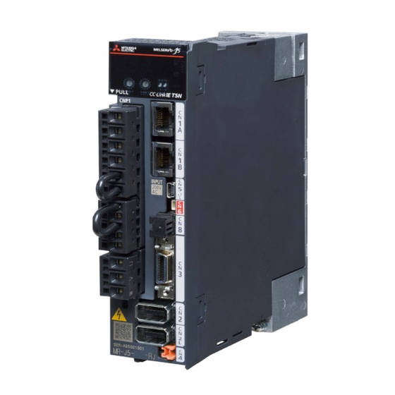
- Page 1 Mitsubishi Electric AC Servo System MR-J5 User's Manual (Hardware) -MR-J5-_G_ -MR-J5W_-_G -MR-J5-_A_...
-
Page 3: Safety Instructions
SAFETY INSTRUCTIONS (Please read the instructions carefully before using the equipment.) To use the equipment correctly, do not attempt to install, operate, maintain, or inspect the equipment until you have read through this manual, Installation guide, and appended documents carefully. Do not use the equipment until you have a full knowledge of the equipment, safety information and instructions. - Page 4 [Installation/wiring] WARNING ● To prevent an electric shock, turn off the power and wait for 15 minutes or more before starting wiring and/or inspection. ● To prevent an electric shock, ground the servo amplifier. ● To prevent an electric shock, any person who is involved in wiring should be fully competent to do the work.
-
Page 5: About The Manual
ABOUT THE MANUAL This manual covers the following servo amplifiers. • MR-J5-_G_/MR-J5W_-_G/MR-J5-_A_ In this manual, the servo amplifier names are abbreviated as shown below. Symbol Servo amplifier MR-J5-_G_ [WG] MR-J5W_-_G MR-J5-_A_ U.S. CUSTOMARY UNITS U.S. customary units are not shown in this manual. Convert the values if necessary according to the following table. Quantity SI (metric) unit U.S. -
Page 6: Table Of Contents
CONTENTS SAFETY INSTRUCTIONS..............1 ABOUT THE MANUAL . - Page 7 Detailed explanation of interfaces ............76 Source I/O interface.
- Page 8 Simple converter standard specifications ........... . . 149 External interface.
- Page 9 Residual risks of the STO function ............216 Specifications .
- Page 10 Magnetic pole detection..............270 10.3 Startup [A] .
-
Page 11: Chapter 1 Introduction
INTRODUCTION Precautions • The MR-J5-_A_-RJ and MR-J5-_G_-RJ will be available in the future. Wiring procedure Procedure Description Reference Installation Page 14 INSTALLATION Install a servo amplifier. Connection of power circuit Page 22 Connection Connect the power circuit. example of power circuit Connection of I/O signals Connect I/O signals. -
Page 12: Wiring Check
Wiring check Power supply system wiring Before switching on the main circuit and control circuit power supplies, check the following items. Power supply system wiring • The power supplied to the power input terminals (L1/L2/L3/L11/L21) of the servo amplifier should satisfy the defined specifications. - Page 13 Connection of servo amplifier and servo motor • The phases (U/V/W) of the servo amplifier power outputs and the phases (U/V/W) of the servo motor power inputs should match with each other. ■MR-J5-_G_/MR-J5-_A_ Servo amplifier Servo motor ■MR-J5W_-_G Servo amplifier A-axis servo motor CNP3A B-axis servo motor...
-
Page 14: I/O Signal Wiring
Using options or peripheral equipment ■Regenerative option • The lead wire between the P+ terminal and D terminal should not be connected. • The wires of the regenerative option should be connected to the P+ terminal and C terminal. • Twisted wires should be used for connecting the regenerative option to the servo amplifier. Page 144 Connection of regenerative option ■Simple converter •... -
Page 15: Surrounding Environment
Surrounding environment Handling cables • The wiring cables should not be stressed. • The encoder cable should be used within its bending life. Page 127 Cable bending life • The connector of the servo motor should not be stressed. Environment Signal cables and power cables should not be shorted by wire offcuts, metallic dust or the like. -
Page 16: Chapter 2 Installation
INSTALLATION Precautions • Install the servo amplifier and regenerative resistor on incombustible material. Installing them directly or close to combustibles will lead to smoke or a fire. In addition, the servo amplifier must be installed in a metal cabinet. • Provide an adequate protection to prevent screws and other conductive matter, oil and other combustible matter from entering the servo amplifier. - Page 17 Installation clearances of the servo amplifier [G] [A] ■Installation of one servo amplifier Cabinet Cabinet 40 mm or more Wiring allowance Servo amplifier 80 mm or more 10 mm 10 mm or more or more Bottom 40 mm or more ■Installation of two or more servo amplifiers Maintain a large clearance above the servo amplifier, and install a cooling fan to prevent the temperature inside the cabinet from exceeding the temperature specified in the environmental conditions.
- Page 18 Precautions • For whether close mounting is possible, refer to "Servo amplifier standard specifications" in the following manuals. MR-J5-G/MR-J5W-G User's Manual (Introduction) MR-J5-A User's Manual (Introduction) • When closely mounting multiple servo amplifiers, the servo amplifier on the right must have a larger depth than that on the left.
-
Page 19: Keeping Out Of Foreign Materials
Others When using heat generating equipment such as the regenerative option, install it with full consideration of heat generation so that the servo amplifier is not affected. Mount the servo amplifier on a perpendicular wall in the correct vertical direction. Keeping out of foreign materials When drilling the cabinet for assembly, prevent drill chips and wire fragments from entering the servo amplifier. -
Page 20: Fan Removal Procedure
Fan removal procedure Remove the screws that fixed the fan unit. Pull up the cover of the fan unit using a precision driver. Pull out the fan unit vertically. 2 INSTALLATION 2.4 Fan replacement procedure... -
Page 21: Fan Installation Procedure
Fan installation procedure Insert the positioning part of the fan unit vertically, align it to the positioning part of the main unit case, and tighten with screws. Use the same screws as those used for the fan unit before replacement. Restrictions when using this product at altitude exceeding 1000 m and up to 2000 m Effective load ratio and regenerative load ratio... - Page 22 Parts having life ■Smoothing capacitor The capacitor will reach the end of its life in 10 years of continuous operation in air-conditioned environment (ambient temperature of 30 ˚C or less). ■Relays There is no restriction. Use in the same manner as in 1000 m or less. MR-J5-G/MR-J5W-G User's Manual (Introduction) MR-J5-A User's Manual (Introduction) ■Servo amplifier cooling fan...
-
Page 23: Chapter 3 Signals And Wiring
SIGNALS AND WIRING Precautions • When using a linear servo motor, replace the wording of the sentence as follows. Load to motor inertia ratio Load to motor mass ratio Torque Thrust • Insulate the conductive parts of the terminals. •... -
Page 24: Connection Example Of Power Circuit
Connection example of power circuit Precautions • Connect a magnetic contactor between a power supply and the main circuit power supply (L1/L2/L3) of a servo amplifier to configure a circuit that shuts off the power supply on the servo amplifier side because failure of the servo amplifier may cause smoke and fire if a magnetic contactor is not connected. -
Page 25: 200 V Class
200 V class For 3-phase 200 V AC to 240 V AC power supply [G] [A] Malfunction Emergency stop switch Servo amplifier Servo motor CNP1 MCCB CNP3 3-phase 200 V AC to Motor 240 V AC CNP2 Encoder *1 P3 and P4 are connected as a factory setting. If using a power factor improving DC reactor and a simple converter, remove the short bar between P3 and P4, and then connect the reactor and converter. - Page 26 For 3-phase 200 V AC to 240 V AC power supply [WG] AND malfunction Emergency stop switch Servo amplifier A-axis servo motor CNP1 MCCB CNP3A Power Motor supply CN2A Encoder CNP2 PE ( B-axis servo motor CNP3B Motor CN2B Encoder C-axis servo motor CNP3C Motor...
- Page 27 *1 P+ and D are connected as a factory setting. If using a regenerative option, refer to the following. Page 136 Regenerative option *2 Option cables are recommended for servo motor power cables and encoder cables. Refer to the following for selecting the cables. Rotary Servo Motor User's Manual (HK series) *3 This circuit is a connection example of stopping all axes when an alarm occurs.
-
Page 28: Using Servo Amplifier With Dc Power Supply Input
Using servo amplifier with DC power supply input Connection example Refer to the following for the signals and wiring not described in this section. Page 23 200 V class ■MR-J5-10_ to MR-J5-100_/MR-J5W2-22G/MR-J5W2-44G/MR-J5W3-222G Malfunction Emergency stop switch Servo amplifier *3*4 24 V DC MCCB AC/DC 3-phase or 1-phase... - Page 29 *1 For the power supply specifications, refer to "Servo amplifier standard specifications" in the following user's manuals. MR-J5-G/MR-J5W-G User's Manual (Introduction) MR-J5-A User's Manual (Introduction) *2 Use a magnetic contactor with an operation delay time (interval between current being applied to the coil until closure of contacts) of 80 ms or less (160 ms or less for 5 kW or more).
-
Page 30: I/O Signal Connection Example
I/O signal connection example Precautions • The CN1A connector and CN1B connector are designed for CC-Link IE TSN only. Do not connect these connectors to other than CC-Link IE TSN. Otherwise, a malfunction may occur. • In the torque mode, EM2 functions the same as EM1. For MR-J5-_G_ For sink I/O interface Servo amplifier... - Page 31 *1 To prevent an electric shock, connect the protective earth (PE) terminal (the terminal marked with the symbol) of the servo amplifier to the protective earth (PE) of the cabinet. *2 Connect the diode in the correct direction. If it is connected reversely, the servo amplifier may malfunction and not output signals, disabling protective circuits such as EM2 (Forced stop 2).
-
Page 32: For Mr-J5-_A
For MR-J5-_A_ Position control mode ■For sink I/O interface Servo amplifier 24 V DC 10 m or less Positioning module RD75D/LD75D/QD75D 24 V DC DICOM DOCOM CLEARCOM DOCOM Malfunction CLEAR RDYCOM Zero speed detection READY Limiting torque PULSE F+ PULSE F- In-position PULSE R+ PULSE R-... - Page 33 *1 To prevent an electric shock, connect the protective earth (PE) terminal (the terminal marked with the symbol) of the servo amplifier to the protective earth (PE) of the cabinet. *2 Connect the diode in the correct direction. If it is connected reversely, the servo amplifier may malfunction and not output signals, disabling protective circuits such as EM2 (Forced stop 2).
- Page 34 ■For source I/O interface Precautions • For notes, refer to the notes in the following section. Page 30 For sink I/O interface Servo amplifier 24 V DC 10 m or less Positioning module RD75D/LD75D/QD75D 24 V DC DICOM DOCOM CLEAR DOCOM Malfunction CLEARCOM...
- Page 35 Speed control mode ■For sink I/O interface Servo amplifier 10 m or less 10 m or less Main circuit power supply 24 V DC *3*5 Forced stop 2 DOCOM Servo-on DOCOM Reset Speed selection 1 Malfunction Speed selection 2 Zero speed detection Forward rotation start Reverse rotation start Limiting torque...
- Page 36 ■For source I/O interface Precautions • For notes, refer to the notes in the following section. Page 33 For sink I/O interface Servo amplifier 10 m or less 10 m or less Main circuit power supply 24 V DC *3*5 Forced stop 2 DOCOM Servo-on...
- Page 37 Torque control mode ■For sink I/O interface Servo amplifier 10 m or less 10 m or less Main circuit power supply 24 V DC Forced stop 2 DOCOM Servo-on DOCOM Reset Speed selection 1 Malfunction Speed selection 2 Zero speed detection Forward rotation selection Reverse rotation selection Limiting speed...
- Page 38 ■For source I/O interface Precautions • For notes, refer to the notes in the following section. Page 35 For sink I/O interface Servo amplifier 10 m or less 10 m or less Main circuit power supply 24 V DC Forced stop 2 DOCOM Servo-on DOCOM...
-
Page 39: For Mr-J5W_-_G
For MR-J5W_-_G Precautions • In the torque control mode, EM2 functions the same as EM1. For sink I/O interface 10 m or less 10 m or less Main circuit power supply Servo amplifier 24 V DC 24 V DC DICOM DOCOM *3*4 Forced stop 2... - Page 40 *1 To prevent an electric shock, connect the protective earth (PE) terminal (the terminal marked with the symbol) of the servo amplifier to the protective earth (PE) of the cabinet. *2 Connect the diode in the correct direction. If it is connected reversely, the servo amplifier may malfunction and not output signals, disabling protective circuits such as EM2 (Forced stop 2).
- Page 41 For source I/O interface Precautions • For notes, refer to the notes in the following section. Page 37 For sink I/O interface 10 m or less 10 m or less Main circuit power supply Servo amplifier 24 V DC 24 V DC DICOM DOCOM *3*4...
-
Page 42: Explanation Of Power Supply System
Explanation of power supply system Signal explanation • For the layout of connectors and terminal blocks, refer to the following. Page 85 DIMENSIONS • If using the MR-J5 servo amplifier with the DC power supply input, refer to the following. Page 26 Using servo amplifier with DC power supply input L1/L2/L3 (Connection destination: Main circuit power supply) Supply the following power to L1, L2, and L3. - Page 43 U/V/W (Connection destination: Servo motor power supply) To prevent abnormal operation and malfunction, connect the servo amplifier power outputs (U/V/W) to the servo motor power inputs (U/V/W) directly. Do not connect a magnetic contactor and others between them. N- (Connection destination: Simple converter) This terminal is used to connect a servo amplifier with a power regeneration converter, power regeneration common converter, brake unit, or simple converter.
-
Page 44: Power-On Procedure [G] [Wg]
Power-on procedure [G] [WG] Output signals or others may be unstable at power-on. Power-on procedure Wire the power supply using a magnetic contactor between the power supply and the main circuit power supply (L1/L2/ L3) of a servo amplifier by referring to the following section. Switch off the magnetic contactor as soon as an alarm occurs. -
Page 45: Power-On Procedure [A]
Power-on procedure [A] The voltage of analog monitor output, the output signal, or others may be unstable at power-on. Power-on procedure Wire the power supply using a magnetic contactor between the power supply and the main circuit power supply (L1/L2/ L3) of a servo amplifier by referring to the following section. -
Page 46: Wiring Cnp1, Cnp2, And Cnp3
Wiring CNP1, CNP2, and CNP3 • For the wire sizes used for wiring, refer to the following. Page 166 Selection example of wires • When wiring, remove the power connectors from the servo amplifier. • Insert only one wire or ferrule into each wire insertion hole on the power connectors. To wire to CNP1, CNP2 and CNP3, use the servo amplifier power connectors that came with the amplifier. - Page 47 ■MR-J5W2-22G to MR-J5W2-1010G and MR-J5W3-222G to MR-J5W3-444G CNP1 CNP2 CNP3A CNP3B CNP3C *1 This is for the MR-J5W3-_G servo amplifier. Connector Receptacle assembly Applicable wire Stripped length Open tool Manufac [mm] turer Size Insulator OD CNP1 06JFAT-SAXGDK-K7.5 (LB) AWG 18 to 14 3.9 mm or shorter J-FAT-OT-K CNP2...
- Page 48 Connecting wires ■Fabricating wire insulator Refer to the following for the stripped length of the wire insulator. Set the appropriate length based on the wire type and fabrication condition. Page 44 Connector Insulator Core Stripped length Twist the core wires lightly and straighten them as follows. Loose and bent strands Twist and straighten the strands.
-
Page 49: Connectors And Pin Assignments
Connectors and pin assignments • The pin assignments of the connectors are as viewed from the cable connector wiring section. • For the STO I/O signal connector (CN8), refer to the following. Page 215 USING STO FUNCTION [G] [A] • For wiring to the I/O signal connector (CN3), securely connect the external conductor of the shielded cable to the ground plate and fix it to the connector shell. -
Page 50: Connectors And Pin Assignment [G]
Connectors and pin assignment [G] The front view of the servo amplifier shown below is of MR-J5-_G-RJ servo amplifiers with a rated capacity symbol of 60 or less. Refer to the following for the appearance and connector layout of the other servo amplifiers. Page 85 DIMENSIONS The frames of the CN2 connector, CN2L connector, and CN3 connector are connected to the protective earth (grounding) terminal in the servo amplifier. -
Page 51: Connectors And Pin Assignment [A]
Connectors and pin assignment [A] The front view of the servo amplifier shown below is of MR-J5-_A-RJ servo amplifiers with a rated capacity symbol of 60 or less. Refer to the following for the appearances and connector layouts of the other servo amplifiers. Page 85 DIMENSIONS The frames of the CN2 connector, CN2L connector, and CN3 connector are connected to the protective earth (grounding) terminal in the servo amplifier. - Page 52 Initial assignment of CN3 connector pins Pin No. I/O signal in each control mode Related servo parameter P15R P15R P15R P15R P15R P15R -/VC VC/VLA VLA/- PP/- -/PP ...
- Page 53 *1 I: input signal, O: output signal *2 P: position control mode, S: speed control mode, T: torque control mode, P/S: position/speed control switching mode, S/T: speed/torque control switching mode, T/P: torque/position control switching mode *3 Output devices are not assigned by default. Assign the output devices with [Pr. PD47] as necessary. This pin is available only with MR- J5-_A_-RJ.
-
Page 54: Connectors And Pin Assignment [Wg]
Connectors and pin assignment [WG] The front view of the servo amplifier shown below is of the MR-J5W3-222G. Refer to the following for the appearance and connector layout of the other servo amplifiers. Page 85 DIMENSIONS The frames of the CN2A connector, CN2B connector, CN2C connector, and CN3 connector are connected to the protective earth (grounding) terminal in the servo amplifier. -
Page 55: Signal (Device) Explanation
Signal (device) explanation For the I/O interfaces (symbols in the I/O division column in the table), refer to the following. Page 76 Detailed explanation of interfaces The pin numbers in the connector pin No. column are default numbers. and in the table show the following. : Usable device as a factory setting : Device becomes available by setting a servo parameter MR-J5-G/MR-J5W-G User's Manual (Parameters) - Page 56 Input devices Device name Symbol Model I/O signal Detailed interface type explanation [G] [WG] Page 55 Forced stop 2 DI-1 EM2 (Forced stop 2) Page 55 Forced stop 1 DI-1 EM1 (Forced stop 1) ...
- Page 57 Device name Symbol Model I/O signal Detailed interface type explanation [G] [WG] Control switching DI-1 Page 59 LOP (Control switching) Page 59 Second STAB2 DI-1 acceleration/ STAB2 (Second deceleration acceleration/ selection deceleration selection) ...
- Page 58 ■LSP (Forward rotation stroke end)/LSN (Reverse rotation stroke end) To operate a servo motor, turn on LSP/LSN. Turn LSP/LSN off to bring the servo motor to a stop and make it in the servo-lock state. For information such as the supported control modes, automatic on, and restrictions, refer to "Stroke limit function" in the following user's manual.
- Page 59 ■TL (External torque limit selection) When TL is off, [Pr. PA11] and [Pr. PA12] are enabled. When TL is on, TLA (Analog torque limit) is enabled. Refer to the following for details. MR-J5 User's Manual (Function) ■TL1 (Internal torque limit selection) When TL1 is on, [Pr.
- Page 60 ■SP1 (Speed selection 1)/SP2 (Speed selection 2)/SP3 (Speed selection 3) • For speed control mode Select the command speed for operation. The selection contents are as follows. Input device Speed command 0 (off) 0 (off) 0 (off) VC (Analog speed command) 0 (off) 0 (off) 1 (on)
- Page 61 ■LOP (Control switching) • Position/speed control switching mode This is used to select the position control mode or the speed control mode in the position/speed control switching mode. Control mode 0 (off) Position control mode 1 (on) Speed control mode •...
-
Page 62: Output Device
Output device Output device pins The following shows the output device pins and servo parameters for assigning devices. ■MR-J5-_G_ Connector pin No. Servo parameter Initially assigned device I/O signal interface type CN3-13 [Pr. PD07] DO-1 CN3-9 [Pr. PD08] CN3-15 [Pr. PD09] ■MR-J5W2-_G Connector pin No. - Page 63 Device name Symbol Model I/O signal Detailed interface type explanation Variable gain CDPS2 DO-1 Page 62 selection 2 CDPS2 (Variable gain selection 2) Page 62 Absolute position ABSV DO-1 undetermined ABSV (Absolute position undetermined) During tough...
- Page 64 ■SA (Speed reached) At servo-off, SA is off. When the servo motor speed reaches the following range, SA turns on. Set speed ((Set speed 0.05) + 20) r/min (mm/s) When the set speed is 20 r/min or less, SA is always on. The device cannot be used in the position mode and torque mode.
- Page 65 ■ZSP (Zero speed detection) If the servo motor speed is zero speed or less, ZSP will turn on. Zero speed can be changed with [Pr. PC07]. OFF level 70 r/min 20 r/min (Hysteresis width) ON level 50 r/min [Pr. PC07] Servo motor 0 r/min speed...
- Page 66 ■ZSP (Zero speed detection) If the servo motor speed is zero speed or less, ZSP will turn on. Zero speed can be changed with [Pr. PC17]. OFF level 70 r/min 20 r/min (Hysteresis width) ON level 50 r/min [Pr. PC17] Servo motor 0 r/min speed...
-
Page 67: Input Signal
■ALMWNG (Malfunction/Warning) When an alarm occurs, ALMWNG turns off. When a warning occurs (except for [AL. 09F Battery warning]), ALMWNG turns on and off repeatedly approximately every 1 s. When neither an alarm nor a warning is occurring, ALMWNG will turn on in 2.5 s to 3.5 s after power-on. ■BW9F (AL9F warning) When [AL. - Page 68 ■VLA (Analog speed limit) Apply 0 V DC to ±10 V DC between VLA and LG. At ±10 V, the servo motor speed is the value set in [Pr. PC12]. Refer to the following for details. MR-J5 User's Manual (Function) If a value equal to or larger than the maximum speed is input to VLA, the value is clamped at the maximum speed.
-
Page 69: Output Signal
Output signal Output signal explanation ■LA/LAR (Encoder A-phase pulse (differential line driver))/LB/LBR (Encoder B-phase pulse (differential line driver)) These devices output encoder output pulses set in [Pr. PA15] and [Pr. PA16] in the differential line driver type. When the servo motor rotates in the CCW direction, the encoder B-phase pulse lags the encoder A-phase pulse by a phase of 90 degrees. -
Page 70: Power Supply
Power supply Power supply explanations ■DICOM (Digital I/F power supply input) Input 24 V DC (24 V DC 10 %) for I/O interface. The power supply capacity varies depending on the number of I/O interface points to be used. It is 300 mA for the MR-J5-_G_, and it is 500 mA for the MR-J5-_A_. For sink interface, connect the positive terminal of the 24 V DC external power supply. -
Page 71: Interface
Interface Internal connection diagram [G] Refer to the following for the CN8 connector. Page 215 USING STO FUNCTION [G] [A] Servo amplifier Forced stop 24 V DC Approx. 6.2 kΩ DOCOM Approx. 6.2 kΩ DICOM 24 V DC Isolated Analog monitor DC ±... -
Page 72: Internal Connection Diagram [A]
Internal connection diagram [A] Refer to the following for the CN8 connector. Page 215 USING STO FUNCTION [G] [A] 3 SIGNALS AND WIRING 3.6 Interface... - Page 73 Servo amplifier 24 V DC Approx. 6.2 kΩ SON SON SON DOCOM SP2 SP2 DOCOM ST1 RS2 ST2 RS1 RES RES Approx. 6.2 kΩ DICOM *7*8 24 V DC DICOM *7*8 Approx. 100 Ω Approx. 1.2 kΩ Approx. 1.2 kΩ Approx.
- Page 74 *1 P: position control mode, S: speed control mode, T: torque control mode *2 This is for the differential line driver pulse train input. For the open-collector pulse train input, connect as follows. DOCOM DOCOM 24 V DC 24 V DC DICOM DICOM DOCOM...
-
Page 75: Internal Connection Diagram [Wg]
Internal connection diagram [WG] Refer to the following for the CN8 connector. Page 215 USING STO FUNCTION [G] [A] 3 SIGNALS AND WIRING 3.6 Interface... - Page 76 Servo amplifier 24 V DC DOCOM 24 V DC MBR-A DICOM Approx. 5.6 kΩ MBR-B DI1-A MBR-C CALM DI2-A DI3-A DI1-B DI2-B Analog monitor DI3-B DI1-C DC ± 10 V DC ± 10 V DI2-C Approx. 5.6 kΩ DI3-C LA-A LAR-A LB-A LBR-A...
- Page 77 *1 You can assign signals to these pins with servo parameters ([Pr. PD03] to [Pr. PD05]). *2 This diagram shows a sink I/O interface. For the source I/O interface, refer to the following. Page 80 Source I/O interface *3 This is for the MR-J5W3-_G servo amplifier. *4 In the initial setting, CINP (AND in-position) is assigned to this pin.
-
Page 78: Detailed Explanation Of Interfaces
Detailed explanation of interfaces The details of I/O signal interfaces stated in the following section (refer to the I/O signal interface type in the table) are as follows. Refer to the section and connect them with external devices. Page 53 Signal (device) explanation Digital input interface DI-1 This is an input circuit in which the photocoupler cathode side is the input terminal. - Page 79 Digital output interface DO-1 This is a circuit in which the collector of the output transistor is the output terminal. When the output transistor is turned on, the current flows to the collector terminal. A lamp, relay, or photocoupler can be driven. Install a diode (D) for an inductive load, or install an inrush current suppressing resistor (R) for a lamp load.
- Page 80 ■Open-collector type • Interface Servo amplifier Max. input pulse 24 V DC frequency 200 kpulses/s Approx. 1.2 kΩ 2 m or less PP, NP DOCOM *1 A photocoupler is used as the pulse train input interface. Therefore this circuit may not operate properly due to reduction in current if a resistor is connected to the pulse train signal line.
- Page 81 ■Open-collector type • Interface Maximum output current: 35 mA 5 V DC to 24 V Servo amplifier Servo amplifier Photocoupler Analog input AI-1 Input impedance 10 kΩ to 12 kΩ Servo amplifier DC + 15 V P15R Upper limit setting: 2 kΩ etc.
-
Page 82: Source I/O Interface
Source I/O interface For the servo amplifiers in this manual, source type I/O interfaces can be used. Digital input interface DI-1 This is an input circuit in which the anode of the photocoupler is the input terminal. Transmit signals from source (open- collector) type transistor output, a relay switch, or others. - Page 83 Pulse train input interface DI-2 [A] Transmit a pulse train signal in the open-collector type. • Interface Servo amplifier Max. input pulse frequency 200 kpulses/s Approx. 20 mA ≤ 1.0 V Approx. 1.2 kΩ ≤ 100 μA Approx. 20 mA ≤...
-
Page 84: Servo Motor With An Electromagnetic Brake
Servo motor with an electromagnetic brake Precautions • For specifications such as the power supply capacity and operation delay time of the electromagnetic brake, and for selecting the surge absorber for the electromagnetic brake, refer to the following. Rotary Servo Motor User's Manual (HK series) •... - Page 85 Connection diagram [WG] A-axis servo motor CALM MBR-A Servo amplifier 24 V DC 24 V DC for DOCOM electromagnetic brake DICOM CALM 24 V DC MBR-A MBR-B B-axis servo motor MBR-B MBR-C C-axis servo motor MBR-C *1 Do not share the 24 V DC power supply for interface with the electromagnetic brake. *2 Configure a circuit which interlocks with an emergency stop switch to shut off.
-
Page 86: Grounding
Grounding The servo amplifier supplies power to the servo motor by switching on and off a power transistor. Depending on the wiring and ground wire routing, the servo amplifier may be affected by the switching noise (due to di/dt and dv/dt) of the transistor. To prevent such a fault, refer to the following diagram and ground it. -
Page 87: Chapter 4 Dimensions
DIMENSIONS 200 V class MR-J5-10G_/MR-J5-20G_/MR-J5-40G_ Approx. 40 Terminal assignment φ6 mounting Approx. 6 2-M5 screw CNP1 CNP2 CNP3 Approx. 80 hole CNP1 CN1A CN1B CNP2 CNP3 Screw size CN2L Mounting screw size Mounting hole process drawing Approx. 38.5 MR-J5-60G_ Approx. 40 Terminal assignment φ6 mounting Approx. -
Page 88: Mr-J5-70G_/Mr-J5-100G
MR-J5-70G_/MR-J5-100G_ Terminal assignment φ6 mounting CNP1 CNP2 CNP3 Approx. 80 hole Approx. 60 Exhaust Cooling fan CNP1 CN1A CN1B CNP2 CNP3 Screw size CN2L 3-M5 screw Mounting screw size Intake Approx. 12 Approx. 6 42 ± 0.3 Mounting hole process drawing MR-J5-200G_/MR-J5-350G_ Terminal assignment φ6 mounting... -
Page 89: Mr-J5-10A_/Mr-J5-20A_/Mr-J5-40A
MR-J5-10A_/MR-J5-20A_/MR-J5-40A_ Approx. 40 Terminal assignment φ6 mounting Approx. 6 2-M5 screw CNP1 CNP2 CNP3 hole Approx. 80 CNP1 CN1A CNP2 CNP3 Screw size CN2L Mounting screw size Mounting hole process drawing Approx. 38.5 MR-J5-60A_ Approx. 40 Terminal assignment φ6 mounting Approx. -
Page 90: Mr-J5-200A_/Mr-J5-350A
MR-J5-200A_/MR-J5-350A_ Terminal assignment φ6 mounting Approx. 80 Approx. 90 CNP1 CNP2 CNP3 hole Cooling Exhaust CNP1 CN1A CNP2 CNP3 Screw size CN2L 3-M5 screw Mounting screw size Intake Approx. 6 Approx. 6 78 ± 0.3 Mounting hole process drawing MR-J5W2-22G/MR-J5W2-44G Terminal assignment φ6 mounting Approx. -
Page 91: Mr-J5W2-77G/Mr-J5W2-1010G
MR-J5W2-77G/MR-J5W2-1010G Terminal assignment φ6 mounting CNP1 CNP2 CNP3A hole Approx. 85 Approx. 80 Cooling Exhaust CNP1 CNP3B CN1A CN1B CNP2 CNP3A CNP3B Screw size CN2A CN2B 3-M5 screw Mounting screw size Intake Approx. 6 73 ± 0.3 Mounting hole process drawing MR-J5W3-222G/MR-J5W3-444G Terminal assignment φ6 mounting... -
Page 92: Connector
Connector Precautions • Obtain the wiring instructions from the manufacturer and wire connectors appropriately. CN3 connector [G] Miniature delta ribbon (MDR) system (3M) ■One-touch lock type [Unit: mm] Logo or others are indicated here. 12.7 Connector Shell kit Variable dimensions 10120-3000PE 10320-52F0-008 22.0... -
Page 93: Cn3 Connector [A]
CN3 connector [A] Miniature delta ribbon (MDR) system (3M) ■One-touch lock type [Unit: mm] Logo or others are indicated here. 12.7 Connector Shell kit Variable dimensions 10150-3000PE 10350-52F0-008 41.1 52.4 18.0 14.0 17.0 ■Jack screw M2.6 type This connector is not available as an option. [Unit: mm] Logo or others are indicated here. -
Page 94: Cn3_ Connector [Wg]
CN3_ connector [WG] Miniature delta ribbon (MDR) system (3M) ■One-touch lock type [Unit: mm] Logo or others are indicated here. 12.7 Connector Shell kit Variable dimensions 10126-3000PE 10326-52F0-008 25.8 37.2 14.0 10.0 12.0 ■Jack screw M2.6 type This connector is not available as an option. [Unit: mm] Logo or others are indicated here. - Page 95 SCR connector system (3M) Receptacle: 36210-0100PL Shell kit: 36310-3200-008 [Unit: mm] 39.5 34.8 4 DIMENSIONS 4.4 CN3_ connector [WG]...
-
Page 96: Chapter 5 Characteristics
CHARACTERISTICS For the characteristics of the linear servo motor and the direct drive motor, refer to the following. Page 262 Characteristics Page 289 Characteristics Overload protection characteristics An electronic thermal is built in the servo amplifier to protect the servo motor, servo amplifier and servo motor power wires from overloads. - Page 97 ■MR-J5-20_/MR-J5W2-22G/MR-J5W3-222G 1000 Output current [Arms] ■MR-J5-40_/MR-J5W2-44G/MR-J5W3-444G 1000 Output current [Arms] ■MR-J5-60_ 1000 Output current [Arms] ■MR-J5-70_/MR-J5W2-77G 1000 Output current [Arms] 5 CHARACTERISTICS 5.1 Overload protection characteristics...
- Page 98 ■MR-J5-100_/MR-J5W2-1010G 1000 Output current [Arms] ■MR-J5-200_ 1000 Output current [Arms] ■MR-J5-350_ 1000 Output current [Arms] 5 CHARACTERISTICS 5.1 Overload protection characteristics...
-
Page 99: Power Supply Capacity And Generated Loss
Power supply capacity and generated loss Power supply capacity The following table indicates power supply capacities of servo amplifiers. When the servo motor runs at less than the rated speed, the power supply capacity is smaller than the value in the table. 1-axis servo amplifiers Rotary servo motor Servo amplifier... - Page 100 Rotary servo motor Servo amplifier Power supply capacity [kVA] HK-KT series (Standard voltage: 200 V) HK-KT203W MR-J5-200G/A MR-J5-350G/A HK-KT202W MR-J5-200G/A MR-J5-350G/A HK-KT series (Standard voltage: 400 V) HK-KT434W MR-J5-20G/A MR-J5-40G/A MR-J5-60G/A HK-KT634W MR-J5-40G/A MR-J5-60G/A MR-J5-70G/A HK-KT7M34W MR-J5-40G/A MR-J5-60G/A MR-J5-70G/A HK-KT1034W MR-J5-60G/A MR-J5-70G/A MR-J5-100G/A...
- Page 101 Rotary servo motor Servo amplifier Power supply capacity [kVA] HK-ST series (Standard voltage: 400 V) HK-ST3024W MR-J5-200G/A MR-J5-350G/A HK-ST2024W MR-J5-200G/A MR-J5-350G/A HK-ST3524W MR-J5-200G/A MR-J5-350G/A HK-ST5024W MR-J5-350G/A *1 The power supply capacity will vary according to the power impedance. Multi-axis servo amplifiers Rotary servo motor Servo amplifier Power supply capacity [kVA]...
- Page 102 Rotary servo motor Servo amplifier Power supply capacity [kVA] HK-KT series (Standard voltage: 400 V) HK-KT434W MR-J5W2-22G MR-J5W2-44G MR-J5W3-222G MR-J5W3-444G HK-KT634W MR-J5W2-44G MR-J5W2-77G MR-J5W2-1010G MR-J5W3-444G HK-KT7M34W MR-J5W2-44G MR-J5W2-77G MR-J5W2-1010G MR-J5W3-444G HK-KT1034W MR-J5W2-77G MR-J5W2-1010G HK-KT1534W MR-J5W2-77G MR-J5W2-1010G HK-KT2034W MR-J5W2-1010G HK-KT2024W MR-J5W2-1010G HK-ST series (Standard voltage: 200 V) HK-ST52W MR-J5W2-77G...
-
Page 103: Generated Loss
Generated loss Servo amplifier generated heat The following tables indicate the losses generated by servo amplifiers under rated load. For thermal design of an enclosed type cabinet, use the values in the tables in consideration for the worst operating conditions. The actual amount of generated heat will be intermediate between values at rated output and servo-off according to the duty used during operation. -
Page 104: When Using The Servo Amplifier With The Dc Power Supply Input
Heat dissipation area for enclosed type cabinet The enclosed type cabinet (hereafter called the cabinet) that will stores the servo amplifier should be designed to ensure that its internal temperature rise is within +15 °C at an ambient temperature of 40 °C. Calculate the necessary cabinet dissipation area with equation (10.1), allowing a margin of approximately 5 °C for the ambient temperature of 60 °C maximum. -
Page 105: Dynamic Brake Characteristics
Dynamic brake characteristics • The coasting distance is a theoretically calculated value that does not consider factors such as friction. If the braking distance is not longer than the calculated value, a moving part may crash into the stroke end. Install an anti-crash mechanism such as an air brake or an electric/mechanical stopper such as a shock absorber to reduce the shock of moving parts. -
Page 106: Dynamic Brake Operation
Dynamic brake operation Calculation of coasting distance The following figure shows the pattern in which the servo motor comes to a stop when the dynamic brake is operated. Use equation (10.2) to calculate the approximate coasting distance to a stop. The dynamic brake time constant τ varies with the servo motor and machine operation speeds. - Page 107 Dynamic brake time constant The following shows necessary dynamic brake time constant τ for equation (10.2). Motor Amplifier Waveform HK-KT053W MR-J5-10_ MR-J5-20_ MR-J5-40_ MR-J5W2-22G MR-J5W2-44G MR-J5W3-222G MR-J5W3-444G 2000 4000 6000 8000 Servo motor speed [r/min] HK-KT13W MR-J5-10_ MR-J5-20_ MR-J5-40_ MR-J5W2-22G MR-J5W2-44G MR-J5W3-222G MR-J5W3-444G...
- Page 108 Motor Amplifier Waveform HK-KT23W MR-J5-20_ MR-J5-40_ MR-J5-60_ MR-J5W2-22G MR-J5W2-44G MR-J5W3-222G MR-J5W3-444G 2000 4000 6000 8000 Servo motor speed [r/min] HK-KT43W MR-J5-40_ MR-J5-60_ MR-J5W2-44G MR-J5W3-444G 2000 4000 6000 8000 Servo motor speed [r/min] MR-J5-70_ MR-J5W2-77G 2000 4000 6000 8000 Servo motor speed [r/min] MR-J5W2-1010G 2000 4000...
- Page 109 Motor Amplifier Waveform HK-KT63W MR-J5-70_ MR-J5W2-77G 2000 4000 6000 8000 Servo motor speed [r/min] MR-J5-100_ MR-J5W2-1010G 22.5 21.5 20.5 19.5 2000 4000 6000 8000 Servo motor speed [r/min] MR-J5-200_ 2000 4000 6000 8000 Servo motor speed [r/min] HK-KT23UW MR-J5-20_ MR-J5-40_ MR-J5-60_ MR-J5W2-22G MR-J5W2-44G...
- Page 110 Motor Amplifier Waveform HK-KT43UW MR-J5-40_ MR-J5-60_ MR-J5W2-44G MR-J5W3-444G 2000 4000 6000 8000 Servo motor speed [r/min] MR-J5-70_ MR-J5W2-77G MR-J5W2-1010G 2000 4000 6000 8000 Servo motor speed [r/min] 5 CHARACTERISTICS 5.3 Dynamic brake characteristics...
- Page 111 Motor Amplifier Waveform HK-KT7M3W MR-J5-70_ MR-J5W2-77G 2000 4000 6000 8000 Servo motor speed [r/min] MR-J5-100_ MR-J5W2-1010G 34.5 33.5 32.5 31.5 30.5 29.5 2000 4000 6000 8000 Servo motor speed [r/min] MR-J5-200_ 2000 4000 6000 8000 Servo motor speed [r/min] 5 CHARACTERISTICS 5.3 Dynamic brake characteristics...
- Page 112 Motor Amplifier Waveform HK-KT103W MR-J5-100_ MR-J5W2-1010G 1000 2000 3000 4000 5000 6000 7000 Servo motor speed [r/min] MR-J5-200_ MR-J5-350_ 1000 2000 3000 4000 5000 6000 7000 Servo motor speed [r/min] 5 CHARACTERISTICS 5.3 Dynamic brake characteristics...
- Page 113 Motor Amplifier Waveform HK-KT7M3UW MR-J5-70_ MR-J5W2-77G 2000 4000 6000 8000 Servo motor speed [r/min] MR-J5-100_ MR-J5W2-1010G 2000 4000 6000 8000 Servo motor speed [r/min] MR-J5-200_ 2000 4000 6000 8000 Servo motor speed [r/min] 5 CHARACTERISTICS 5.3 Dynamic brake characteristics...
- Page 114 Motor Amplifier Waveform HK-KT103UW MR-J5-100_ 41.5 MR-J5W2-1010G 40.5 39.5 38.5 37.5 36.5 1000 2000 3000 4000 5000 6000 7000 Servo motor speed [r/min] MR-J5-200_ MR-J5-350_ 1000 2000 3000 4000 5000 6000 7000 Servo motor speed [r/min] HK-KT153W MR-J5-200_ MR-J5-350_ 1000 2000 3000 4000...
- Page 115 Motor Amplifier Waveform HK-KT202W MR-J5-200_ MR-J5-350_ 1000 1500 2000 2500 3000 3500 Servo motor speed [r/min] HK-KT434W MR-J5-20_ MR-J5-40_ MR-J5-60_ MR-J5W2-22G MR-J5W2-44G MR-J5W3-222G MR-J5W3-444G 1000 2000 3000 4000 Servo motor speed [r/min] 5 CHARACTERISTICS 5.3 Dynamic brake characteristics...
- Page 116 Motor Amplifier Waveform HK-KT634W MR-J5-40_ MR-J5-60_ MR-J5W2-44G MR-J5W3-444G 1000 2000 3000 4000 Servo motor speed [r/min] MR-J5-70_ MR-J5W2-77G 1000 2000 3000 4000 Servo motor speed [r/min] MR-J5W2-1010G 1000 2000 3000 4000 Servo motor speed [r/min] 5 CHARACTERISTICS 5.3 Dynamic brake characteristics...
- Page 117 Motor Amplifier Waveform HK-KT7M34W MR-J5-40_ MR-J5-60_ MR-J5W2-44G MR-J5W3-444G 1000 2000 3000 4000 Servo motor speed [r/min] MR-J5-70_ MR-J5W2-77G 1000 2000 3000 4000 Servo motor speed [r/min] MR-J5W2-1010G 1000 2000 3000 4000 Servo motor speed [r/min] 5 CHARACTERISTICS 5.3 Dynamic brake characteristics...
- Page 118 Motor Amplifier Waveform HK-KT1034W MR-J5-60_ 1000 1500 2000 2500 3000 3500 Servo motor speed [r/min] MR-J5-70_ MR-J5W2-77G 1000 1500 2000 2500 3000 3500 Servo motor speed [r/min] MR-J5-100_ MR-J5W2-1010G 1000 1500 2000 2500 3000 3500 Servo motor speed [r/min] 5 CHARACTERISTICS 5.3 Dynamic brake characteristics...
- Page 119 Motor Amplifier Waveform HK-KT1534W MR-J5-70_ MR-J5W2-77G 1000 1500 2000 2500 3000 Servo motor speed [r/min] MR-J5-100_ MR-J5W2-1010G 15.5 14.5 13.5 1000 1500 2000 2500 3000 Servo motor speed [r/min] MR-J5-200_ 1000 1500 2000 2500 3000 Servo motor speed [r/min] 5 CHARACTERISTICS 5.3 Dynamic brake characteristics...
- Page 120 Motor Amplifier Waveform HK-KT2034W MR-J5-100_ MR-J5W2-1010G 18.8 18.6 18.4 18.2 17.8 17.6 17.4 17.2 1000 1500 2000 2500 3000 Servo motor speed [r/min] MR-J5-200_ MR-J5-350_ 1000 1500 2000 2500 3000 Servo motor speed [r/min] HK-KT2024W MR-J5-100_ MR-J5W2-1010G 12.5 12.4 12.3 12.2 12.1 11.9...
- Page 121 Motor Amplifier Waveform HK-ST52W MR-J5-60_ 1000 2000 3000 4000 5000 Servo motor speed [r/min] MR-J5-70_ MR-J5W2-77G 1000 2000 3000 4000 5000 Servo motor speed [r/min] MR-J5-100_ MR-J5W2-1010G 1000 2000 3000 4000 5000 Servo motor speed [r/min] 5 CHARACTERISTICS 5.3 Dynamic brake characteristics...
- Page 122 Motor Amplifier Waveform HK-ST102W MR-J5-100_ MR-J5W2-1010G 1000 2000 3000 4000 5000 Servo motor speed [r/min] MR-J5-200_ MR-J5-350_ 1000 2000 3000 4000 5000 Servo motor speed [r/min] HK-ST172W MR-J5-200_ MR-J5-350_ 1000 2000 3000 4000 5000 Servo motor speed [r/min] HK-ST202AW MR-J5-200_ MR-J5-350_ 1000 2000...
- Page 123 Motor Amplifier Waveform HK-ST302W MR-J5-350_ 1000 1500 2000 2500 3000 Servo motor speed [r/min] HK-ST202W MR-J5-200_ MR-J5-350_ 1000 2000 3000 4000 5000 Servo motor speed [r/min] HK-ST352W MR-J5-350_ 1000 2000 3000 4000 Servo motor speed [r/min] 5 CHARACTERISTICS 5.3 Dynamic brake characteristics...
- Page 124 Motor Amplifier Waveform HK-ST524W MR-J5-40_ MR-J5-60_ MR-J5W2-44G MR-J5W3-444G 1000 1500 2000 2500 Servo motor speed [r/min] MR-J5-70_ MR-J5W2-77G 1000 1500 2000 2500 Servo motor speed [r/min] 5 CHARACTERISTICS 5.3 Dynamic brake characteristics...
- Page 125 Motor Amplifier Waveform HK-ST1024W MR-J5-60_ 1000 1500 2000 2500 Servo motor speed [r/min] MR-J5-70_ MR-J5W2-77G 1000 1500 2000 2500 Servo motor speed [r/min] MR-J5-100_ MR-J5W2-1010G 1000 1500 2000 2500 Servo motor speed [r/min] 5 CHARACTERISTICS 5.3 Dynamic brake characteristics...
- Page 126 Motor Amplifier Waveform HK-ST1724W MR-J5-100_ MR-J5W2-1010G 1000 1500 2000 2500 Servo motor speed [r/min] MR-J5-200_ MR-J5-350_ 1000 1500 2000 2500 Servo motor speed [r/min] HK-ST2024AW MR-J5-100_ MR-J5W2-1010G 1000 1500 2000 2500 Servo motor speed [r/min] MR-J5-200_ MR-J5-350_ 1000 1500 2000 2500 Servo motor speed [r/min] 5 CHARACTERISTICS...
- Page 127 Motor Amplifier Waveform HK-ST3024W MR-J5-200_ MR-J5-350_ 1000 1200 1400 Servo motor speed [r/min] HK-ST2024W MR-J5-200_ MR-J5-350_ 1000 1500 2000 2500 Servo motor speed [r/min] HK-ST3524W MR-J5-200_ MR-J5-350_ 1000 1500 2000 Servo motor speed [r/min] HK-ST5024W MR-J5-350_ 1000 1500 2000 2500 Servo motor speed [r/min] 5 CHARACTERISTICS 5.3 Dynamic brake characteristics...
- Page 128 Permissible load to motor inertia when the dynamic brake is used Use the dynamic brake under the load to motor inertia ratio indicated in the following table. If the ratio is higher than this value, the dynamic brake may burn. If the ratio exceeds the value, contact your local sales office. The values of the permissible load to motor inertia ratio in the table are the values at the maximum speed of the servo motor.
-
Page 129: Cable Bending Life
Cable bending life The bending life of the cables is shown below. This graph shows calculated values. Since they are not guaranteed values, provide a little allowance for these values. 1 × 10 5 × 10 1 × 10 5 × 10 Long bending life encoder cable Long bending life dual cable type Long bending life single cable type... -
Page 130: Inrush Currents At Power-On Of Main Circuit And Control Circuit
Inrush currents at power-on of main circuit and control circuit Since large inrush currents flow in the power supplies, be sure to use molded-case circuit breakers and magnetic contactors. Page 168 Molded-case circuit breakers, fuses, magnetic contactors When circuit protectors are used, it is recommended that the inertia delay type, which is not tripped by an inrush current, be used. -
Page 131: Chapter 6 Options And Peripheral Equipment
OPTIONS AND PERIPHERAL EQUIPMENT Precautions • HIV wires are recommended to wire the servo amplifiers, options, and peripheral equipment. Therefore, the recommended wire sizes may differ from those used for the previous servo amplifiers. • To prevent an electric shock or a fire, correctly wire options and peripheral equipment, etc. in the correct combination. Cable/connector sets The IP rating indicated for cables and connectors is their protection against ingress of dust and water drops when they are connected to a servo amplifier or servo motor. -
Page 132: Combinations Of Cable/Connector Sets
Combinations of cable/connector sets For MR-J5-_G_ servo amplifiers CC-Link IE TSN Setup Controller Servo amplifier Servo amplifier software Ethernet cable MR Configurator2 CN1A CN1A CNP1 CNP1 CN1B CN1B (10) CC-Link IE TSN CNP2 CNP2 CNP3 CNP3 Junction terminal block PS7DW-20V14B-F (manufactured by Toho Technology Corporation) To servo motor... - Page 133 For MR-J5W-_G servo amplifiers CC-Link IE TSN Setup Controller Servo amplifier Servo amplifier software Ethernet cable MR Configurator2 CN1A CN1A CNP1 CNP1 CN1B CN1B CC-Link IE TSN CNP2 CNP2 CNP3A CNP3A CN2A CN2A CNP3B CNP3B Junction terminal block MR-TB26A CN2B CN2B CNP3C CNP3C...
- Page 134 List of cable/connector sets Product name Model Description Remark Servo amplifier Supplied with 1-axis power connector servo amplifiers of 1 kW or less CNP1 connector CNP2 connector CNP3 connector 06JFAT-SAXGDK-K7.5 05JFAT-SAXGDK-K5.0 03JFAT-SAXGDK-K7.5 (LA) (JST) (LA) (JST) (LA) (JST) Applicable wire size: Applicable wire size: Applicable wire size: 0.8 mm...
- Page 135 Product name Model Description Remark Servo amplifier Supplied with multi- power connector axis servo amplifiers of 750 W or more CNP1 connector CNP2 connector CNP3 connector 06JFAT-SAXGFK-XL 05JFAT-SAXGDK-H5.0 04JFAT-SAGG-G-KK (LB) (JST) (LA) (JST) (JST) Applicable wire size: Applicable wire size: Applicable wire size: 1.25 mm to 5.5 mm...
- Page 136 Product name Model Description Remark Junction terminal MR-TBNATBL_M For MR-J5W_-_G block cable Cable length: 0.5 m, (1) Junction terminal block connector Connector: 10126-6000EL Shell kit: 10326-3210-000 (3M or equivalent) (2) CN1 connector Connector: 10126-6000EL Shell kit: 10326-3210-000 (3M or equivalent) STO cable MR-D05UDL3M-B Connection cable for...
-
Page 137: Mr-D05Udl3M-B Sto Cable
Contact SC-E5EW(-L) Mitsubishi Electric System & Service Co., Please consult your local Mitsubishi Electric representative. Ltd. *1 The SC-E5EW cable is for in-cabinet and indoor uses. The SC-E5EW-L cable is for outdoor use. For cables other than SC-E5EW(-L), refer to the CC-Link Partner Association website (https://www.cc-link.org/en/). -
Page 138: Regenerative Option
Regenerative option Combination and regenerative power The power values in the table are resistor-generated powers and not rated powers. 200 V class Servo amplifier Regenerative power [W] Built-in MR-RB12 MR-RB14 MR-RB30 MR-RB3N MR-RB34 MR-RB50 MR-RB5N regenerative RB032 [40 Ω] [26 Ω] [13 Ω] [9 Ω] [26 Ω]... -
Page 139: Selection Of The Regenerative Option [G] [A]
Selection of the regenerative option [G] [A] A regenerative option for a horizontal axis can be selected with the rough calculation shown in this section. To select a regenerative option precisely, use the capacity selection software. Rotary servo motor ■Regenerative energy calculation Servo motor Feed speed of moving part Forward... - Page 140 *1*2 Regenerative Torque applied to servo motor [N•m] Energy E [J] power /η + J ) • N 0.1047 • • N • T • t psa1 9.55 • 10 psa1 = 0.1047 • N • T • t • η + J ) •...
- Page 141 For linear servo motors ■Thrust and energy calculation Linear servo motor Linear servo motor feed speed secondary side (magnet) Load Positive direction Time Negative Linear servo motor direction primary side (coil) Linear servo motor psa1 psd1 psa2 psd2 The following shows formulas of the linear servo motor thrust and energy at the operation pattern above. Section Thrust F of linear servo motor [N] Energy E [J]...
-
Page 142: Selection Of The Regenerative Option [Wg]
Selection of the regenerative option [WG] A regenerative option for a horizontal axis can be selected with the rough calculation shown in this section. To select a regenerative option precisely, use the capacity selection software. Rotary servo motor ■Regenerative energy calculation Servo motor Feed speed of moving part Forward... - Page 143 *1*2 Regenerative Torque applied to servo motor [N•m] Energy E [J] power /η + J ) • N 0.1047 • • N • T • t psa1 9.55 • 10 psa1 = 0.1047 • N • T • t • η + J ) •...
- Page 144 ■Calculation of regenerative energy per cycle As an example, calculate the regenerative energy in the following operation pattern with MR-J5W3-_G servo amplifier. Servo motor speed tf (one cycle) tf (one cycle) A-axis Time B-axis Time C-axis Time Calculate the energy at each timing in one cycle. Energy is a positive value in power running and a negative value in regeneration.
- Page 145 For linear servo motors ■Thrust and energy calculation Linear servo motor Linear servo motor feed speed secondary side (magnet) Load Positive direction Time Negative Linear servo motor direction primary side (coil) Linear servo motor psa1 psd1 psa2 psd2 The following shows formulas of the linear servo motor thrust and energy at the operation pattern above. Section Thrust F of linear servo motor [N] Energy E [J]...
-
Page 146: Servo Parameter Setting
Servo parameter setting Set [Pr. PA02] according to the regenerative option to be used. MR-J5-G/MR-J5W-G User's Manual (Parameters) MR-J5-A User's Manual (Parameters) Connection of regenerative option When MR-RB50 or MR-RB5N is used, a cooling fan is required to cool it. The cooling fan should be prepared by the customer. -
Page 147: Dimensions
Dimensions MR-RB12/MR-RB14 [Unit: mm] φ6 mounting hole Approx. 20 Mass: 1.1 [kg] • TE1 terminal Applicable wire size: 0.2 mm to 2.5 mm (AWG 24 to 12) Tightening torque: 0.5 to 0.6 [N•m] • Mounting screw Screw size: M5 Tightening torque: 3.24 [N•m] 6 OPTIONS AND PERIPHERAL EQUIPMENT 6.2 Regenerative option... - Page 148 MR-RB30/MR-RB34/MR-RB3N [Unit: mm] Screw for mounting cooling fan (2-M4 screw) 101.5 82.5 Intake • Terminal block Screw size: M4 Tightening torque: 1.2 [N•m] • Mounting screw Screw size: M6 Tightening torque: 5.4 [N•m] Regenerative option Variable dimensions Mass [kg] MR-RB30 MR-RB34 MR-RB3N 6 OPTIONS AND PERIPHERAL EQUIPMENT...
- Page 149 MR-RB50/MR-RB5N [Unit: mm] Screw for mounting cooling fan (2-M3 screw) opposite side 82.5 7×14 slotted hole Intake Approx. 30 • Terminal block Screw size: M4 Tightening torque: 1.2 [N•m] • Mounting screw Screw size: M6 Tightening torque: 5.4 [N•m] Regenerative option Variable dimensions Mass [kg] MR-RB50...
- Page 150 MR-RB032 [Unit: mm] φ6 mounting hole Approx. 20 Mass: 0.5 [kg] • TE1 terminal Applicable wire size: 0.2 mm to 2.5 mm (AWG 24 to 12) Tightening torque: 0.5 to 0.6 [N•m] • Mounting screw Screw size: M5 Tightening torque: 3.24 [N•m] 6 OPTIONS AND PERIPHERAL EQUIPMENT 6.2 Regenerative option...
-
Page 151: Mr-Cm Simple Converter
MR-CM simple converter Combination of simple converter and servo amplifier Selection method Select a servo amplifier for connection that meets the following conditions. • Connectable servo amplifier models MR-J5-10_ to MR-J5-200_, MR-J5W2-22G to MR-J5W2-1010G, MR-J5W3-222G/MR-J5W3-444G • The sum of rated capacities of connected servo amplifiers [kW] ≤ 3 kW (MR-CM3K rated output) For multi-axis servo amplifiers, the sum of the rated capacities of all axes is the rated capacity of one servo amplifier. - Page 152 Environment Item Operation Transportation Storage Ambient temperature 0 ˚C to 60 ˚C (non-freezing) -25 ˚C to 70 ˚C (non-freezing) -25 ˚C to 70 ˚C (non-freezing) Class 3K3 (IEC 60721-3-3) Class 2K3 (IEC 60721-3-2) Class 1K3 (IEC 60721-3-1) Ambient humidity 5 %RH to 95 %RH (non-condensing) 5 %RH to 95 %RH (non-condensing) 5 %RH to 95 %RH (non-condensing) Ambience...
-
Page 153: External Interface
External interface Configuration including peripheral equipment Power supply MCCB EMC filter Simple converter Servo amplifier Servo amplifier Power factor improving AC reactor Line noise filter 6 OPTIONS AND PERIPHERAL EQUIPMENT 6.3 MR-CM simple converter... - Page 154 Parts identification ■200 V class Name/Application Main circuit power connector (CNP1) Connect the input power supply. PN bus connection connector (CNP2) Connect to P4/N- pin of next axis amplifier. Overheat detection connector (CN10) If overheating is detected, between terminals changes to "OPEN". Protective earth (PE) terminal ■Pin assignment •...
- Page 155 • CN10 Pin number diagram viewed from the mating face Pin No. Signal name Description Main circuit overheat protection contact 1 No Connection Main circuit overheat protection contact 2 To wire to CNP1, CNP2, and CNP3, use the supplied connectors. Connector Receptacle assembly Applicable wire...
-
Page 156: Signals And Wiring
SIGNALS AND WIRING 200 V class ■For 3-phase 200 V AC to 240 V AC Emergency stop switch Simple converter CN10 24 V DC (100 V AC also available) Servo amplifier CNP1 CNP1 MCCB CNP2 24 V DC DOCOM 3-phase 200 V AC to 240 V AC Short-circuit connector (Packed with the servo amplifier) - Page 157 *1 Remove the short bar between P3 and P4. *2 Be sure to connect between P+ and D terminals (factory-wired). *3 When using a simple converter, do not wire to L1/L2/L3 on the servo amplifier side. When the simple converter is enabled, an alarm occurs if voltage of the L1/L2/L3 terminals is detected.
-
Page 158: Dimensions
Dimensions [Unit: mm] Approx. 40 φ6 mounting hole Approx. 80 Approx. 6 2-M5 screw CNP1 CNP2 CN10 Mounting hole process drawing 6 OPTIONS AND PERIPHERAL EQUIPMENT 6.3 MR-CM simple converter... -
Page 159: Peripheral Equipment
Molded-case circuit breaker Semiconductor fuse (700 V) Magnetic contactor Frame, rated current Voltage BUSSMANN: 170M series AC [V] Mitsubishi Electric: NF125-SUV Less than 2 125 A frame 15A 170M1409 (16 A) S-T21 CM3K 2 kW or 125 A frame 20A... -
Page 160: Mounting Direction And Clearances
Surge protector Install a surge protector that meets the EMC measures of the servo amplifier to be connected onto the primary (input) side of the simple converter. PSPD series (manufactured by Okaya Electric Industries) or LT-CS-WS series (manufactured by Soshin Electric) I/O wires The input/output wire size of the simple converter is determined by the sum of the rated input currents of the connected servo amplifiers. -
Page 161: Junction Terminal Block Ps7Dw-20V14B-F (Recommended) [G]
Junction terminal block PS7DW-20V14B-F (recommended) [G] Usage Use the junction terminal block PS7DW-20V14B-F (Toho Technology Corp. Kyoto factory) with the option cable MR- J2HBUS_M as a set. A connection example is as follows. Servo amplifier Junction terminal block Cable clamp PS7DW-20V14B-F (AERSBAN-ESET) MR-J2HBUS_M... - Page 162 Dimensions of junction terminal block [Unit: mm] 44.11 7.62 φ4.5 TB.E (φ6) M3 × 5L 1.42 M3 × 6L 6 OPTIONS AND PERIPHERAL EQUIPMENT 6.4 Junction terminal block PS7DW-20V14B-F (recommended) [G]...
-
Page 163: Junction Terminal Block Mr-Tb50 [A]
Junction terminal block MR-TB50 [A] Usage Always use the junction terminal block (MR-TB50) with the junction terminal block cable (MR-J2M-CN1TBL_M) as a set. Servo amplifier Junction terminal block MR-TB50 Cable clamp Junction terminal block cable (MR-J2M-CN1TBL_M) Ground the junction terminal block cable on the junction terminal block side with the supplied cable clamp fitting (AERSBAN- ESET). - Page 164 Junction terminal block cable MR-J2M-CN1TBL_M ■Model explanations Model: Symbol Cable length [m] 6 OPTIONS AND PERIPHERAL EQUIPMENT 6.5 Junction terminal block MR-TB50 [A]...
-
Page 165: Junction Terminal Block Mr-Tb26A
Junction terminal block MR-TB26A Usage Always use the junction terminal block (MR-TB26A) with the junction terminal block cable (MR-TBNATBL_M) as a set. To use a junction terminal block, mount it to the DIN rail. Cable length 05: 0.5 m 1: 1 m The terminal numbers on a junction terminal block correspond with the pin numbers on the CN3 connector of a servo amplifier. - Page 166 Dimensions [Unit: mm] *1 Values in parentheses are the sizes when installed with a 35 mm DIN rail. 6 OPTIONS AND PERIPHERAL EQUIPMENT 6.6 Junction terminal block MR-TB26A...
-
Page 167: Mr Configurator2
MR Configurator2 Engineering tool The following engineering tool can be used for this servo amplifier. Engineering tool Installation guide MR Configurator2 SW1DNC-MRC2-_ MR Configurator2 SW1DNC-MRC2-_ Installation Guide (IB(NA)0300163) For the engineering tool specifications and system configuration, refer to the installation guide. Precautions for using USB communication function Note the following to prevent an electric shock and malfunction of the servo amplifier. -
Page 168: Selection Example Of Wires
Selection example of wires To comply with the IEC/EN/UL/CSA standard, use the wires indicated below. To comply with other standards, use wire that complies with each standard. MR-J5-G/MR-J5W-G User's Manual (Introduction) MR-J5-A User's Manual (Introduction) Refer to the following for a selection example of when the MR-J5 servo amplifier is used with the DC power supply input. - Page 169 Example of selecting the wire sizes Use the 600 V Grade heat-resistant polyvinyl chloride insulated wire (HIV wire) for wiring. The following shows the wire size selection examples. ■200 V class Servo amplifier Wire [mm L1/L2/L3 L11/L21 U/V/W MR-J5-10_ 2 (AWG 14): a 1.25 to 2 (AWG 16 to 14) 2 (AWG 14) AWG 18 to 14...
-
Page 170: Molded-Case Circuit Breakers, Fuses, Magnetic Contactors
*2 Use a magnetic contactor with an operation delay time (interval between current being applied to the coil until closure of contacts) of 80 ms or less. *3 Use a molded-case circuit breaker that has operation characteristics equal to or higher than Mitsubishi Electric general-purpose products. - Page 171 *3 The molded-case circuit breaker is the same regardless of whether a power factor improving AC reactor is used. *4 Use a molded-case circuit breaker that has operation characteristics equal to or higher than Mitsubishi Electric general-purpose products.
- Page 172 30 A frame 30 A 30 A frame 30 A *1 Use a molded-case circuit breaker that has operation characteristics equal to or higher than Mitsubishi Electric general-purpose products. *2 Use a magnetic contactor with an operation delay time (interval between current being applied to the coil until closure of contacts) of 80 ms or less.
- Page 173 *1 Use a magnetic contactor with an operation delay time (interval between current being applied to the coil until closure of contacts) of 80 ms or less. *2 Use a molded-case circuit breaker that has operation characteristics equal to or higher than Mitsubishi Electric general-purpose products.
- Page 174 ■For control circuit power supply When the wiring for the control circuit power supply (L11/L21) is thinner than that for the main circuit power supply (L1/L2/L3/ N-), install an overcurrent protection device (fuse, etc.) to protect the branch circuit. Servo amplifier Fuse (Class T) Fuse (Class K5) Current [A]...
-
Page 175: Power Factor Improving Dc Reactor
6.10 Power factor improving DC reactor The following shows the advantages of using a power factor improving DC reactor. • It improves the power factor by increasing the form factor of the servo amplifier's input current. • It decreases the power supply capacity. •... - Page 176 4-d mounting hole (Varnish is removed only from bottom right (face and back side)) D or less P P1 Servo amplifier FR-HEL 5 m or less W ± 2 Servo amplifier Power factor Dimensions [mm] Terminal Mass Wire improving size [kg] DC reactor MR-J5-200_...
-
Page 177: Power Factor Improving Ac Reactor
6.11 Power factor improving AC reactor The following shows the advantages of using power factor improving AC reactor. • It improves the power factor by increasing the form factor of the servo amplifier's input current. • It decreases the power supply capacity. •... - Page 178 Terminal assignment S Y T 4-d mounting hole (Varnish is removed only from bottom right (face and back side)) D or less Servo amplifier 3-phase 200 V class FR-HAL MCCB 3-phase 200 V AC to 240 V AC W ± 2 Servo amplifier Power factor Dimensions [mm]...
-
Page 179: Relay (Recommended)
6.12 Relay (recommended) The following relays should be used with each interface. Interface Selection example Digital input signal (interface DI-1) To prevent loose connections, use a relay for small signal (twin contacts). Relay used for digital input command signals (Ex.) Omron: type G2A, type MY Digital output signal (interface DO-1) Small relay with 12 V DC or 24 V DC of rated current 40 mA or less Relay used for digital output signals... - Page 180 ■Techniques for noises radiated by the servo amplifier that cause peripheral equipment to malfunction Noises produced by the servo amplifier are classified into those radiated from the cables connected to the servo amplifier and its main circuits (input/output), those induced electromagnetically or statically by the signal cables of the peripheral equipment located near the main circuit cables, and those transmitted through the power supply cables.
- Page 181 Noise transmission Suppression techniques route 1) 2) 3) When measuring instruments, receivers, sensors, or others which handle weak signals and may malfunction due to noise and/ or their signal cables are stored in a cabinet together with the servo amplifier or run near the servo amplifier, such devices may malfunction due to noises transmitted through the air.
- Page 182 When using a data line filter Servo amplifier Data line filter 80 mm or less • Outside the cabinet When using cable clamp fittings Inside the cabinet Outside the cabinet Servo amplifier Cable clamp fitting Locate 5 mm to 10 mm away from the cabinet entrance.
- Page 183 Noise reduction products ■Data line filter (recommended) Noise can be prevented by installing a data line filter onto the encoder cable or others. For example, ZCAT3035-1330 by TDK, ESD-SR-250 by NEC TOKIN, GRFC-13 by Kitagawa Industries, and E04SRM563218 by SEIWA ELECTRIC are available as data line filters. As a reference example, the impedance specifications of the ZCAT3035-1330 (TDK) are indicated below.
- Page 184 ■Cable clamp fitting AERSBAN-_SET Generally, connecting the grounding wire of the shielded wire to the SD terminal of the connector provides a sufficient effect. However, the effect can be increased when the shielded wire is connected directly to the ground plate as shown below. Install the ground plate near the servo amplifier for the encoder cable.
- Page 185 ■Line noise filter (FR-BSF01/FR-BLF) This filter is effective in suppressing noise radiated from the power supply side and output side of the servo amplifier and also in suppressing high-frequency leakage current (0-phase current). It is especially effective for noise between 0.5 MHz and 5 MHz band.
- Page 186 ■Varistor for input power supply (recommended) Varistors are effective to prevent exogenous noise and lightning surges from entering the servo amplifier. When using a varistor, connect it between each phase of the input power supply of the equipment. For varistors, the TND20V-431K, TND20V-471K, and TND20V-102K manufactured by Nippon Chemi-Con are recommended.
-
Page 187: Earth-Leakage Current Breaker
A-axis Cable Noise filter Cable Servo B-axis amplifier Cable C-axis Earth-leakage current breaker Type Mitsubishi Electric products Models provided with harmonic and surge reduction NV-SP techniques NV-SW NV-CP NV-CW NV-HW General models BV-C1 NV-L Ig1: Leakage current on the electric channel from the earth-leakage current breaker to the input terminals of the servo amplifier Page 186 Example of leakage current (Ig1, Ig2) per km of CV cable run in metal conduit... - Page 188 Igm: Servo motor leakage current Page 186 Servo motor leakage current example (Igm) ■Example of leakage current (Ig1, Ig2) per km of CV cable run in metal conduit • 200 V class 5.5 14 38 100 60 150 Wire size [mm²] ■Servo motor leakage current example (Igm) Servo motor output [kW] Leakage current [mA]...
-
Page 189: Selection Example
Selection example This section shows examples of selecting an earth-leakage current breaker under the following conditions. For MR-J5-_G_ or MR-J5-_A_ servo amplifiers 2 mm × 5 m 2 mm × 5 m Servo amplifier Servo motor MR-J5-40G HK-KT43 Use an earth-leakage current breaker designed for suppressing harmonics/surges. Find each term of formula (6.1) from the diagram. - Page 190 For MR-J5W-_G servo amplifiers 2 mm × 5 m Cable A-axis servo motor HK-KT23 2 mm × 5 m Cable Servo amplifier B-axis servo motor HK-KT23 MR-J5W3-222G Cable C-axis servo motor HK-KT23 Use an earth-leakage current breaker designed for suppressing harmonics/surges. Find each term of formula (6.1) from the diagram.
-
Page 191: Emc Filter (Recommended)
6.15 EMC filter (recommended) When connecting multiple servo amplifiers to one EMC filter, refer to "EMC Installation Guidelines". It is recommended that one of the following filters be used to comply with EN EMC directive. Some EMC filters have a large leakage current. - Page 192 Dimensions ■EMC filter FSB-10-254-HU/FSB-20-254-HU/FSB-30-254-HU [Unit: mm] Terminal block cover 87.5 2-φ5.5 Protective earth (PE) Mounting hole 3-M4 Output 3-M4 Input Protective earth (PE) Mounting plate HF3010C-SZB/HF3020C-SZB/HF3030C-SZB [Unit: mm] R2.2 5×6 210±2 φ4.5 78±4 220±4 6 OPTIONS AND PERIPHERAL EQUIPMENT 6.15 EMC filter (recommended)
- Page 193 HF3030C-SZL/HF3060C-SZL/HF3100C-SZL/HF3150C-SZL [Unit: mm] R2.2 5×6 φ4.5 210±2 78±4 220±4 ■Surge protector (recommended) For details on surge protectors, refer to "EMC Installation Guidelines". • RSPD series (Okaya Electric Industries) [Unit: mm] φ4.2 ± 0.5 Resin Lead Case 41 ± 1 • LT-CS-WS series (Soshin Electric) Operation status display Grounding wire...
-
Page 194: Chapter 7 Absolute Position Detection System
ABSOLUTE POSITION DETECTION SYSTEM Precautions • If [AL. 025 Absolute position erased] or [AL. 0E3 Absolute position counter warning] occurs, execute homing again. • For the replacement procedure of the battery, refer to the following. Page 296 Battery • Disconnection of the encoder cable or replacement of the battery while the control circuit power supply is off causes the encoder to erase the absolute position data. -
Page 195: Structure
Structure The following shows the configuration of the absolute position detection system. When connecting the battery-less absolute position encoder Controller Servo amplifier CN1_ Servo motor Do not connect anything. When connecting the battery backup type absolute position encoder For each battery connection, refer to the following. Page 296 Battery Controller Servo amplifier... -
Page 196: Checking The Detected Absolute Position Data
Checking the detected absolute position data Absolute position data can be checked with MR Configurator2. Choose "Monitor" and "ABS Data Display" to open the absolute position data display screen. Item Screen operation Motor (machine) edge pulse unit value The value of servo motor (machine) edge pulse unit is acquired from the servo amplifier of the target axis and displayed. -
Page 197: Battery-Less/Battery
8000 (only when the acceleration/deceleration time until 8000 r/min is 0.2 s [r/min] Mitsubishi Electric or longer) *1 Maximum speed available when the shaft is rotated by external force at the time of power failure. Also, if power is switched on when the servo motor is rotated by an external force at a speed of 3000 r/min or higher, position mismatch may occur. -
Page 198: Connecting The Battery Backup Type Absolute Position Encoder
Home position ± 32767 rev Maximum speed at power failure Direct drive motor manufactured by [r/min] Mitsubishi Electric (only when acceleration/deceleration time until 500 r/min is 0.1 s or longer) Battery backup time Direct drive motor manufactured by Approximately 5000 hours (when the equipment power is off, and the Mitsubishi Electric ambient temperature is 20 ˚C) - Page 199 Home position ± 32767 rev Maximum speed at power failure Direct drive motor manufactured by [r/min] Mitsubishi Electric (only when acceleration/deceleration time until 500 r/min is 0.1 s or longer) Battery backup time Direct drive motor manufactured by Approximately 10000 hours/2 axes or less, 7000 hours/3 axes, or 5000...
-
Page 200: Absolute Position Detection System By Dio [A]
Absolute position detection system by DIO [A] The absolute position detection system by DIO establishes the absolute position between the controller and servo amplifier, by transferring the absolute position information from the servo amplifier to the controller using the DIO signal. Standard connection example Servo amplifier 24 V DC... -
Page 201: Signal Explanation
Signal explanation When the absolute value data is transferred, the signals of connector CN3 change as follows. On completion of data transfer, the signal returns to the previous status. Other signals do not change. Signal name Symbol Function and application Control connector division... -
Page 202: Absolute Position Data Transfer Protocol
The servo motor shaft may operate unexpectedly if the positioning operation is performed without homing. Perform homing before starting. Absolute position data transfer protocol The following shows the data transfer procedure. After switching on ABSM, turn on SON. When ABSM is off, turning on SON does not switch on the base circuit. - Page 203 Transfer method The following shows the procedure for turning on the base circuit again from when the base circuit is in off status because the SON and EM2 are off, or alarm occurred. In the absolute position detection system, every time SON signal is turned on, turn on ABSM to read the current position in the servo amplifier to the controller.
- Page 204 • Detailed explanation of absolute position data transfer Servo-on in programmable controller SON (Servo-on) During ABS transfer ABSM (ABS transfer mode) ABSR (ABS request) ABST (ABS transmission data ready) ABSB0 (ABS transmission data bit 0) Lower 2 Upper 2 bits of bits ABSB1 (ABS transmission data bit 1) checksum...
- Page 205 • Checksum The checksum is the code which is used by the programmable controller to check for errors in the received absolute position data. The 6-bit checksum is transmitted following the 32-bit absolute value data. Calculate the sum of the received absolute position data using the sequence program and compare it with the checksum code sent from the servo.
- Page 206 ■Transmission error In the ABS transfer mode, the servo amplifier processes time-out below, and displays [AL. 0E5] when a time-out error occurs. [AL. 0E5 ABS time-out warning] is canceled when ABSM changes from off to on. • ABS request off-time time-out check (applied to 32-bit absolute position data in 2-bit units + checksum) If the ABS request signal from the programmable controller is not turned on within 5 s after ABST is turned on, this will be treated as a transmission error and [Al.
- Page 207 • ABS transfer mode finish-time time-out check If ABSM is not turned off within 5 s after the last ABS transmission data ready (19th signal for absolute position data transmission) is turned on, this will be treated as a transmission error and [AL. 0E5] occurs. ABSM (ABS transfer mode) Does not turn OFF ABSR (ABS request)
- Page 208 • SON-off, RES-on, and EM2-off check during the ABS transfer If the ABS transfer mode is turned on, and after the transfer starts, if SON-off, RES-on, or EM2-off before the 19th ABST is on, this will be treated as a transmission error and [AL. 0E5] occurs. SON (Servo-on) ABSM (ABS transfer mode) ABSR (ABS request)
- Page 209 ■Alarm cancellation If an alarm occurs, detect ALM and turn off SON. While an alarm is occurring, ABSM is not received. After removing the alarm factor, cancel the alarm and then turn on ABSM. During reset, ABSM is received. SON (Servo-on) RES (Reset) During ABS transfer ABSM (ABS transfer mode)
- Page 210 ■During forced stop release • When power is switched on in a forced stop status Even if forced stop is canceled during absolute position data transfer, there is no problem with the transfer. If forced stop is canceled during the absolute position data transfer, the base circuit turns on 200 ms to 450 ms after the cancellation. If ABSM is off, RD is turned on 5 ms after the base circuit turns on.
- Page 211 • If forced stop is activated during servo-on ABSM can be received during forced stop. However, the base circuit and RD turn on after the forced stop is canceled. SON (Servo-on) RES (Reset) ABSM (ABS transfer mode) During ABS transfer ABSR (ABS request) ABST (ABS transmission data ready) ABSB0 (ABS transmission data bit 0)
- Page 212 Homing ■Dog type homing Set the creep speed of homing in advance to prevent shock from hitting the machine. On detection of a zero pulse, CR (homing) is turned from off to on. At the same time, the servo amplifier clears the droop pulses, comes to a sudden stop, and stores the stop position into the non-volatile memory as the home position absolute position data.
- Page 213 ■Data set type homing Move the machine to the position where the home position is to be set by performing the manual operation such as JOG operation. When CR is on for longer than 20 ms, the stop position is stored into the non-volatile memory as the home position absolute position data.
- Page 214 Using a servo motor with an electromagnetic brake The following shows the timing chart at power on/off and SON on/off. Preset [Pr. PD23] to [Pr. PD26], [Pr. PD28], and [Pr. PD47] of the servo amplifier to enable MBR. When MBR is set for the CN3-23 pin, turning ABSM on will change the CN3-23 pin to ABSB1 (ABS transmission data bit 1). Therefore, configure an external sequence to generate the electromagnetic brake torque at ABSM or MBR off.
-
Page 215: Absolute Position Data Transfer Errors
Absolute position data transfer errors The off period of outputted ABS transmission data ready from the servo amplifier is checked. When the off period of ABS transmission data ready is 1 s or longer, this will be treated as a transmission error and as such, perform ABS communication error. - Page 216 After the ABS request signal turns on, check the time it takes to turn off (ABS transfer time). [AL. 0E5 ABS time-out warning] occurrence in the servo amplifier is detected. If the ABS request time is longer than 1 s, this will be treated as an error in ABSR or ABST and as such, perform ABS communication error.
-
Page 217: Chapter 8 Using Sto Function [G] [A]
USING STO FUNCTION [G] [A] Precautions • MR-J5W_-_G will support the STO function in the future. • When using MR-J5W_-_G, do not remove the part connected to the CN8 connector. Otherwise, an alarm will occur. • In the torque mode, the forced stop deceleration function cannot be used. INTRODUCTION This section provides the cautions of the STO function. -
Page 218: Residual Risks Of The Sto Function
Machine manufacturers are responsible for all risk evaluations and all associated residual risks. Below are residual risks associated with the STO function. Mitsubishi Electric is not liable for any damages or injuries caused by these risks. • The STO function disables energy supply to the servo motor by electrical shut-off. The function does not mechanically disconnect electricity from the motor. -
Page 219: Maintenance
(8 ms) Base circuit (Energy supply to the servo motor) Maintenance This servo amplifier has alarms and warnings for maintenance compatible with the Mitsubishi Electric Drive Safety function. MR-J5 User's Manual (Troubleshooting) 8 USING STO FUNCTION [G] [A] 8.1 INTRODUCTION... -
Page 220: Sto I/O Signal Connector (Cn8) And Pin Assignment
STO I/O signal connector (CN8) and pin assignment Pin assignment The pin assignment of the connector is as viewed from the cable connector wiring section. Servo amplifier STO I/O signal connector STO1 STOCOM TOFB1 STO2 TOFB2 TOFCOM Signal (device) explanations I/O device Signal Connector pin... -
Page 221: How To Pull Out The Sto Cable
Signals and STO status The following table shows the status of TOFB and STO for when STO1 and STO2 are ON (closed) or OFF (open) while the power is turned on in an operation with no alarms or warnings. Input signal Status STO1 STO2... -
Page 222: Connection Example
Connection example • Before turning off STO (STO1 and STO2), be sure to stop the servo motor by making the servo-off state or with forced stop deceleration by turning off EM2 (Forced stop 2). Configure an external sequence that has the timings shown below by using an external device. -
Page 223: External I/O Signal Connection Example Using An External Safety Relay Unit
External I/O signal connection example using an external safety relay unit This connection is for source interface. For the other I/O signals, refer to the following connection examples. Page 28 For MR-J5-_G_ Page 30 For MR-J5-_A_ This connection example complies with the requirements of ISO/EN ISO 13849-1:2015 Category 3 PL d. For details, refer to the safety relay module user's manual. -
Page 224: Detailed Explanation Of Interfaces
Detailed explanation of interfaces This section provides the details of the I/O signal interfaces (refer to the I/O division in the table) as follows. Refer to this section and make connection with external devices. Page 218 STO I/O signal connector (CN8) and pin assignment Sink I/O interface Digital input interface DI-1 This is an input circuit in which photocoupler cathode side is input terminal. - Page 225 ■When outputting two STO states by using one TOFB Servo amplifier If polarity of diode is reversed, servo amplifier TOFB1 Load will malfunction. TOFCOM 24 V DC ± 10 % 300 mA TOFB2 *1 If the voltage drop (maximum of 5.2 V) interferes with the relay operation, apply high voltage (maximum of 26.4 V) from external source. 8 USING STO FUNCTION [G] [A] 8.4 Detailed explanation of interfaces...
-
Page 226: Source I/O Interface
Source I/O interface In this servo amplifier, source type I/O interfaces can be used. Digital input interface DI-1 This is an input circuit in which the anode of the photocoupler is the input terminal. Transmit signals from source (open- collector) type transistor output, relay switch, etc. Servo amplifier STO1 STO2... -
Page 227: Chapter 9 Using A Linear Servo Motor
USING A LINEAR SERVO MOTOR Functions and configuration Outline The following shows the differences between the linear servo motor and the rotary servo motor. Category Item Differences Remark Linear servo motor Rotary servo motor Servo motor Magnetic pole detection Required Not required (adjusted Automatically executed at the first servo-on magnetic pole... -
Page 228: Configuration Including Peripheral Equipment
Configuration including peripheral equipment R S T Power supply Molded-case Personal circuit breaker computer (MCCB) MR Configurator2 Magnetic contactor (MC) Analog monitor Safety relay Line noise filter (FR-BSF01) Junction terminal block Power factor SCALE improving DC reactor (FR-HEL) CN2L Thermistor Regenerative Linear option... -
Page 229: Startup [G] [Wg]
Startup [G] [WG] When using a linear servo motor, set [Pr. PA01.1 Operation mode selection] to "4" (Linear servo motor control mode). Startup procedure Start up the linear servo system with the following procedure. Installation and wiring Setting of linear servo motor series and linear servo motor type Setting of linear encoder direction and linear servo motor direction What is the type of the linear encoder? -
Page 230: Setting
Setting Setting of linear servo motor series and linear servo motor type Set the linear servo motor series and linear servo motor type with [Pr. PA17 Servo motor series setting] and [Pr. PA18 Servo motor type setting]. Setting of linear encoder direction and linear servo motor direction Set [Pr. - Page 231 ■Confirmation method Confirm the positive direction of the linear servo motor and the increasing direction of the linear encoder in the following procedure. In servo-off status, move the linear servo motor in the positive direction manually. Confirm the servo motor speed (in the positive and negative directions) at that time with MR Configurator2. The servo motor speed is a positive value when [Pr.
-
Page 232: Magnetic Pole Detection
Magnetic pole detection Outline of magnetic pole detection Before the positioning operation of the linear servo motor, perform the magnetic pole detection. When [Pr. PL01.0] is set to the initial value, perform the magnetic pole detection only at the first servo-on after the power is turned on. The magnetic pole detection includes the following two methods. - Page 233 Magnetic pole detection procedure ■Magnetic pole detection by position detection method Magnetic pole detection Check that LSP (Forward rotation stroke end), LSN (Reverse rotation stroke end), and EM2 (Forced stop 2) are on, and then cycle the servo amplifier power. Alternatively, reset the software. Turn "ON (up)"...
- Page 234 ■Magnetic pole detection by minute position detection method Magnetic pole detection Check that LSP (Forward rotation stroke end), LSN (Reverse rotation stroke end), and EM2 (Forced stop 2) are on, and then cycle the servo amplifier power. Alternatively, reset the software. Turn "ON (up)"...
- Page 235 Stroke limit disabled setting at magnetic pole detection When performing a magnetic pole detection without LSP (Forward rotation stroke end) and LSN (Reverse rotation stroke end), set [Pr. PL08.2 Magnetic pole detection - Stroke limit enabled/disabled selection]. Servo parameter Description PL08.2 Magnetic pole detection - Stroke limit enabled/disabled selection 0: Enabled...
- Page 236 ■Setting procedure Perform the magnetic pole detection, and increase the setting value of [Pr. PL09 Magnetic pole detection - Voltage level] until [AL. 050 Overload 1], [AL. 051 Overload 2], [AL. 033 Overvoltage], [AL. 0E1 Overload warning 1], and [AL. 0EC Overload warning 2] occur.
- Page 237 • [Pr. PL17.1 Load to motor mass ratio/load to motor inertia ratio selection] Setting value Load to motor mass ratio/load to motor inertia ratio 10 times or less 10 times 20 times 30 times 40 times 50 times 60 times 70 times 80 times 90 times...
- Page 238 • Linear servo motor movement (when LSP (Forward rotation stroke end) and LSN (Reverse rotation stroke end) are on) Servo-on position (Magnetic pole detection start position) Magnetic pole detection completion position *1 When LSP (Forward rotation stroke end) or LSN (Reverse rotation stroke end) is turned off during the magnetic pole detection, the operation of the magnetic pole detection is carried on to the opposite direction.
-
Page 239: How To Replace Servo Amplifier Without Magnetic Pole Detection
■For absolute position linear encoder The magnetic pole detection is required in the following cases. • When the system is set up (at initial startup of equipment) • After a servo amplifier is replaced • After a linear servo motor (primary-side or secondary-side) is replaced •... -
Page 240: Startup [A]
Click "Write" in the magnetic pole information window. Cycle the power of the servo amplifier. Startup [A] When using a linear servo motor, set [Pr. PA01.1 Operation mode selection] to "4" (Linear servo motor control mode). Startup procedure Start up the linear servo system with the following procedure. Installation and wiring Setting of linear servo motor series and linear servo motor type Setting of linear encoder direction and linear servo motor direction... -
Page 241: Setting
Setting Setting of linear servo motor series and linear servo motor type Set the linear servo motor series and linear servo motor type with [Pr. PA17 Servo motor series setting] and [Pr. PA18 Servo motor type setting]. Setting of linear encoder direction and linear servo motor direction Set [Pr. - Page 242 ■Confirmation method Confirm the positive direction of the linear servo motor and the increasing direction of the linear encoder in the following procedure. In servo-off status, move the linear servo motor in the positive direction manually. Confirm the servo motor speed (in the positive and negative directions) at that time with MR Configurator2. The servo motor speed is a positive value when [Pr.
-
Page 243: Magnetic Pole Detection
Magnetic pole detection Outline of magnetic pole detection Before the positioning operation of the linear servo motor, perform the magnetic pole detection. When [Pr. PL01] is set to the initial value, perform the magnetic pole detection only at the first servo-on after the power is turned on. The magnetic pole detection includes the following two methods. - Page 244 Magnetic pole detection procedure ■Magnetic pole detection by position detection method Magnetic pole detection Check that LSP (Forward rotation stroke end), LSN (Reverse rotation stroke end), and EM2 (Forced stop 2) are on, and then cycle the servo amplifier power. Alternatively, reset the software. Set [Pr.
- Page 245 ■Magnetic pole detection by minute position detection method Magnetic pole detection Check that LSP (Forward rotation stroke end), LSN (Reverse rotation stroke end), and EM2 (Forced stop 2) are on, and then cycle the servo amplifier power. Alternatively, reset the software. Set [Pr.
- Page 246 Stroke limit disabled setting at magnetic pole detection When performing a magnetic pole detection without LSP (Forward rotation stroke end) and LSN (Reverse rotation stroke end), set [Pr. PL08.2 Magnetic pole detection - Stroke limit enabled/disabled selection]. Servo parameter Description PL08.2 Magnetic pole detection - Stroke limit enabled/disabled selection 0: Enabled...
- Page 247 Setting of magnetic pole detection voltage level by position detection method For the magnetic pole detection by the position detection method, set the voltage level with [Pr. PL09 Magnetic pole detection - Voltage level]. For the magnetic pole detection by the minute position detection method, the voltage level setting is not required.
- Page 248 Setting of response performance and load to motor mass ratio by minute position detection method When using the minute position detection method, set the response performance with [Pr. PL17.0 Response selection], the load to motor mass ratio with [Pr. PL17.1 Load to motor mass ratio/load to motor inertia ratio]. If the load to mass of the linear servo motor primary-side ratio is unknown, perform the magnetic pole detection by the position detection method, and then perform the auto tuning to set an estimated value.
- Page 249 Operation at magnetic pole detection Precautions • After the magnetic pole detection, check the positioning accuracy with the test operation (positioning operation function) of MR Configurator2. • When the absolute position linear encoder is used, if a gap is generated to the positional relation between the linear encoder and the linear servo motor, perform the magnetic pole detection again.
-
Page 250: How To Replace Servo Amplifier Without Magnetic Pole Detection
When LSP or LSN is off at servo-on, the magnetic pole detection is carried out as follows. The linear servo motor moves to the magnetic pole detection start position upon servo-on, and the magnetic pole detection is executed. Magnetic pole detection Servo-on position start position Magnetic pole detection completion position... -
Page 251: Basic Function
Basic function Homing [G] [WG] Precautions • The incremental linear encoder and the absolute position linear encoder have different reference home positions at homing. • For the incremental linear encoder, a home position (reference mark) of the linear encoder is necessary in the homing direction. - Page 252 The following shows the relation between the stop interval at the homing and the linear encoder resolution. For example, when the linear encoder resolution is 0.001 μm and [Pr. PL01.2 Homing stop interval setting] = "5" (16777216 pulses), the linear encoder resolution is 16.777 mm. [Unit: mm] Pr.
- Page 253 Homing operation Precautions • To execute a homing securely, after moving the linear servo motor to the opposite stroke end with the JOG operation from the controller or others, then start homing. • Change the setting value of [Pr. PL01.2 Homing stop interval setting] in accordance with the linear encoder resolution. ■Incremental linear encoder •...
- Page 254 When the servo motor returns at the stroke end Stroke end Homing direction Homing start position Forward rotation Servo motor speed 0 r/min Reverse Linear encoder home position rotation Homing automatically starts from here. *1 This is not available with the software limit. •...
-
Page 255: Homing [A]
■Absolute position linear encoder When using an absolute position linear encoder, the data set type homing can also be carried out. • For proximity dog type homing For a proximity dog type homing, the nearest reference home position after proximity dog off is the home position. The linear encoder home position can be set in any position. - Page 256 Homing setting method ■Incremental linear encoder • Interval setting of homing When an incremental linear encoder is used, the home position is the position per 1048576 pulses (changeable with [Pr. PL01.2 Homing stop interval setting]) with reference to the linear encoder home position (reference mark) that passed through first after a homing start.
- Page 257 ■Absolute position linear encoder The reference home position using an absolute position linear encoder is per 1048576 pulses based on the linear encoder home position (absolute position data = 0). The stop intervals at homing can be changed with [Pr. PL01.2 Homing stop interval setting].
- Page 258 • When the linear encoder home position does not exist in the homing direction If the homing is performed from the position where the linear encoder home position does not exist in the homing direction, an error may occur. If an error occurs, change the homing method, or move the linear servo motor to the stroke end on the opposite side of the homing direction with the JOG operation or others from the controller.
- Page 259 ■Absolute position linear encoder When using an absolute position linear encoder, the data set type homing can also be carried out. • For proximity dog type homing For a proximity dog type homing, the nearest reference home position after proximity dog off is the home position. The linear encoder home position can be set in any position.
-
Page 260: Linear Servo Control Error Detection Function
Linear servo control error detection function If the linear servo control becomes unstable for some reason, the linear servo motor may not operate properly. To detect this state and to stop operation, the linear servo control error detection function is used as a protective function. The linear servo control error detection function has three types of detection methods: the position deviation, speed deviation, and thrust deviation. - Page 261 ■Speed deviation error detection Set [Pr. PL04.0] to "2" to enable the speed deviation error detection. Servo parameter Description PL04.0 [AL. 042 Servo control error] detection function selection 2: Speed deviation error detection enabled When the difference between the model feedback speed ( 3)) and the feedback speed ( 4)) in the figure is equal to or more than the value of [Pr.
-
Page 262: About Mr Configurator2
About MR Configurator2 With MR Configurator2, the servo parameters can be checked if set correctly, and the servo motor and the load-side encoder can be checked if operated properly. This section explains the Linear Diagnosis screen. (11) (10) Symbol Name Explanation Unit Cumulative feedback pulses... -
Page 263: Adjustment
Symbol Name Explanation Unit (10) Magnetic Pole Information The magnetic pole information can be displayed and set. (11) Parameter Setting (Electronic The servo parameters for the electronic gear ([Pr. PA06] and [Pr. PA07]) can be displayed and set. gear) Adjustment Auto tuning function... -
Page 264: Characteristics
Characteristics Overload protection characteristics 1000 1000 In operation In operation In servo-lock In servo-lock Load ratio Load ratio a. LM-H3 series, LM-K2 series b. LM-U2 series 1000 1000 In operation In operation In servo-lock In servo-lock Load ratio Load ratio c. -
Page 265: Power Supply Capacity And Generated Loss [G] [A]
Power supply capacity and generated loss [G] [A] Linear servo motor Servo amplifier Power supply Servo amplifier-generated heat [W] Area required for (primary side) capacity [kVA] heat dissipation At rated output At servo-off LM-H3P2A-07P-BSS0 MR-J5-40_ LM-H3P3A-12P-CSS0 LM-H3P3B-24P-CSS0 MR-J5-70_ LM-H3P3C-36P-CSS0 LM-H3P3D-48P-CSS0 MR-J5-200_ LM-H3P7A-24P-ASS0 MR-J5-70_... - Page 266 ■Servo amplifier power supply capacity for one linear servo motor Linear servo motor Power supply capacity [kVA] (A) LM-H3P2A-07P-BSS0 LM-H3P3A-12P-CSS0 LM-H3P3B-24P-CSS0 LM-H3P3C-36P-CSS0 LM-H3P7A-24P-ASS0 LM-U2PAB-05M-0SS0 LM-U2PAD-10M-0SS0 LM-U2PAF-15M-0SS0 LM-U2PBB-07M-1SS0 LM-U2PBD-15M-1SS0 LM-U2PBF-22M-1SS0 LM-K2P1A-01M-2SS1 LM-K2P2A-02M-1SS1 Calculation method of the amount of heat generated by the servo amplifier Calculate the amount of heat generated by one servo amplifier from the following tables.
-
Page 267: Dynamic Brake Characteristics
Dynamic brake characteristics The approximate coasting distance from when the dynamic brake is activated until when the linear servo motor stops can be calculated with the equation below. Lmax = V0 • (0.03 + M • (A + B • V02)) Lmax: Coasting distance of the machine [m] V0: Speed when the brake is activated [m/s] M: Full mass of the moving part [kg]... -
Page 268: Absolute Position Detection System
ABSOLUTE POSITION DETECTION SYSTEM When the linear servo motor is used with the absolute position detection system, an absolute position linear encoder is required. Operating conditions of absolute position detection system • Use an absolute position type linear encoder. • Perform magnetic pole detection in the incremental system, and disable magnetic pole detection after detection. •... -
Page 269: Chapter 10 Using A Direct Drive Motor
USING A DIRECT DRIVE MOTOR 10.1 Functions and configuration Outline The following shows the differences between the direct drive motor and the rotary servo motor. Category Item Differences Remark Direct drive motor Rotary servo motor Servo motor Magnetic pole detection Required Not required (adjusted Automatically executed at the first servo-on... -
Page 270: Configuration Including Peripheral Equipment
Configuration including peripheral equipment R S T Power supply Molded-case Personal circuit breaker computer (MCCB) MR Configurator2 Magnetic contactor (MC) Analog monitor Safety relay Line noise filter (FR-BSF01) Junction terminal block Power factor improving DC reactor (FR-HEL) CN2L Absolute position storage unit Regenerative Battery unit... -
Page 271: Startup [G] [Wg]
When using a direct drive motor, set [Pr. PA01.1 Operation mode selection] to "6" (Direct drive motor control mode). After power-on, the Z-phase mark of the direct drive motor manufactured by Mitsubishi Electric must pass the connector area once. In a system which prevents the direct drive motor from making a full rotation or more, install the direct drive motor in a position where the Z-phase mark can pass over the connector area. -
Page 272: Magnetic Pole Detection
• The magnetic pole detection is not required for the configured absolute position detection system where the Z-phase pulse of the direct drive motor manufactured by Mitsubishi Electric can be turned on manually. For this operation, connect the direct drive motor encoder and the servo amplifier, and turn on the control circuit power supply of the servo amplifier. - Page 273 Magnetic pole detection procedure ■Magnetic pole detection by position detection method Magnetic pole detection Check that LSP (Forward rotation stroke end), LSN (Reverse rotation stroke end), and EM2 (Forced stop 2) are on, and then cycle the servo amplifier power. Alternatively, reset the software. Turn "ON (up)"...
- Page 274 ■Magnetic pole detection by minute position detection method Magnetic pole detection Check that LSP (Forward rotation stroke end), LSN (Reverse rotation stroke end), and EM2 (Forced stop 2) are on, and then cycle the servo amplifier power. Alternatively, reset the software. Turn "ON (up)"...
- Page 275 Stroke limit disabled setting at magnetic pole detection When performing a magnetic pole detection without LSP (Forward rotation stroke end) and LSN (Reverse rotation stroke end), set [Pr. PL08.2 Magnetic pole detection - Stroke limit enabled/disabled selection]. Servo parameter Description PL08.2 Magnetic pole detection - Stroke limit enabled/disabled selection 0: Enabled...
- Page 276 Setting of magnetic pole detection voltage level by position detection method For the magnetic pole detection by the position detection method, set the voltage level with [Pr. PL09 Magnetic pole detection - Voltage level]. For the magnetic pole detection by the minute position detection method, the voltage level setting is not required.
- Page 277 Setting of response performance and load to motor inertia ratio by minute position detection method When using the minute position detection method, set the response performance with [Pr. PL17.0 Response selection] and set the load to motor inertia ratio with [Pr. PL17.1 Load to motor mass ratio/load to motor inertia ratio selection]. If the load to mass of the direct drive motor inertia ratio is unknown, perform the magnetic pole detection by the position detection method, and then perform the auto tuning to set an estimated value.
- Page 278 Setting of identification signal amplitude by minute position detection method If [AL. 032 Overcurrent], [AL. 050 Overload 1], [AL. 051 Overload 2], or [AL. 0E1 Overload warning 1] occurs at the magnetic pole detection by the minute position detection method, set a smaller value for [Pr. PL18 Magnetic pole detection - Minute position detection method - Identification signal amplitude].
-
Page 279: Startup [A]
• When the system is set up (at initial startup of equipment) • When the Z-phase pulse of the direct drive motor manufactured by Mitsubishi Electric is not turned on at the system setup (When the Z-phase pulse of the direct drive motor can be turned on manually, the magnetic pole detection is not required.) •... -
Page 280: Startup Procedure
Turn on the Z-phase pulse of the direct drive Manually turn on the Z-phase pulse of the direct motor by using the JOG operation of the controller. drive motor manufactured by Mitsubishi Electric. *1, *2 Change the setting to disable the magnetic pole detection. -
Page 281: Magnetic Pole Detection
*3 If the Z-phase pulse of the direct drive motor manufactured by Mitsubishi Electric can be turned on manually, the Z-phase pulse does not have to be turned on by the magnetic pole detection or JOG operation. - Page 282 Magnetic pole detection procedure ■Magnetic pole detection by position detection method Magnetic pole detection Check that LSP (Forward rotation stroke end), LSN (Reverse rotation stroke end), and EM2 (Forced stop 2) are on, and then cycle the servo amplifier power. Alternatively, reset the software. Set [Pr.
- Page 283 ■Magnetic pole detection by minute position detection method Magnetic pole detection Check that LSP (Forward rotation stroke end), LSN (Reverse rotation stroke end), and EM2 (Forced stop 2) are on, and then cycle the servo amplifier power. Alternatively, reset the software. Set [Pr.
- Page 284 Stroke limit disabled setting at magnetic pole detection When performing a magnetic pole detection without LSP (Forward rotation stroke end) and LSN (Reverse rotation stroke end), set [Pr. PL08.2 Magnetic pole detection - Stroke limit enabled/disabled selection]. Servo parameter Description PL08.2 Magnetic pole detection - Stroke limit enabled/disabled selection 0: Enabled...
- Page 285 Setting of magnetic pole detection voltage level by position detection method For the magnetic pole detection by the position detection method, set the voltage level with [Pr. PL09 Magnetic pole detection - Voltage level]. For the magnetic pole detection by the minute position detection method, the voltage level setting is not required.
- Page 286 Setting of response performance and load to motor inertia ratio by minute position detection method When using the minute position detection method, set the response performance with [Pr. PL17.0 Response selection], the load to motor inertia ratio with [Pr. PL17.1 Load to motor mass ratio/load to motor inertia ratio selection]. If the load to mass of the direct drive motor inertia ratio is unknown, perform the magnetic pole detection by the position detection method, and then perform the auto tuning to set an estimated value.
- Page 287 Setting of identification signal amplitude by minute position detection method If [AL. 032 Overcurrent], [AL. 050 Overload 1], [AL. 051 Overload 2], or [AL. 0E1 Overload warning 1] occurs at the magnetic pole detection by the minute position detection method, set a smaller value for [Pr. PL18 Magnetic pole detection - Minute position detection method - Identification signal amplitude].
- Page 288 • When the system is set up (at initial startup of equipment) • When the Z-phase pulse of the direct drive motor manufactured by Mitsubishi Electric is not turned on at the system setup (When the Z-phase pulse of the direct drive motor can be turned on manually, the magnetic pole detection is not required.) •...
-
Page 289: Basic Function
10.4 Basic function Operation from controller For the system using the incremental linear encoder, the magnetic pole detection is automatically performed at the first servo- on after the power-on. Before performing the positioning operation, check that the servo amplifier is in servo-on status. Servo control error detection function If the servo control becomes unstable for some reason, the direct drive motor may not operate properly. - Page 290 ■Position deviation error detection Set [Pr. PL04.0 [AL. 042 Servo control error] detection function selection] to "1" to enable the position deviation error detection. Servo parameter Description PL04.0 [AL. 042 Servo control error] detection function selection 1: Position deviation error detection enabled When the difference between the model feedback position ( 1)) and the feedback position ( 2)) in the figure is equal to or more than the value of [Pr.
-
Page 291: Characteristics
Servo control error reset by controller reset [G] [WG] Servo parameter Description PL04.3 [AL. 042 Servo control error] detection controller reset condition selection 0: Reset disabled (reset by powering off/on or software reset enabled) 1: Reset enabled Initial value: 0 (Reset disabled) When [Pr. -
Page 292: Power Supply Capacity And Generated Loss
Power supply capacity and generated loss Direct drive motor Servo amplifier Power supply Servo amplifier-generated heat [W] Area required for capacity [kVA] heat dissipation At rated output At servo-off TM-RG2M002C30 MR-J5-20_ 0.25 TM-RU2M002C30 TM-RG2M004E30 MR-J5-20_ TM-RU2M004E30 TM-RG2M004E30 MR-J5-40_ TM-RU2M004E30 TM-RG2M009G30 TM-RU2M009G30 TM-RFM002C20 MR-J5-20_... -
Page 293: Power Supply Capacity And Generated Loss [Wg]
Power supply capacity and generated loss [WG] Calculate the generated loss and the power supply capacity of the servo amplifier under rated load by referring to this section. The calculated value will vary depending on the number of connected direct drive motors and the capacities of the direct drive motors. - Page 294 Calculation method of the amount of heat generated by the servo amplifier Calculate the amount of heat generated by one servo amplifier from the following tables. ■Amount of heat generated by one servo amplifier at rated output Servo amplifier Servo amplifier-generated heat [W] At servo-off (C) At rated output MR-J5W2-22G...
-
Page 295: Dynamic Brake Characteristics
Dynamic brake characteristics Speed [r/min] Speed [r/min] TM-RFM_C20 TM-RFM_E20 Speed [r/min] Speed [r/min] TM-RFM_G20 TM-RFM_J10 Speed [r/min] Speed [r/min] TM-RG2M002C30 TM-RG2M004E30 TM-RU2M002C30 TM-RU2M004E30 Speed [r/min] TM-RG2M009G30 TM-RU2M009G30 10 USING A DIRECT DRIVE MOTOR 10.5 Characteristics... -
Page 296: Permissible Load To Motor Inertia Ratio When The Dynamic Brake Is Used
Page 192 ABSOLUTE POSITION DETECTION SYSTEM Precautions • To configure the absolute position detection system by using the direct drive motor manufactured by Mitsubishi Electric, batteries and the absolute position storage unit (MR-BTAS01) are required. • Refer to the following for the encoder cable and the absolute position storage unit. - Page 297 • Replace the battery while the control circuit power is on. If the battery is replaced with the control circuit power supply turned off, [AL. 25 Absolute position erased] occurs. A battery cannot be replaced using the battery connection cable (MR- J3BTCBL03M).
-
Page 298: Battery
10.8 Battery • Unlock and then pull out the battery or other option that is connected to the CN4 connector. • Refer to the following for battery transportation and the new EU Battery Directive. MR-J5-G/MR-J5W-G User's Manual (Introduction) MR-J5-A User's Manual (Introduction) Use a battery when connecting a direct drive motor to construct an absolute position detection system. - Page 299 Battery connection Connect as follows. Servo amplifier Encoder cable MR-BAT6V1SET Servo motor Battery replacement procedure Replace the battery while only the control circuit power supply is on. Replacing the battery with the control circuit power supply on triggers [AL. 09F.1 Low battery]. However, the absolute position data will not be erased. Precautions Turn off the power and wait for 15 minutes or more until the charge light of the servo amplifier turns off.
- Page 300 ■Battery installation and removal procedure • Fitting method Install a battery, and insert the plug into the CN4 connector. • Removal procedure Precautions • Pulling out the connector of the battery without the lock release lever pressed may damage the CN4 connector of the servo amplifier or the connector of the battery.
- Page 301 Replacement procedure of the built-in battery When the MR-BAT6V1SET reaches the end of its life, replace the built-in MR-BAT6V1 battery. While pressing the locking part, open the cover. Cover Locking part Replace the battery with a new MR-BAT6V1 battery. MR-BAT6V1 Press the cover until it is fixed with the projection of the locking part to close the cover.
-
Page 302: Mr-Bat6V1Set-A Battery
MR-BAT6V1SET-A battery • For the specifications and the year and month of manufacture of the built-in MR-BAT6V1 battery, refer to the following. Page 308 MR-BAT6V1 battery Parts identification and dimensions [Unit: mm] 27.4 Connector for servo amplifier Case Mass: 55 [g] (including MR-BAT6V1 battery) Battery connection Connect as follows. - Page 303 Battery replacement procedure Replace the battery while only the control circuit power supply is on. Replacing the battery with the control circuit power supply on triggers [AL. 09F.1 Low battery]. However, the absolute position data will not be erased. ■Precaution Turn off the power and wait for 15 minutes or more until the charge light of the servo amplifier turns off.
- Page 304 Replacement procedure of the built-in battery When the MR-BAT6V1SET-A reaches the end of its life, replace the built-in MR-BAT6V1 battery. While pressing the locking part, open the cover. Cover Replace the battery with a new MR-BAT6V1 battery. Press the cover until it is fixed with the projection of the locking part to close the cover.
-
Page 305: Mr-Bt6Vcase Battery Case
MR-BT6VCASE battery case The battery unit consists of an MR-BT6VCASE battery case and five MR-BAT6V1 batteries. For the specifications and the year and month of manufacture of the MR-BAT6V1 batteries, refer to the following. Page 308 MR-BAT6V1 battery MR-BT6VCASE is a case used for connecting and mounting five MR-BAT6V1 batteries. No batteries are included in the battery case. - Page 306 Battery connection ■When using 1-axis servo amplifier Servo amplifier MR-BT6VCASE CN10 MR-BT6V1CBL_M ■When using up to 4-axis servo amplifiers Servo amplifier Servo amplifier Servo amplifier (First) (Second) (Last) MR-BT6VCASE CN10 MR-BT6V2CBL_M MR-BT6V2CBL_M MR-BT6V1CBL_M Battery replacement procedure Replacing batteries with the control circuit power supply off will erase the absolute position data. Before replacing batteries, check that the new battery is within battery life.
- Page 307 • Disassembly and assembly of the battery case MR-BT6VCASE Disassembly of the case MR-BT6VCASE is shipped assembled. To mount MR-BAT6V1 batteries, the case needs to be disassembled. Remove the two screws using a Phillips head screwdriver. Screw Remove the cover. Cover Parts identification BAT1...
- Page 308 Mounting MR-BAT6V1 Securely mount an MR-BAT6V1 to the BAT1 holder. BAT1 Insert the MR-BAT6V1 connector mounted on the BAT1 holder to CON1. Confirm the click sound at this point. The connector has to be connected in the right direction. If the connector is pushed forcefully in the incorrect direction, the connector will break.
- Page 309 Assembly of the case After all MR-BAT6V1 batteries are mounted, fit the cover and insert screws into the two holes and tighten them. Tightening torque is 0.71 N•m. When assembling the case, be careful not to get the lead wire caught in the fitting parts or the screwing parts. Screw Precautions for removal of battery The connector attached to the MR-BAT6V1 battery has the lock release lever.
-
Page 310: Mr-Bat6V1 Battery
MR-BAT6V1 battery The MR-BAT6V1 battery is a lithium primary battery to be replaced in MR-BAT6V1SET and MR-BAT6V1SET-A, and inserted in MR-BT6VCASE. Store the MR-BAT6V1 in the case to use. The year and month of manufacture of the MR-BAT6V1 battery are described on the rating plate put on an MR-BAT6V1 battery. -
Page 311: Battery Cable And Junction Battery Cable
Battery cable and junction battery cable Model explanations The numbers in the cable length field of the table indicate the symbol filling the underline "_" in the cable model. The cables of the lengths with the numbers are available. Cable model Cable length Bending life Application/remark... -
Page 312: Revisions
First edition This manual confers no industrial property rights of any other kind, nor does it confer any patent licenses. Mitsubishi Electric Corporation cannot be held responsible for any problems involving industrial property rights which may occur as a result of using the contents noted in this manual. -
Page 313: Warranty
WARRANTY Warranty 1. Warranty period and coverage We will repair any failure or defect hereinafter referred to as "failure" in our FA equipment hereinafter referred to as the "Product" arisen during warranty period at no charge due to causes for which we are responsible through the distributor from which you purchased the Product or our service provider. -
Page 314: Trademarks
TRADEMARKS MELSERVO is trademarks or registered trademarks of Mitsubishi Electric Corporation in Japan and/or other countries. All other product names and company names are trademarks or registered trademarks of their respective companies. SH(NA)-030298ENG-A... - Page 316 SH(NA)-030298ENG-A(1907)MEE MODEL: MODEL CODE: HEAD OFFICE : TOKYO BUILDING, 2-7-3 MARUNOUCHI, CHIYODA-KU, TOKYO 100-8310, JAPAN NAGOYA WORKS : 1-14 , YADA-MINAMI 5-CHOME , HIGASHI-KU, NAGOYA , JAPAN When exported from Japan, this manual does not require application to the Ministry of Economy, Trade and Industry for service transaction permission. Specifications are subject to change without notice.