Table of Contents
Advertisement
Advertisement
Table of Contents

Related Manuals for Asus P5VDC-TVM


Summary of Contents for Asus P5VDC-TVM
- Page 1 P5VDC-TVM...
- Page 2 Product warranty or service will not be extended if: (1) the product is repaired, modified or altered, unless such repair, modification of alteration is authorized in writing by ASUS; or (2) the serial number of the product is defaced or missing.
-
Page 3: Table Of Contents
Contents Notices ....................v Safety information ................vi P5VDC-TVM specifications summary ..........vii Chapter 1: Product introduction Before you proceed .............. 1-2 Motherboard overview ............1-3 1.2.1 Placement direction ..........1-3 1.2.2 Screw holes ............. 1-3 1.2.3 Motherboard layout ..........1-4 1.2.4... - Page 4 Contents Chapter 2: BIOS Setup BIOS setup program .............. 2-2 BIOS menu screen ..............2-3 Standard BIOS Features ............2-5 Advanced BIOS Features ............2-9 Integrated Peripherals ............2-11 Power Management Setup ..........2-15 PC Health Status ..............2-17 Other items ................. 2-18...
-
Page 5: Notices
Notices Federal Communications Commission Statement This device complies with Part 15 of the FCC Rules. Operation is subject to the following two conditions: • This device may not cause harmful interference, and • This device must accept any interference received including interference that may cause undesired operation. -
Page 6: Safety Information
Safety information Electrical safety • To prevent electrical shock hazard, disconnect the power cable from the electrical outlet before relocating the system. • When adding or removing devices to or from the system, ensure that the power cables for the devices are unplugged before the signal cables are connected. -
Page 7: P5Vdc-Tvm Specifications Summary
P5VDC-TVM specifications summary LGA775 socket for Intel Pentium 4/Celeron processor ® ® Compatible with Intel Mainstream/Value FMB ® processors Supports Intel Hyper-Threading Technology ® Chipset Northbridge: VIA P4M800 PRO Southbridge: VIA VT8237R Plus Front Side Bus 800/533 MHz Memory 2 x 240-pin DIMM sockets support unbufferred and... - Page 8 P5VDC-TVM specifications summary Internal 1 x Floppy disk drive connector connectors 2 x IDE connectors 2 x Serial ATA connectors 1 x CPU fan connector 1 x Chassis fan connector 4 x USB 2.0 connectors 1 x 20-pin ATX power connector...
- Page 9 This chapter describes the motherboard features and the new technologies it supports. Product introduction ASUS P5VDC-TVM...
-
Page 10: Before You Proceed
This is a reminder that you should shut down the system and unplug the power cable before removing or plugging in any motherboard component. The illustration below shows the location of the onboard LED. SB_PWR ® Standby Powered Power P5VDC-TVM Onboard LED Chapter 1: Hardware information... -
Page 11: Motherboard Overview
Place eight (8) screws into the holes indicated by circles to secure the motherboard to the chassis. Do not overtighten the screws! Doing so can damage the motherboard. Place this side towards the rear of the chassis ® ASUS P5VDC-TVM... -
Page 12: Motherboard Layout
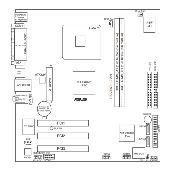
1.2.3 Motherboard layout 24.5cm (9.6in) CHA_FAN PS/2KBMS T: Mouse CPU_FAN B: Keyboard Super COM1 LGA775 USB1 USB2 ATX12V VIA P4M800 LAN_USB34 Top:Rear Speaker Out Center: Side Speaker Out ® Below: Center/Subwoofer CR2032 3V Lithium Cell CMOS Power BUZZER PCI1 RTL8100C SATA2 SB_PWR VIA VT837R... -
Page 13: Layout Contents
Internal audio connector (4-pin CD, AUX) 1-31 Digital audio connector (4-1 pin SPDIF_OUT) 1-31 System panel connector (10-1 pin PANEL) 1-34 System power LED (2-pin PLED) Hard disk drive activity LED (2-pin IDE_LED) Power button/soft-off button (2-pin PWRSW) Reset button (2-pin RESET) ASUS P5VDC-TVM... -
Page 14: Central Processing Unit (Cpu)
Contact your retailer immediately if the PnP cap is missing, or if you see any damage to the PnP cap/socket contacts/motherboard components. ASUS will shoulder the cost of repair only if the damage is shipment/transit-related. •... - Page 15 (B). Load plate Position the CPU on the socket, making sure that the gold triangle fixes on the bottom-left corner of the socket. The socket alignment keys should fit Alignment key into the CPU notches. Gold triangle mark ASUS P5VDC-TVM...
- Page 16 Close the load plate (A), then push the load lever (B) until it snaps into the retention tab. The CPU fits in only one correct orientation. DO NOT force the CPU into the socket to prevent benting the connectors on the socket and damaging the CPU.
-
Page 17: Installing The Cpu Heatsink And Fan
CPU fan connector. Motherboard hole Narrow end Fastener of the groove Make sure to orient each fastener with the narrow end of the groove pointing outward. (The photo shows the groove shaded for emphasis.) ASUS P5VDC-TVM... - Page 18 CPU FAN PWR CPU FAN IN CPU FAN PWM ® P5VDC-TVM CPU FAN Connector Do not forget to connect the CPU fan connector! Hardware monitoring errors can occur if you fail to plug this connector. 1-10 Chapter 1: Hardware information...
-
Page 19: Uninstalling The Cpu Heatsink And Fan
To uninstall the CPU heatsink and fan: Disconnect the CPU fan cable from the connector on the motherboard. Rotate each fastener counterclockwise. Pull up two fasteners at a time in a diagonal sequence to disengage the heatsink and fan assembly from the motherboard. ASUS P5VDC-TVM 1-11... - Page 20 Remove the heatsink and fan assembly from the motherboard. Rotate each fastener clockwise to reset the orientation. Narrow end of the groove When reset, each fastener should be oriented as shown, with the narrow groove directed outward. 1-12 Chapter 1: Hardware information...
-
Page 21: System Memory
The motherboard comes with two 240-pin Double Data Rate 2 (DDR2). The following figure illustrates the location of the sockets: ® P5VDC-TVM DDR2 DIMM Sockets 1.4.2 Memory Configurations You may install 256 MB, 512 MB and 1 GB unbuffered and non-ECC DDR2 DIMMs into the DIMM sockets using the memory configurations in this section. - Page 22 DDR2 (533 MHz) Qualified Vendors List Size Vendor Model Brand Side(s) Component DIMM supporpt 512MB Hynix HYMP564U64AP8-C3 Hynix HY5PS12821A • 512MB Hynix HYMP564U64AP8-Y4 AA Hynix HY5PS12821A • 256MB Infineon HYS64T32000HU-3.7-A HYB18T512160AF-3.7 • 256MB Infineon HYS64T32000HU-3.7-B HYB18T5121608BF-3.7 • 512MB Infineon HYS64000GU-3.7-A HYB18T512 •...
-
Page 23: Installing A Ddr2 Dimm
DIMM. Support the DIMM lightly with your fingers when pressing the retaining clips. The DIMM might get DDR2 DIMM notch damaged when it flips out with extra force. Remove the DIMM from the socket. ASUS P5VDC-TVM 1-15... -
Page 24: Expansion Slots
Expansion slots In the future, you may need to install expansion cards. The following sub-sections describe the slots and the expansion cards that they support. Make sure to unplug the power cord before adding or removing expansion cards. Failure to do so may cause you physical injury and damage motherboard components. -
Page 25: Interrupt Assignments
When using PCI cards on shared slots, ensure that the drivers support “Share IRQ” or that the cards do not need IRQ assignments; otherwise, conflicts will arise between the two PCI groups, making the system unstable and the card inoperable. ASUS P5VDC-TVM 1-17... -
Page 26: Pci Slots
1.5.4 PCI slots This motherboard has three PCI slots. The PCI slots support cards such as a LAN card, SCSI card, USB card, and other cards that comply with PCI specifications. The figure shows a LAN card installed on a PCI slot. 1-18 Chapter 1: Hardware information... -
Page 27: Jumpers
Except when clearing the RTC RAM, never remove the cap on CLRTC jumper default position. Removing the cap will cause system boot failure! CLRTC ® Normal Clear CMOS (Default) P5VDC-TVM Clear RTC RAM ASUS P5VDC-TVM 1-19... - Page 28 A warning message “Please make sure whether lockout jumper is set to correct or not.” appears when you flash the BIOS with the jumper cap. Remove the jumper cap before you update your BIOS. ® WRITE ENABLE WRITE PROTECT (Default) P5VDC-TVM BIOS_WP 1-20 Chapter 1: Hardware information...
-
Page 29: Connectors
In 4-channel, and 6-channel configuration, the function of this port becomes Front Speaker Out. Microphone port (pink). This port connects a microphone. Refer to the audio configuration table on the next page for the function of the audio ports with 6-channel configuration. ASUS P5VDC-TVM 1-21... -
Page 30: Internal Connectors
Pin 5 on the connector is removed to prevent incorrect cable connection when using a FDD cable with a covered Pin 5. FLOPPY NOTE: Orient the red markings on the floppy ribbon cable to PIN 1. ® PIN 1 P5VDC-TVM Floppy Disk Drive Connector 1-22 Chapter 1: Hardware information... - Page 31 IDE cable. • Use the 80-conductor IDE cable for Ultra DMA 133/100/66 IDE devices. ® PIN 1 NOTE: Orient the red markings (usually zigzag) on the ID ribbon cable to PIN 1. P5VDC-TVM IDE Connectors ASUS P5VDC-TVM 1-23...
-
Page 32: Serial Ata Connectors
RSATA_RXP1 RSATA_TXN1 RSATA_TXP1 SATA1 ® RSATA_RXN2 RSATA_RXP2 RSATA_TXN2 RSATA_TXP2 P5VDC-TVM SATA Connectors Important notes on Serial ATA • Install the Windows 2000 Service Pack 4 or the Windows ® ® Service Pack1 before using Serial ATA. • Plug your Serial ATA boot disk on the master port (SATA1 and SATA2) to support S3 function. -
Page 33: Cpu And Chassis Fan Connectors
Insufficient air flow inside the system may damage the motherboard components. These are not jumpers! Do not place jumper caps on the fan connectors! CHA_FAN ® CPU_FAN CPU FAN PWR CPU FAN IN CPU FAN PWM P5VDC-TVM FAN Connectors ASUS P5VDC-TVM 1-25... - Page 34 USB 2.0 specification that supports up to 480 Mbps connection speed. ® USB56 USB78 P5VDC-TVM USB 2.0 Connectors Never connect a 1394 cable to the USB connectors. Doing so will damage the motherboard! The USB module is purchased separately. 1-26...
- Page 35 PS_ON# +3.3VDC -12.0VDC +3.3VDC +3.3VDC P5VDC-TVM ATX Power Connectors • You can also use a Power Supply Unit (PSU) with a 24-pin ATX power connector on this motherboard. • Do not forget to connect the 4-pin ATX +12 V power plug;...
- Page 36 I/O module cable to this connector. ® FP_AUDIO P5VDC-TVM Front Panel Audio Connector Serial port connector (10-1 pin COM2) This connector is for a serial (COM) port. Connect the serial port module cable to this connector, then install the module to a slot opening at the back of the system chassis.
- Page 37 Ground (white) Left Audio Channel ® P5VDC-TVM Internal Audio Connectors 10. Digital audio connector (4-1 pin SPDIF_OUT) This connector is for additional Sony/Philips Digital Interface (S/PDIF) port(s). Connect the S/PDIF module cable to this connector, then install the module to a slot opening at the back of the system chassis.
-
Page 38: System Panel Connector
PWRSW F_PANEL ® IDE LED RESET P5VDC-TVM System Panel Connector • System power LED (2-pin PLED) This 2-pin connector is for the system power LED. Connect the chassis power LED cable to this connector. The system power LED lights up when you turn on the system power, and blinks when the system is in sleep mode. -
Page 39: Chapter 2: Bios Setup
This chapter tells how to change the system settings through the BIOS Setup menus. Detailed descriptions of the BIOS parameters are also provided. BIOS setup... -
Page 40: Bios Setup Program
BIOS setup program This motherboard supports a programmable firmware chip that you can update using the provided utility. Use the BIOS Setup program when you are installing a motherboard, reconfiguring your system, or prompted to “Run Setup.” This section explains how to configure your system using this utility. Even if you are not prompted to use the Setup program, you can change the configuration of your computer in the future. -
Page 41: Bios Menu Screen
Moves the cursor to the first field <-> or <PgDn> Moves the cursor to the last field <F5> Loads the previous values <F6> Loads the fail-safe defaults <F9> Loads the optimized defaults <F10> Saves changes and exits Setup ASUS P5VDC-TVM... -
Page 42: List Box
List box This box appears only in the opening screen. The box displays an initial list of configurable items in the menu you selected. Sub-menu Note that a right pointer symbol ( ) appears to the left of certain fields. This pointer indicates that you can display a sub-menu from this field. -
Page 43: Standard Bios Features
[Auto] To auto-detect the HDD’s Capacity 20021 MB size, head... on this channel Cylinder 38792 Head Precomp Landing Zone 38791 Sector : Move Enter:Select +/-/PU/PD:Value F10:Save&Exit ESC:Exit F1:General Help F5: Previous Values F6: Fail-Safe Defaults F9: Optimized Defaults ASUS P5VDC-TVM... - Page 44 IDE HDD Auto-Detection [Press Enter] Allows auto-detection of the hard disk drive’s specifications. IDE Channel 0, 1 Master/Slave [Auto] Sets the selected channel as Master or Slave. Configuration options: [None] [Auto] [Manual] Access Mode [Auto] This item allows the user to select the sector addressing mode. CHS mode supports 528 MB hard disks.
- Page 45 Incorrect settings may cause the system to fail to recognize the installed hard disk. Capacity Displays the auto-detected hard disk capacity. This item is not configurable. Cylinder Shows the number of the hard disk cylinders. This item is not configurable. ASUS P5VDC-TVM...
- Page 46 Head Shows the number of the hard disk read/write heads. This item is not configurable. Precomp Shows the number of precomp per track. This item is not configurable. Landing Zone Shows the number of landing zone per track. This item is not configurable.
-
Page 47: Advanced Bios Features
Configuration options: [Disabled] [Enabled] Hard Disk Boot Priority [Press Enter] Allows you to select the hard disk boot device priority. The number of devices that appears on the screen depends on the number of devices installed in the system. ASUS P5VDC-TVM... - Page 48 First/Second/Third/Fourth Boot Device Allows you to assign the boot device priority. Configuration options: [Floppy] [LS120] [Hard Disk] [CDROM] [ZIP] [USB-FDD] [USB-ZIP] [USB-CDROM] [LAN] [Disabled] Boot Up Floppy Seek [Disabled] When [Enabled], the BIOS will seek the flopy disk drive to determine whether the drive has 40 or 80 tracks.
-
Page 49: Integrated Peripherals
IDE Primary Slave UDMA [Auto] IDE Secondary Master UDMA [Auto] IDE Secondary Slave UDMA [Auto] On-Chip Serial ATA [Enabled] SATA Mode [IDE] : Move Enter:Select +/-/PU/PD:Value F10:Save&Exit ESC:Exit F1:General Help F5: Previous Values F6: Fail-Safe Defaults F9: Optimized Defaults ASUS P5VDC-TVM 2-11... - Page 50 IDE Primary, Secondary Master/Slave PIO [Auto] This option lets you set a PIO (Programmed Input/Output) mode for the IDE device. Modes 0 through 4 provide successive increase in performance. Configuration options: [Auto] [Mode 0] [Mode 1] [Mode 2] [Mode 3] [Mode 4] IDE Primary, Secondary Master/Slave UDMA [Auto] Ultra DMA capability allows improved transfer speeds and data integrity for compatible IDE devices.
-
Page 51: Onboard Device
Allows you to enable or disable the onboard LAN device support. Configuration options: [Disabled] [Enabled] Onboard LAN Boot ROM [Disabled] Allows you to enable or disable the boot ROM of the onboard LAN chip. Configuration options: [Enabled] [Disabled] ASUS P5VDC-TVM 2-13... -
Page 52: Superio Device
SuperIO Device This sub-menu allows you to set the configurations for SuperIO devices. Select an item then press <Enter> to edit. Phoenix - Award BIOS CMOS Setup Utility SuperIO Device Select Menu Onboard Serial Port 1 [3F8/IRQ4] Onboard Serial POrt 2 [2F8/IRQ3] Item Specific Help Onboard Parallel Port... -
Page 53: Power Management Setup
4 seconds to power off the system. Configuration options: [Instant-Off] [Delay 4 Sec] Resume by PCI PME [Enabled] Enables or disables system wake-up by power management event (PME). Configuration options: [Disabled] [Enabled] ASUS P5VDC-TVM 2-15... - Page 54 Resume by Ring [Enabled] Allows you to enable or disable system power up when the external modem receives a call while the computer is in soft-off mode. Configuration options: [Disabled] [Enabled] The computer cannot receive or transmit data until the computer and applications are fully running.
-
Page 55: Pc Health Status
VCORE Voltage, 3.3V Voltage, +5V in, +12V in The onboard hardware monitor automatically detects the voltage output through the onboard voltage regulators. CPU Fan Speed Control [Enabled] Allows you to enable or disable the CPU fan speed controller. Configuration options: [Enabled] [Disabled] ASUS P5VDC-TVM 2-17... -
Page 56: Other Items
Start Up Temperature (ºC) [50] Allows you to set the fan start-up temperature. Configuration options: [0] [1] ~ [100] Full Speed Temperature (ºC) [70] Allows you to set the threshold temperature before the fan begins running at full speed. Configuration options: [0] [1] ~ [100] Start Up PWM [60] Sets the start-up Pulse Width Modulation (PWM) value when the fan starts running.