Asus P5VD2 VM - SE Motherboard - Micro ATX User Manual
P5vd2-vm english edition user's manual
Hide thumbs
Also See for P5VD2 VM - SE Motherboard - Micro ATX:
- Mode d'emploi (110 pages) ,
- User manual (100 pages)
Table of Contents
Advertisement
Advertisement
Table of Contents

Related Manuals for Asus P5VD2 VM - SE Motherboard - Micro ATX


Summary of Contents for Asus P5VD2 VM - SE Motherboard - Micro ATX
- Page 1 P5VD2-VM/ P5V-VM SE DH...
- Page 2 Product warranty or service will not be extended if: (1) the product is repaired, modified or altered, unless such repair, modification of alteration is authorized in writing by ASUS; or (2) the serial number of the product is defaced or missing.
-
Page 3: Table Of Contents
Special features ................1-2 1.3.1 Product highlights ............1-2 1.3.2 Innovative ASUS features ..........1-4 1.3.3 ASUS Digital Home for P5V-VM SE DH special features ................1-5 Before you proceed ..............1-7 Motherboard overview ..............1-8 1.5.1 Placement direction ............1-8 1.5.2... - Page 4 2.1.1 ASUS Update utility ............2-2 2.1.2 Creating a bootable floppy disk ........2-5 2.1.3 ASUS EZ Flash 2 utility ........... 2-6 2.1.4 Updating the BIOS ............2-7 2.1.5 ASUS CrashFree BIOS 2 utility ........2-9 BIOS setup program ..............2-11 2.2.1...
- Page 5 Boot Settings Configuration ......... 2-34 2.6.4 2.6.5 Security ................. 2-36 Tools menu ................. 2-38 2.7.1 ASUS EZ Flash 2 ............2-38 Exit menu ..................2-39 Chapter 3: Software support Installing an operating system ........... 3-2 Support CD information .............. 3-2 3.2.1 Running the support CD ..........
-
Page 6: Notices
Notices Federal Communications Commission Statement This device complies with Part 15 of the FCC Rules. Operation is subject to the following two conditions: • This device may not cause harmful interference, and • This device must accept any interference received including interference that may cause undesired operation. -
Page 7: Safety Information
Safety information Electrical safety • To prevent electrical shock hazard, disconnect the power cable from the electrical outlet before relocating the system. • When adding or removing devices to or from the system, ensure that the power cables for the devices are unplugged before the signal cables are connected. -
Page 8: About This Guide
Refer to the following sources for additional information and for product and software updates. ASUS websites The ASUS website provides updated information on ASUS hardware and software products. Refer to the ASUS contact information. Optional documentation Your product package may include optional documentation, such as warranty flyers, that may have been added by your dealer. -
Page 9: Conventions Used In This Guide
Conventions used in this guide To make sure that you perform certain tasks properly, take note of the following symbols used throughout this manual. DANGER/WARNING: Information to prevent injury to yourself when trying to complete a task. CAUTION: Information to prevent damage to the components when trying to complete a task. - Page 10 High definition audio, ADI AD1986A SoundMax ® 5.1-channel CODEC Supports Jack-sensing function Realtek RTL8110SC Gigabit LAN Controller ® Supports up to 8 USB 2.0 ports Special features ASUS Q-Fan ASUS EZ Flash 2 ASUS CrashFree BIOS 2 MyLogo™ (continued on the next page)
- Page 11 P5VD2-VM/P5V-VM SE DH specifications summary Overclocking Features ASUS C.P.R. (CPU Parameter Recall) SFS (Stepless Frequency Selection) from 133MHz up to 300MHz at 1MHz increment Fixed PCI-E/SATA frequencies. Rear panel 1 x Parallel port 1 x External SATA 1 x LAN (RJ-45) port 4 x USB 2.0/1.1 ports (P5VD2-VM)
- Page 12 Accessories ASUS DH Remote Receiver ASUS WiFi-AP Solo omni-directional antenna ASUS MP3-In Module Wirelss LAN Up to 54Mbps IEEE 802.11b/g (ASUS WiFi-AP Solo) Rear Panel 1 x WiFi-AP Solo antenna jack Internal Connectors 1 x MP3-In connector Support CD contents ASUS WiFi-AP Solo, ASUS DH Remote™...
-
Page 13: Chapter 1: Product Introduction
This chapter describes the motherboard features and the new technologies it supports. Product introduction ASUS P5VD2-VM/P5V-VM SE DH... -
Page 14: Welcome
® The motherboard delivers a host of new features and latest technologies, making it another standout in the long line of ASUS quality motherboards! Before you start installing the motherboard, and hardware devices on it, check the items in your package with the list below. - Page 15 See pages 1-28 and 1-31 for details. Dual RAID solution The onboard VIA VT8237A chipset allows RAID 0, RAID 1, and JBOD configuration for two SATA connectors, and JMicron JMB363 SATA controller also supports RAID 0, RAID 1, and JBOD. ASUS P5VD2-VM/P5V-VM SE DH...
-
Page 16: Innovative Asus Features
Internet, LAN, and file sharing requirements. 1.3.2 Innovative ASUS features CrashFree BIOS 2 This feature allows you to restore the original BIOS data from the support CD in case when the BIOS codes and data are corrupted. This protection eliminates the need to buy a replacement ROM chip. -
Page 17: Asus Digital Home For P5V-Vm Se Dh Special Features
ASUS WiFi-AP Solo (Only for P5V-VM SE DH) The ASUS WiFi-AP Solo allows a new level of versitility for your PC, enabling it to create a complete wireless home network in either AP or wirelesss client mode. Users will be able to play LAN games, connecting to the Internet, access and share printers, and use Skype from anywhere within range. - Page 18 ASUS DH Remote™ (Only for P5V-VM SE DH) The ASUS DH Remote™ is a convenient PC remote controller that gives users unprecedented control over their PCs from the comfort of their couches. With the touch of a button, users can instantly operate the following functions: Power: Turns the computer on/off.
-
Page 19: Before You Proceed
The illustration below shows the location of the onboard LED. SB_PWR ® Standby Powered Onboard LED Power ASUS P5VD2-VM/P5V-VM SE DH... -
Page 20: Motherboard Overview
Motherboard overview Before you install the motherboard, study the configuration of your chassis to ensure that the motherboard fits into it. Make sure to unplug the power cord before installing or removing the motherboard. Failure to do so can cause you physical injury and damage motherboard components. -
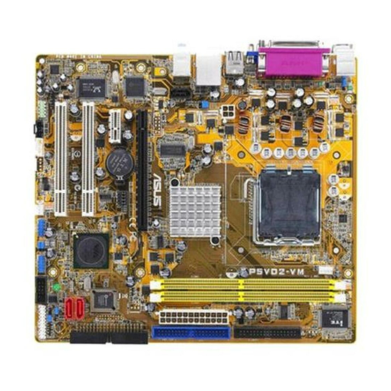
Page 21: Motherboard Layout
1.5.3 P5VD2-VM/P5V-VM SE DH Motherboard layout • The WIFI connecotr and MP3IN connector are only for P5V-VM SE DH. • USB1 and USB2 ports are only for P5VD2-VM. ASUS P5VD2-VM/P5V-VM SE DH... -
Page 22: Central Processing Unit (Cpu)
Contact your retailer immediately if the PnP cap is missing, or if you see any damage to the PnP cap/socket pins/motherboard components. ASUS will shoulder the cost of repair only if the damage is shipment/transit-related. - Page 23 Position the CPU over the socket, making sure that the gold triangle is on the bottom-left corner of the socket. The socket alignment key should fit into Alignment key the CPU notch. Gold triangle mark ASUS P5VD2-VM/P5V-VM SE DH 1-11...
- Page 24 Close the load plate (A), then push the load lever (B) until it snaps into the retention tab. The CPU fits in only one correct orientation. DO NOT force the CPU into the socket to prevent bending the connectors on the socket and damaging the CPU! Notes on Intel Hyper-Threading Technology ®...
-
Page 25: Installling The Cpu Heatsink And Fan
Place the heatsink on top of the installed CPU, making sure that the four fasteners match the holes on the motherboard. Fastener Motherboard hole Make sure each fastener is oriented as shown, with the narrow groove directed outward. ASUS P5VD2-VM/P5V-VM SE DH 1-13... - Page 26 Push down two fasteners at a time in a diagonal sequence to secure the heatsink and fan assembly in place. When the fan and heatsink assembly is in place, connect the CPU fan cable to the connector on the motherboard labeled CPU_FAN. CPU_FAN CPU FAN PWR CPU FAN IN...
-
Page 27: Uninstalling The Cpu Heatsink And Fan
Disconnect the CPU fan cable from the connector on the motherboard labeled CPU_ FAN. Rotate each fastener counterclockwise. Pull up two fasteners at a time in a diagonal sequence to disengage the heatsink and fan assembly from the motherboard. ASUS P5VD2-VM/P5V-VM SE DH 1-15... - Page 28 Remove the heatsink and fan assembly from the motherboard. Rotate each fastener clockwise to reset the orientation. Narrow end of the groove The narrow end of the groove should point outward after resetting. (The photo shows the groove shaded for emphasis.) 1-16 Chapter 1: Product introduction...
-
Page 29: System Memory
Refer to the DDR2 Qualified Vendors List on the next page for details. • Due to chipset resource allocation, the system may detect less than 4 GB system memory when you installed two 2 GB DDR2 memory modules. ASUS P5VD2-VM/P5V-VM SE DH 1-17... - Page 30 Qualified Vendors Lists (QVL) DDR2-667 MHz capability DIMM support Size Vendor Model Brand Side(s) Component 512MB KINGSTON E5108AE-6E-E KVR667D2N5/512 1024MB KINGSTON E5108AE-6E-E KVR667D2N5/1G 512MB KINGSTON E5108AE-6E-E KVR667D2E5/512 256MB KINGSTON HYB18T256800AF3 KVR667D2N5/256 256MB Qimonda HYB18T512160AF-3S HYS64T32000HU-3S-A 512MB Qimonda HYB18T512800AF3S HYS64T64000HU-3S-A 1024MB Qimonda HYB18T512800AF3S HYS64T128020HU-3S-A...
- Page 31 Side(s): SS - Single-sided DS - Double-sided DIMM support: Supports one module inserted in any slot as Single-channel memory configuration Supports one pair of modules inserted into yellow slots as one pair of Single-channel memory configuration ASUS P5VD2-VM/P5V-VM SE DH 1-19...
-
Page 32: Installing A Dimm
1.7.3 Installing a DIMM Make sure to unplug the power supply before adding or removing DIMMs or other system components. Failure to do so may cause severe damage to both the motherboard and the components. Unlock a DIMM socket by pressing DDR2 DIMM notch the retaining clips outward. -
Page 33: Expansion Slots
Turn on the system and change the necessary BIOS settings, if any. See Chapter 2 for information on BIOS setup. Assign an IRQ to the card. Refer to the tables on the next page. Install the software drivers for the expansion card. ASUS P5VD2-MX/P5V-VM DH 1-21... -
Page 34: Interrupt Assignments
1.8.3 Interrupt assignments Standard interrupt assignments Priority Standard Function System Timer Keyboard Controller • Re-direct to IRQ#9 Communications Port (COM)* IRQ holder for PCI steering* Floppy Disk Controller Printer Port (LPT1)* System CMOS/Real Time Clock IRQ holder for PCI steering* IRQ holder for PCI steering* PCI-E x1 PS/2 Compatible Mouse Port*... -
Page 35: Pci Slots
See page 1-26 “4. PCI Express x 1 and External SATA jumper setting” for details. 1.8.6 PCI Express x16 slot This motherboard supports PCI Express x16 graphic cards that comply with PCI Express specifications. The figure shows a graphics card installed on the PCI Express x16 slot. ASUS P5VD2-MX/P5V-VM DH 1-23... -
Page 36: Jumpers
Jumpers Clear RTC RAM (CLRTC) This jumper allows you to clear the Real Time Clock (RTC) RAM in CMOS. You can clear the CMOS memory of date, time, and system setup parameters by erasing the CMOS RTC RAM data. The onboard button cell battery powers the RAM data in CMOS, which include system setup information such as system passwords. - Page 37 The USBPWR12 and USBPWR34 jumpers are for the rear USB ports. The USBPWR56 and USBPWR78 jumper is for the internal USB connectors that you can connect to additional USB ports. USBPW34 USBPW12 +5VSB (Default) USBPW56 ® USBPW78 +5VSB USB device wake-up (Default) ASUS P5VD2-MX/P5V-VM DH 1-25...
- Page 38 • USB1 and USB2 ports are only for P5VD2-VM. • For P5V-VM SE DH, USBPW12 jumper controls Wifi-AP Solo. Do not change the setting. • The USB device wake-up feature requires a power supply that can provide 500mA on the +5VSB lead for each USB port; otherwise, the system would not power up.
-
Page 39: 1.10 Connectors
Refer to the audio configuration table for the function of the audio ports in 2, 4, or 6-channel configuration. Audio 2, 4, or 6-channel configuration Port Headset 4-channel 6-channel 2-channel Light Blue Line In Surround Surround Lime Headphone/Front Front Front Pink Microphone Microphone Center/Subwoofer ASUS P5VD2-MX/P5V-VM DH 1-27... - Page 40 Connect the moveable omni-directional antenna to this jack. WIFI-AP Solo LED indicator (Only for P5V-VM SE DH). The WIFI-AP Solo comes with a green data transmission LED (AIR). Refer to the ASUS WiFi-AP Solo user guide. USB 2.0 ports 1 and 2. These two 4-pin Universal Serial Bus (USB) ports are available for connecting USB 2.0 devices.
-
Page 41: Internal Connectors
Pin 5 on the connector is removed to prevent incorrect cable connection when using an FDD cable with a covered Pin 5. FLOPPY ® PIN 1 NOTE: Orient the red markings on the floppy ribbon cable to PIN 1. Floppy disk drive connector ASUS P5VD2-MX/P5V-VM DH 1-29... -
Page 42: Ide Connectors
Primary/Secondary IDE connectors (40-1 pin PRI_IDE [blue]; 40-1 pin SEC_IDE [black]) The onboard IDE connectors are for Ultra DMA 133/100/66 signal cables. There are three connectors on each Ultra DMA 133/100/66 signal cable: blue, black, and gray. Connect the blue connector to the motherboard’s IDE connector, then select one of the following modes to configure your device(s). - Page 43 ATA hard disk drive, to configure for RAID via the onboard Serial ATA RAID controller. SATA_RAID1 ® RSATA_TXP2 RSATA_TXN2 RSATA_RXP2 RSATA_RXN2 SATA RAID connector Do not remove/unplug external SATA devices when running under RAID mode. ASUS P5VD2-VM/P5V-VM SE DH 1-31...
-
Page 44: Fan Connectors
CPU and Chassis fan connectors (4-pin CPU_FAN, 3-pin CHA_FAN) The fan connectors support cooling fans of 350mA~740mA (8.88W max.) or a total of 1A~2.22A (26.64W max.) at +12V. Connect the fan cables to the fan connectors on the motherboard, making sure that the black wire of each cable matches the ground pin of the connector. - Page 45 This connector is for a serial (COM) port. Connect the serial port module cable to this connector, then install the module to a slot opening at the back of the system chassis. COM2 PIN 1 ® COM port connector The Serial (COM) port module is purchased separately. ASUS P5VD2-VM/P5V-VM SE DH 1-33...
- Page 46 Internal audio connectors (4-pin CD, AUX) These connectors allow you to receive stereo audio input from sound sources such as a CD-ROM, TV tuner, MPEG card or modem. (Black) (White) ® Internal audio connectors 10. USB connectors (10-1 pin USB56, USB78) These connectors are for USB 2.0 ports.
-
Page 47: Chassis Intrusion Connector
By default, the pins labeled “Chassis Signal” and “Ground” are shorted with a jumper cap. Remove the jumper caps only when you intend to use the chassis intrusion detection feature. CHASSIS ® (Default) Chassis intrusion connector ASUS P5VD2-VM/P5V-VM SE DH 1-35... - Page 48 13. MP3-In connector (4-pin MP3IN [red]) (Only for P5V-VM SE DH) This connector is for the MP3-In module that allows you to connect your MP3 player to the speakers of the computer. For more information, refer to the MP3-In™ quick installation guide for details. MP3IN ®...
-
Page 49: System Panel Connector
BIOS settings. Pressing the power switch for more than four seconds while the system is ON turns the system OFF. • Reset button (2-pin RESET) This 2-pin connector is for the chassis-mounted reset button for system reboot without turning off the system power. ASUS P5VD2-VM/P5V-VM SE DH 1-37... - Page 50 1-38 Chapter 1: Product introduction...
-
Page 51: Chapter 2: Bios Setup
This chapter tells how to change the system settings through the BIOS Setup menus. Detailed descriptions of the BIOS parameters are also provided. BIOS setup ASUS P5VD2-VM/P5V-VM SE DH... -
Page 52: Managing And Updating Your Bios
BIOS using the ASUS Update or Award BIOS Flash utilities. 2.1.1 ASUS Update utility The ASUS Update is a utility that allows you to manage, save, and update the motherboard BIOS in Windows environment. The ASUS Update utility allows you ®... - Page 53 To update the BIOS through the Internet: Launch the ASUS Update utility from the Windows desktop by clicking Start ® > Programs > ASUS > ASUSUpdate > ASUSUpdate. The ASUS Update main window appears. Select Update BIOS from the Select the ASUS FTP site nearest...
- Page 54 To update the BIOS through a BIOS file: Launch the ASUS Update utility from the Windows desktop by clicking Start ® > Programs > ASUS > ASUSUpdate > ASUSUpdate. The ASUS Update main window appears. Select Update BIOS from a file option from the drop-down menu, then click Next.
-
Page 55: Creating A Bootable Floppy Disk
From the Open field, type D:\bootdisk\makeboot a: assuming that D: is your optical drive. e. Press <Enter>, then follow screen instructions to continue. Copy the original or the latest motherboard BIOS file to the bootable floppy disk. ASUS P5VD2-VM/P5V-VM SE DH... -
Page 56: Asus Ez Flash 2 Utility
2.1.3 ASUS EZ Flash 2 utility The ASUS EZ Flash 2 feature allows you to update the BIOS without having to go through the long process of booting from a floppy disk and using a DOS-based utility. The EZ Flash utility is built-in the BIOS chip so it is accessible by pressing <Alt>... -
Page 57: Updating The Bios
The Basic Input/Output System (BIOS) can be updated using the AwardBIOS Flash Utility. Follow these instructions to update the BIOS using this utility. Download the latest BIOS file from the ASUS web site. Rename the file to P5VD2VM.BIN/P5VVMSEDH.BIN and save it to a floppy disk. - Page 58 Press <N> when the utility prompts you to save the current BIOS file. The following screen appears. The utility verifies the BIOS AwardBIOS Flash Utility for ASUS V1.14 file in the floppy disk and (C) Phoenix Technologies Ltd. All Rights Reserved starts flashing the BIOS file.
-
Page 59: Asus Crashfree Bios 2 Utility
2.1.5 ASUS CrashFree BIOS 2 utility The ASUS CrashFree BIOS 2 is an auto recovery tool that allows you to restore the BIOS file when it fails or gets corrupted during the updating process. You can update a corrupted BIOS file using the motherboard support CD or the floppy disk that contains the updated BIOS file. -
Page 60: Recovering The Bios From The Support Cd
Restart the system after the utility completes the updating process. The recovered BIOS may not be the latest BIOS version for this motherboard. Visit the ASUS website (www.asus.com) to download the latest BIOS file. 2-10 Chapter 2: BIOS setup... -
Page 61: Bios Setup Program
The BIOS setup screens shown in this section are for reference purposes only, and may not exactly match what you see on your screen. • Visit the ASUS website (www.asus.com) to download the latest BIOS file for this motherboard and . ASUS P5VD2-VM/P5V-VM SE DH... -
Page 62: Bios Menu Screen
The BIOS setup screens shown in this chapter are for reference purposes only, and may not exactly match what you see on your screen. • Visit the ASUS website (www.asus.com) to download the latest BIOS information. 2-12 Chapter 2: BIOS setup... -
Page 63: Legend Bar
A configurable field is enclosed in brackets, and is highlighted when selected. To change the value of a field, select it then press <Enter> to display a list of options. Refer to “2.2.7 Pop-up window.” ASUS P5VD2-VM/P5V-VM SE DH 2-13... -
Page 64: Pop-Up Window
Legacy Diskette A: physical size of diskette drive A. Primary IDE Master [ST321122A] Disabled ..[ ] Primary IDE Slave [ASUS CDS520/A] 720K , 3.5 in..[ ] Secondary IDE Master [None] 1.44M, 3.5 in..[ ] Secondary IDE Slave... -
Page 65: Main Menu
System Date [Day xx/xx/xxxx] Allows you to set the system date. 2.3.3 Legacy Diskette A [1.44M, 3.5 in.] Sets the type of floppy drive installed. Configuration options: [Disabled] [720K , 3.5 in.] [1.44M, 3.5 in.] ASUS P5VD2-VM/P5V-VM SE DH 2-15... -
Page 66: Primary And Secondary Ide Master/Slave
2.3.4 Primary and Secondary IDE Master/Slave While entering Setup, the BIOS automatically detects the presence of IDE devices. There is a separate sub-menu for each IDE device. Select a device item then press <Enter> to display the IDE device information. Phoenix-Award BIOS CMOS Setup Utility Main Select Menu... - Page 67 FDISK, to partition and format new IDE hard disk drives. This is necessary so that you can write or read data from the hard disk. Make sure to set the partition of the Primary IDE hard disk drives to active. ASUS P5VD2-VM/P5V-VM SE DH 2-17...
-
Page 68: Sata 1/2
2.3.5 SATA 1/2 While entering Setup, the BIOS automatically detects the presence of Serial ATA devices. There is a separate sub-menu for each SATA device. Select a device item then press <Enter> to display the SATA device information. Phoenix-Award BIOS CMOS Setup Utility Main Select Menu SATA 1... -
Page 69: Hdd Smart Monitoring
Allows you to enable or disable the HDD Self-Monitoring Analysis and Reporting Technology (SMART) feature. Configuration options: [Disabled] [Enabled] 2.3.7 Installed Memory [xxx MB] Shows the size of installed memory. 2.3.8 Usable Memory [XXX MB] Shows the size of usable memory. ASUS P5VD2-VM/P5V-VM SE DH 2-19... -
Page 70: Advanced Menu
Advanced menu The Advanced menu items allow you to change the settings for the CPU and other system devices. Take caution when changing the settings of the Advanced menu items. Incorrect field values can cause the system to malfunction. Phoenix-Award BIOS CMOS Setup Utility Main Advanced Power... -
Page 71: Chipset
[Manual]. CAS Latency Time [4] Configuration options: [2] [3] [4] [5] Bank Interleave [4 Bank] Configuration options: [Disabled] [2 Bank] [4 Bank] [8 Bank] Precharge to Active(Trp) [3T] Configuration options: [2T] [3T] [4T] [5T] ASUS P5VD2-VM/P5V-VM SE DH 2-21... - Page 72 Active to Precharge(Tras) [15T] Configuration options: [05T] [06T]...[20T] Active to CMD(Trcd) [3T] Configuration options: [2T] [3T] [4T] [5T] REF to ACT/REF(Trfc) [34T/35T] Configuration options: [07T/08T] [08T/09T] [09/10T]...[70T/71T] Act(o) to ACT(1) (TRRD) [3T] Configuration options: [2T] [3T] Frequency/Voltage control Phoenix-Award BIOS CMOS Setup Utility Advanced Select Menu Frequency/Voltage control...
-
Page 73: Pcipnp
Configuration options: [Auto] [Manual] When the item Resources Controlled By is set to [Auto], the item IRQ Resources is grayed out and not user-configurable. Refer to the section “IRQ Resources” for information on how to enable this item. ASUS P5VD2-VM/P5V-VM SE DH 2-23... -
Page 74: Irq Resources
IRQ Resources This sub-menu is activated only when the Resources Controlled By item is set to Manual. Phoenix-Award BIOS CMOS Setup Utility Advanced Select Menu IRQ Resources IRQ-3 assigned to [PCI Device] Item Specific Help IRQ-4 assigned to [PCI Device] IRQ-5 assigned to [PCI Device] Legacy ISA for devices... -
Page 75: Onboard Devices Configuration
Configuration options: [Auto] [Disabled] Onboard LAN [Enabled] Enables or disables the onboard LAN controller. Configuration options: [Enabled] [Disabled] Onboard LAN Boot ROM [Disabled] Enables or disables the onboard LAN boot ROM. Configuration options: [Enabled] [Disabled] ASUS P5VD2-VM/P5V-VM SE DH 2-25... - Page 76 Serial Port1 Address [3F8/IRQ4] Allows you to select the Serial Port1 base address. Configuration options: [Disabled] [3F8/IRQ4] [2F8/IRQ3] [3E8/IRQ4] [2E8/IRQ3] [Auto] Parallel Port Address [378/IRQ7] Allows you to select the Parallel Port address. Configuration options: [Disabled] [378/IRQ7] [278/IRQ5] [3BC/IRQ7] Parallel Port Mode [Bi-Directional] Allows you to select the Parallel Port mode.
-
Page 77: Usb Configuration
Allows you to enable or disable the USB 2.0 controller. Configuration options: [Disabled] [Enabled] USB Legacy Support [Auto] Allows you to enable or disable support for USB devices on legacy operating systems (OS). Configuration options: [Auto] [Enabled] [Disabled] ASUS P5VD2-VM/P5V-VM SE DH 2-27... -
Page 78: Power Menu
Power menu The Power menu items allow you to change the settings for the Advanced Configuration and Power Interface (ACPI) and the Advanced Power Management (APM). Select an item then press <Enter> to display the configuration options. Phoenix-Award BIOS CMOS Setup Utility Main Advanced Power... - Page 79 To set the date of alarm, highlight this item and press <Enter> to display the Date of Month Alarm pop-up menu. Key-in a value within the specified range then press <Enter>. Configuration options: [Min=0] [Max=31 ASUS P5VD2-VM/P5V-VM SE DH 2-29...
- Page 80 Alarm Time (hh:mm) To set the time of alarm: Highlight this item and press <Enter> to display a pop-up menu for the hour field. Key-in a value (Min=0, Max=23), then press <Enter>. Press <TAB> to move to the minutes field then press <Enter>. Key-in a minute value (Min=0, Max=59), then press <Enter>.
-
Page 81: Hardware Monitor
Chassis, and chip fan speeds in rotations per minute (RPM). If any of the fans is not connected to the motherboard, the field shows 0. These items are not user- configurable. CPU Fan Speed warning [600 RPM] Sets the CPU fan speed warning feature. Configuration options: [Disabled] [600RPM] [1200RPM] [1600RPM] ASUS P5VD2-VM/P5V-VM SE DH 2-31... - Page 82 Start Up Temperature(ºC) [50] Fan will start up when the temperature is over the set value. Configuration options: [Min=0] [Max=100] Full Speed Temperature(ºC) [70] Fan will run at full speed when the temperature is over the set value. Configuration options: [Min=0] [Max=100] Start Up PWM [80] Sets the PWM value when the fan starts up.
-
Page 83: Boot Menu
Configuration options: [Removable] [Hard Disk] [CDROM] [Disabled] 2.6.2 Removable Drives Phoenix-Award BIOS CMOS Setup Utility Boot Removable Drives Select Menu Item Specific Help 1. Floppy Disks 1. Floppy Disks Allows you to assign a removable drive attached to the system. ASUS P5VD2-VM/P5V-VM SE DH 2-33... -
Page 84: Hard Disk Drives
2.6.3 Hard Disk Drives Phoenix-Award BIOS CMOS Setup Utility Boot Hard Disk Drives Select Menu Item Specific Help 1. Bootable Add-in Cards 1. Bootable Add-in Cards Allows you to assign bootable add-in cards attached to the system. 2.6.4 Boot Settings Configuration Phoenix-Award BIOS CMOS Setup Utility Boot Boot Settings Configuration... - Page 85 Allows you to enable or disable the full screen logo display feature. Configuration options: [Disabled] [Enabled] Make sure that the above item is set to [Enabled] if you want to use the ASUS MyLogo™ feature. Halt On [All, But Keyboard] Allows you to error report type.
-
Page 86: Security
2.6.5 Security Phoenix-Award BIOS CMOS Setup Utility Boot Select Menu Boot Settings Configuration Supervisor Password Clear Item Specific Help User Password Clear Password Check [Setup] Supervisor Password User Password These fields allow you to set passwords: To set a password: Select an item then press <Enter>. -
Page 87: Password Check
This field requires you to enter the password before entering the BIOS setup or the system. Select [Setup] to require the password before entering the BIOS Setup. Select [System] to require the password before entering the system. Configuration options: [Setup] [System] ASUS P5VD2-VM/P5V-VM SE DH 2-37... -
Page 88: Tools Menu
F10: Save and Exit 2.7.1 ASUS EZ Flash 2 Allows you to run ASUS EZ Flash 2. When you press <Enter>, a confirmation message appears. Use the left/right arrow key to select between [Yes] or [No], then press <Enter> to confirm your choice. -
Page 89: Exit Menu
Select this option only if you do not want to save the changes that you made to the Setup program. If you made changes to fields other than System Date, System Time, and Password, the BIOS asks for a confirmation before exiting. ASUS P5VD2-VM/P5V-VM SE DH 2-39... -
Page 90: Load Setup Defaults
Load Setup Defaults This option allows you to load the default values for each of the parameters on the Setup menus. When you select this option or if you press <F5>, a confirmation window appears. Select YES to load default values. Select Exit & Save Changes or make other changes before saving the values to the non-volatile RAM. -
Page 91: Chapter 3: Software Support
This chapter describes the contents of the support CD that comes with the motherboard package. Software support ASUS P5VD2-VM/P5V-VM SE DH... -
Page 92: Installing An Operating System
The contents of the support CD are subject to change at any time without notice. Visit the ASUS website(www.asus.com) for updates. 3.2.1 Running the support CD Place the support CD to the optical drive. The CD automatically displays the Drivers menu if Autorun is enabled in your computer. -
Page 93: Drivers Menu
® USB 2.0 Driver Installs the USB 2.0 driver. ASUS WiFi-AP Solo (For P5V-VM SE DH only) Installs the ASUS WiFi-AP Solo™ driver and application. ASUS DH Remote (For P5V-VM SE DH only) Installs the ASUS DH Remote driver and application. -
Page 94: Utilities Menu
This utility helps you keep your computer in healthy operating condition. ASUS Update The ASUS Update utility allows you to update the motherboard BIOS in a Windows environment. This utility requires an Internet connection either through a ®... -
Page 95: Make Disk Menu
The Manuals menu contains a list of supplementary user manuals. Click an item to open the folder of the user manual. Most user manual files are in Portable Document Format (PDF). Install the Adobe Acrobat Reader from the Utilities menu before opening a user manual ® ® file. ASUS P5VD2-VM/P5V-VM SE DH... -
Page 96: Asus Contact Information
Allows you to open the JMicron RAID BIOS user’s manual. 3.2.6 ASUS Contact information Click the Contact tab to display the ASUS contact information. You can also find this information on the inside front cover of this user guide. Chapter 3: Software support... -
Page 97: Raid Configurations
Spanning does not deliver any advantage over using separate disks independently and does not provide fault tolerance or other RAID performance benefits. ASUS P5VD2-VM/P5V-VM SE DH... -
Page 98: Installing Hard Disks
If you want to boot the system from a hard disk drive included in a RAID set, copy first the RAID driver from the support CD to a floppy disk before you install an operating system to a selected hard disk drive. Refer to section “3.4 Creating a RAID driver disk”... -
Page 99: Create Array
If you want to auto-configure, proceed to the next step, otherwise, skip to step 5. Select Auto Setup for Performance and press <Enter>. The following confirmation message appears. Auto create array will destroy all data on disks, Continue? (Y/N) ASUS P5VD2-VM/P5V-VM SE DH... -
Page 100: Raid 1 For Data Protection
Press <Y> to confirm or <N> to return to the configuration options. If you selected <Y>, proceed to step 9. Select Select Disk Drives, then press <Enter>. Use arrow keys to select disk drive, then press <Enter> to mark selected drive. An asterisk appears before a selected drive. - Page 101 If you select <N>, the following confirmation message appears. The data on the selected disks will 10. Press <Y> to confirm or <N> to return to the configuration options. 11. Press <Esc> to go back to main menu. ASUS P5VD2-VM/P5V-VM SE DH 3-11...
-
Page 102: Jmicron
3.3.2 JMicron RAID Configuration ® The JMicron Serial ATA controller allows you to configure RAID 0 and RAID 1 sets ® on the external Serial ATA hard disk drives. Before creating a RAID set Prepare the following items: Two HDDs, preferably with the same model and capacity. A write-enabled floppy disk Microsoft Windows... -
Page 103: Creating A Raid Set
In the main JMB363 RAID BIOS menu, highlight Create RAID Disk Drive using the up/down arrow key then press <Enter>. [Main Menu] Create RAID Disk Drive Delete RAID Disk Drive Revert HDD to Non-RAID Repair Mirror Conflict Save and Exit Setup Exit Without Saving ASUS P5VD2-VM/P5V-VM SE DH 3-13... - Page 104 When the Level item is highlighted, use the up/down arrow key to select the RAID set that you want to create. [Create New RAID] [Create New RAID] Name : JRAID Name : JRAID Level: 0-Stripe Level: 1-Mirror Disks: Select Disk Disks: Select Disk Block: 128 KB Block: N/A...
- Page 105 Pressing <Y> deletes all the data in the HDDs. The following screen appears, displaying the relevant information about the RAID set you created. [RAID Disk Drive List] Model Name RAID Level Capacity Status Members(HDDx) RDD0: JRAID 0-Stripe XXX GB Normal 01 ASUS P5VD2-VM/P5V-VM SE DH 3-15...
-
Page 106: Deleting A Raid Set
Deleting a RAID set In the main JMB363 RAID BIOS menu, highlight Delete RAID Disk Drive using the up/down arrow key then press <Enter>. [Main Menu] Create RAID Disk Drive Delete RAID Disk Drive Revert HDD to Non-RAID Repair Mirror Conflict Save and Exit Setup Exit Without Saving Use the space bar to select the RAID set you want to delete. -
Page 107: Resetting Disks To Non-Raid
Use the space bar to select the HDD that you want to reset to non-RAID. A selected HDD shows a sign before it. A dialogue box appears to confirm the action. Press <Y> to confirm; otherwise, press <N>. Pressing <Y> deletes all the data in the HDD. ASUS P5VD2-VM/P5V-VM SE DH 3-17... - Page 108 Repairing a Mirror conflict A Mirror conflict occurs when one or both disks in a RAID 1 (Mirror) configuration are unplugged from the system, then plugged in again. Since both disks contain exactly the same data, the system will be unable to determine which of the two is the source drive.
- Page 109 <Enter> to save the current RAID configuration and exit the JMB363 RAID BOS utility. A dialogue box appears to confirm the action. Press <Y> to confirm; otherwise, press <N> to return to the JMB RAID BIOS menu. ASUS P5VD2-VM/P5V-VM SE DH 3-19...
-
Page 110: Creating A Raid Driver Disk
Creating a RAID driver disk A floppy disk with the RAID driver is required when installing Windows 2000/XP ® operating system on a hard disk drive that is included in a RAID set. To create a VIA RAID driver disk: Place the motherboard support CD into the CD-ROM drive.