Siemens Albatros2 Technical Manual
Graphical user interface ui400
Hide thumbs
Also See for Albatros2:
- User manual (221 pages) ,
- User manual (239 pages) ,
- User manual (258 pages)

Related Manuals for Siemens Albatros2


Summary of Contents for Siemens Albatros2
- Page 1 Albatros2 Graphical User Interface UI400 Technical Manual Building Technologies CE1U2348en 2014-06-03...
-
Page 2: Legal Note
Consequences in the event the hazard occurs ● Measures/prohibitions to prevent the hazard NOTICE Type and source of hazard Consequences in the event the hazard occurs ● Measures/prohibitions to prevent the hazard Siemens Graphical User Interface UI400 CE1U2348en Building Technologies 2014-06-03... - Page 3 This product was developed using a licensed version of the SEGGER Microcontroller. All open source software components used in this product (including copyright owners and license agreements) can be viewed on the following web server: http://siemens.com/bt/download "Keyword": A6V10434565. Siemens Graphical User Interface UI400...
- Page 5 Commission plant using the commissioning wizard ........71 Analyze plant and set ................... 73 Test plant, diagnostics ..................74 8.1.1 Example input/output test ..............75 Set plant and troubleshoot ................77 Siemens Graphical User Interface UI400 CE1U2348en Building Technologies 2014-06-03...
- Page 6 Appendix ....................... 86 11.1 Room/operator unit parameters ..............86 11.1.1 Overview ..................86 11.1.2 Settings in detail ................88 11.2 Special operations ..................94 11.3 Unlock button on Boiler Management Units............. 99 Siemens Graphical User Interface UI400 CE1U2348en Building Technologies 2014-06-03...
-
Page 7: Overview
QAA74 and AVS74 are backwards compatible and provide basic operating functionality for existing Albatros2 controllers. Additional features may be used, depending on controller generation, such as displaying energy trends or operating ventilation plants. - Page 8 Degree of protection IP40 IP40 IP40 IP40, IP44, Air tight Air tight Operation 0...50 °C 0...50 °C 0...60 °C 0...60 °C 0...60 °C Sensors Temperature Temperature, None None None humidity Siemens Graphical User Interface UI400 CE1U2348en Building Technologies 2014-06-03...
-
Page 9: Design Of Qaa74 Room Units
① Control knob ② Display Rear view ① Housing ② Mounting plate ③ Snapper to release/attach the mounting plate Bottom view ① USB connection ② Snapper to release/attach the mounting plate Siemens Graphical User Interface UI400 CE1U2348en Building Technologies 2014-06-03... -
Page 10: Design Avs74 Operator Units
Unlock button Rear view ① Mounting bracket to screw on for rear side mounting ② Housing ③ Plug-in connection for cable AVS82.49x Bottom view ① Snapper for front side mounting (here: AVS74.261) Siemens Graphical User Interface UI400 CE1U2348en Building Technologies 2014-06-03... -
Page 11: Engineering Use
When installing, do not cover the inlet opening for the sensors integrated in the units. Ensure that objects in the facility (drapes, door, etc. do not hinder the air flow measured by the integrated sensors. Siemens Graphical User Interface UI400 CE1U2348en Building Technologies... - Page 12 1x QAA74 3x QAA74 1x AVS74 1x AVS74 1x AVS74 Extern al supply Extern al supply Notes DC +12 V SELV Power consumption: 36 mA per device Power limitation: 1 A Siemens Graphical User Interface UI400 CE1U2348en Building Technologies 2014-06-03...
- Page 13 Engineering use Room units Q AA74 Dimensions 12.7 78.0 Siemens Graphical User Interface UI400 CE1U2348en Building Technologies 2014-06-03...
-
Page 14: Operator Units Avs74
The installation cutout for AVS74.261 and AVS74.761 as per IEC 61554. installation cutout Installation cutout Ground Width 138 +1 mm Height 92 +0.8 mm Depth, for front side mounting At least 16 mm Wall thickness 1.0 to 3.0 mm Siemens Graphical User Interface UI400 CE1U2348en Building Technologies 2014-06-03... - Page 15 The indicated degree of protection IP44 on the AVS74.761 and the indicated air tightness on the AVS74.661 and AVS74.761, both require sealing of the mounting housing and unit on the part of the customer. Terminals Connection via cable AVS82.49x from controller. Siemens Graphical User Interface UI400 CE1U2348en Building Technologies 2014-06-03...
- Page 16 Engineering use Operator units AVS74 Dimensions AVS74.261 12.7 78.0 Siemens Graphical User Interface UI400 CE1U2348en Building Technologies 2014-06-03...
- Page 17 Engineering use Operator units AVS74 Dimensions AVS74.661 1 3 4 1 3 7 8 .1 5 .5 5 .5 1 2 5 .6 7 0 .3 Siemens Graphical User Interface UI400 CE1U2348en Building Technologies 2014-06-03...
- Page 18 Engineering use Operator units AVS74 Dimensions AVS74.761 125.6 Siemens Graphical User Interface UI400 CE1U2348en Building Technologies 2014-06-03...
-
Page 19: Mount And Connect
Protective foil The display glass surface of the QAA74 or AVS74 is covered with a protective foil. The film can stay on the unit as long as you need to protect against scratches. Siemens Graphical User Interface UI400 CE1U2348en Building Technologies... -
Page 20: Mounting Qaa74 Room Unit
Maximum screw head height: 2.4 mm The QAA74 is suitable for Flush mount cable routing [➙ 20] and Surface mount cable routing [➙ 25]. 3.2.1 Flush mount cable routing Take off the rear side mounting plate Siemens Graphical User Interface UI400 CE1U2348en Building Technologies 2014-06-03... - Page 21 Fixed with screws Stability. At a minimum, include the screws highlighted by the arrows. Additional screws may be used if the connection between the mounting plant and mounting surface is not sufficient. Siemens Graphical User Interface UI400 CE1U2348en Building Technologies 2014-06-03...
- Page 22 Mount and connect Mounting QAA74 room unit Cabling Rigid cable Mounting tip. Rigid cables are easier to mount on the green screw terminals, if the terminals are already snapped on. Siemens Graphical User Interface UI400 CE1U2348en Building Technologies 2014-06-03...
- Page 23 Flexible cables are easier to mount on the green screw terminals, if the terminals have been removed in advance from the mounting plate. Terminal assignment DC +12 V (G+) GND (CL-) BSB (CL+) Permitted cable ends Siemens Graphical User Interface UI400 CE1U2348en Building Technologies 2014-06-03...
- Page 24 Mount and connect Mounting QAA74 room unit Attach housing 1. Insert the device top on the top. 2. Lower the unit top toward the wall until if noticeably snaps into the base. Siemens Graphical User Interface UI400 CE1U2348en Building Technologies 2014-06-03...
-
Page 25: Surface Mount Cable Routing
* Alternative cable path The cables can be installed from above or, as an alternative, from below to the mounting plate. Cable cannot cross under the mounting plate due to the small unit height. Siemens Graphical User Interface UI400 CE1U2348en Building Technologies... - Page 26 Mounting QAA74 room unit Break out cable access Cabling Rigid cable Mounting tip. Rigid cables are easier to mount on the green screw terminals, if the terminals are already snapped on. Siemens Graphical User Interface UI400 CE1U2348en Building Technologies 2014-06-03...
- Page 27 Flexible cables are easier to mount on the green screw terminals, if the terminals have been removed in advance from the mounting plate. Terminal assignment DC +12 V (G+) GND (CL-) BSB (CL+) Permitted cable ends Attach housing See Flush mounting cable routing. Siemens Graphical User Interface UI400 CE1U2348en Building Technologies 2014-06-03...
-
Page 28: Uninstall Qaa74
2. Press the snap and simultaneously lift the housing top. The housing remains in place at the top. 3. Unhinge the housing top at the top. The housing top is now separated from the housing base. Siemens Graphical User Interface UI400 CE1U2348en Building Technologies... -
Page 29: Switch On Room Unit Qaa74
The QAA74 is mounted and connected. A connection to the controller via BSB exists. The QAA74 starts up automatically as soon as the controller is supplied with power and begins to communicate with the controller. Siemens Graphical User Interface UI400 CE1U2348en Building Technologies... -
Page 30: Mount Avs74 Operator Unit
The clarifications outlined in Section "Operator units AVS74 [➙ 14]" have been made. Ribbon cable AVS84.49x is required to connect the controller to the operator unit. The AVS74 is available for Front side installation Rear side installation Siemens Graphical User Interface UI400 CE1U2348en Building Technologies 2014-06-03... -
Page 31: Front Side Installation (Avs74.261)
The AVS74.261 for front-side mounting has 4 snappers attached to the housing side. Snap housing Click! Click! Click! 1. Place the housing on the prepared section. 2. Press the unit in the prepared section until it snaps in place. Siemens Graphical User Interface UI400 CE1U2348en Building Technologies 2014-06-03... -
Page 32: Rear Side Installation (Avs74.661, Avs74.761)
NOTICE ● The customer must provide seals between the AVS74 and producer housing. ● The seals must seal the unit on the sides. Drilling plan 125.6 Siemens Graphical User Interface UI400 CE1U2348en Building Technologies 2014-06-03... - Page 33 Mount and connect Mount AVS74 operator unit Screw on housing Place the unit from the rear on the housing cutout. Attach the unit to the source housing using 4 screws. Siemens Graphical User Interface UI400 CE1U2348en Building Technologies 2014-06-03...
-
Page 34: Switch-On Operator Unit Avs74
The plug-in connection for AVS82.49x on the rear of the AVS74 is illustrated in Section "Design AVS74 operator units [➙ 10]". The AVS74 starts up automatically as soon as the controller is supplied with power and begins to communicate with the controller. Siemens Graphical User Interface UI400 CE1U2348en Building Technologies... -
Page 35: Usb Connection, Unlock Button
1. Place the screwdriver in the front in the opening under the snap. 2. Push up the snap using the screwdriver. The cover is released from the housing. 3. Remove the cover. a The USB interface and unlock button can now be accessed. Siemens Graphical User Interface UI400 CE1U2348en Building Technologies 2014-06-03... -
Page 36: Operation
Display in standby The following is displayed in standby. Room unit QAA74: Present room Operator unit AVS74: The most important, temperature present plant parameters (depending on how the plant is configured). Siemens Graphical User Interface UI400 CE1U2348en Building Technologies 2014-06-03... - Page 37 The set operating object is once again preselected. Continue navigation To other pages, for selected and inverted displayed page titles. Back "Back" goes a level higher within the work area. Back arrow to return to navigation bar. Siemens Graphical User Interface UI400 CE1U2348en Building Technologies 2014-06-03...
- Page 38 Symbol 'Producer' indicates the main producer (e.g. oil/gas boiler, heat pump) that is currently switched on. The following symbol can be displayed in the work area: The back arrow returns from the work area to the navigation bar. Siemens Graphical User Interface UI400 CE1U2348en Building Technologies...
- Page 39 Scroll by selected page title; left to select the topic, heating engineer, OEM right within a topic. Expert view, Adjust/repair pages Commissioning wizard: 8.2.2 Manual start. User is guided step-by-step through the commissioning process. You can repeat and skip chapters. Siemens Graphical User Interface UI400 CE1U2348en Building Technologies 2014-06-03...
- Page 40 Operating timeout 8 minutes The display switches automatically after this period without operation to the start page on the operator unit or display in standby on the room unit. Siemens Graphical User Interface UI400 CE1U2348en Building Technologies 2014-06-03...
-
Page 41: Plant Operation, Quick Access
Section "Settings in detail [➙ 88]". Basic navigation Basic navigation on the navigation bar and work area for the following menus is described in Section "Operation [➙ 36]", section "Navigate and set with the control knob". Siemens Graphical User Interface UI400 CE1U2348en Building Technologies 2014-06-03... -
Page 42: Operate Start
The designation of the plant/zone switch depends on the living zone assignment: ● "Plant", if all living zones are assigned. ● "Zones", if 2 to 3 living zones are assigned. ● "Zone", if 1 of multiple living zones is assigned. Siemens Graphical User Interface UI400 CE1U2348en Building Technologies 2014-06-03... - Page 43 The entire plant or assigned zones are set to Automatic mode or off as a group. The hand symbol " " alongside the plant/zone switch and on the status bar indicates that the operating modes on the topic pages are set to manual. Siemens Graphical User Interface UI400 CE1U2348en...
-
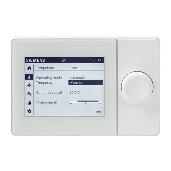
Page 44: Operating Heating/Cooling
Operating mode, temporary temperature adjustment, and time switch program apply in common for heating and cooling. Only the comfort setpoint for heating or cooling is displayed based on mode and can be set. Siemens Graphical User Interface UI400 CE1U2348en Building Technologies... - Page 45 3. Turn the control knob to select another living zone. 4. Press the control knob to confirm the selected living zone. a Information and settings for the selected living zone is now displayed below the dash. Siemens Graphical User Interface UI400 CE1U2348en Building Technologies...
- Page 46 2. Press the control knob. The operating mode setting is selected and is displayed inverted. 3. Turn the control knob to select another operating mode setting. 4. Press the control knob to confirm the setting. Siemens Graphical User Interface UI400 CE1U2348en Building Technologies...
- Page 47 2. Press the control knob. The comfort setpoint setting is selected and is displayed inverted. 3. Turn the control knob and set the desired comfort temperature. 4. Press the control knob to confirm the setting. Siemens Graphical User Interface UI400 CE1U2348en Building Technologies...
- Page 48 10. Press the control knob to confirm the stop time. The phase is once again preselected (frame around the phase). Delete phases Set the start and stop time to the same time to delete a phase. Siemens Graphical User Interface UI400 CE1U2348en Building Technologies...
- Page 49 4. Press the control knob to confirm the selected day. The daily program is overwritten. 5. Repeat overwrite of daily programs for all desired days. 6. Conclude copy function with "Done". Siemens Graphical User Interface UI400 CE1U2348en Building Technologies 2014-06-03...
-
Page 50: Operate Ventilation
Operating mode. – Whether boost ventilation is active. – The time program for the present day. Functions in Automatic mode. The time program is available exclusively to the Automatic operating mode. Siemens Graphical User Interface UI400 CE1U2348en Building Technologies 2014-06-03... - Page 51 It is easier to use the plant/zone switch on the start page if you want to operate the entire building in automatic mode. To change operating mode, proceed in the manner as described for the temperature page. Siemens Graphical User Interface UI400 CE1U2348en Building Technologies...
- Page 52 Phases are defined in the time program during which the living zone is actively used. The living zone is ventilated during these phases at the comfort stage. To change the time switch program, proceed in the manner as described for the temperature page. Siemens Graphical User Interface UI400 CE1U2348en Building Technologies 2014-06-03...
-
Page 53: Operate Hot Water
– The time program for the present day. Functions in operating mode "On". Nominal setpoint setting and time program are normally available in operating mode "On" (depending on the controller configuration). Siemens Graphical User Interface UI400 CE1U2348en Building Technologies 2014-06-03... - Page 54 1. Turn the control knob until the temporary setting is preselected. 2. Press the control knob. The temporary setting is selected and is displayed inverted. 3. Turn the control knob to temporarily recharge. 4. Press the control knob to confirm "Recharge". Siemens Graphical User Interface UI400 CE1U2348en Building Technologies 2014-06-03...
- Page 55 The phases are defined in the time switch program during which hot water is provided. Hot water is heated to the nominal setpoint during these phases. To set the time program for hot water, proceed in the manner as described for the temperature page. Siemens Graphical User Interface UI400 CE1U2348en Building Technologies 2014-06-03...
-
Page 56: Evaluate Plant And Set
Basic navigation Basic navigation on the navigation bar and work area for the following menus is described in Section "Operation [➙ 36]", section "Navigate and set with the control knob". Siemens Graphical User Interface UI400 CE1U2348en Building Technologies 2014-06-03... -
Page 57: Evaluate And Operate Info
Message pages are only displayed if messages are pending. The message pages are assigned to the top if messages are pending. Each Info page has a title. Information by topic is displayed separated by a dash. Siemens Graphical User Interface UI400 CE1U2348en... -
Page 58: Operate Messages (Errors, Maintenance Messages)
For interactive sensors, the user must troubleshoot and then reset the sensor (see the following instruction). The error history for the diagnostic pages (see Section "Test plant, diagnostics [➙ 74]") includes timestamps and any additional information on errors. Siemens Graphical User Interface UI400 CE1U2348en Building Technologies... - Page 59 During the reset, the text changes to "Activated" and is preselected. 4. The page is automatically closed if the error is reset. The device address ("Segment.Device") is not displayed on a directly connected controller. Siemens Graphical User Interface UI400 CE1U2348en Building Technologies...
- Page 60 You reset the maintenance messages indirectly by resetting the counter to time clock, or by eliminating the cause of the message. The user's guide for your controller includes additional information on resetting maintenance messages. Siemens Graphical User Interface UI400 CE1U2348en Building Technologies...
-
Page 61: Plant Information
The scope of the displayed plant pages is adapted to actual plant configuration. ● Only zones assigned to the plant pages are displayed. ● The plant pages have no operating elements. Siemens Graphical User Interface UI400 CE1U2348en Building Technologies 2014-06-03... - Page 62 4. Continue to turn the control knob to go to other plant pages. 5. Press the control knob to preselect the title of a plant page. 6. Exit Info pages with the back arrow. Siemens Graphical User Interface UI400 CE1U2348en...
-
Page 63: Energy Consumption
7. Press the control knob to select the time frame. 8. Turn the control knob to change to 8 days, 12 months, or 10 years. 9. Exit Info pages with the back arrow. Siemens Graphical User Interface UI400 CE1U2348en Building Technologies... -
Page 64: Operating Service/Setting
4. Expert: Login to expert view. Structure A topic list is displayed in the work area when selecting service/setting pages. The entries can be individually selected. The actual service/setting pages open. Siemens Graphical User Interface UI400 CE1U2348en Building Technologies 2014-06-03... -
Page 65: Regional Settings
5. Turn the control knob and enter the value. 6. Press the control knob to confirm the settings. The value is once again preselected. 7. Go to the title for additional regional settings or exit regional settings with "Back". Siemens Graphical User Interface UI400 CE1U2348en Building Technologies 2014-06-03... -
Page 66: Operate Special Functions
Section "Special operations [➙ 94]" includes special operations and special functions sorted by controller type. ● The technical background on special operations and special functions is provided in the user's guide for your controller. Siemens Graphical User Interface UI400 CE1U2348en Building Technologies 2014-06-03... - Page 67 The floor curing function is now activated, visible on the service special operation symbol ( ) on the status bar. Deactivate Deactivate the floor curing function by setting the status for "Floor curing zone 1" to "Off". Siemens Graphical User Interface UI400 CE1U2348en Building Technologies 2014-06-03...
-
Page 68: Set Important Plant Parameters
5. Push and turn the control knob to go to the work area of a setting page. 6. Set the values as per the needs of your building or living zone. 7. Exit the settings page with "Back". Siemens Graphical User Interface UI400 CE1U2348en... -
Page 69: Login To Expert View
5. Press the control knob to confirm selection. 6. You receive feedback on successful login that you confirm with "Continue". a The user symbol ( ) with the corresponding level is displayed on the status bar. Siemens Graphical User Interface UI400 CE1U2348en Building Technologies... - Page 70 5. Do the same for the 5 digits of the OEM password. 6. You receive feedback on successful login that you confirm with "Continue". a The user symbol ( ) with the corresponding level is displayed on the status bar. Siemens Graphical User Interface UI400 CE1U2348en Building Technologies...
-
Page 71: Commission Plant Using The Commissioning Wizard
The entire room/operating-specific part as well as chapter or sub-chapter of the plant-specific part can be repeated (in graphic: Redo). The chapter or sub-chapter of the plant-specific part can be skipped (in graphic: Skip). Siemens Graphical User Interface UI400 CE1U2348en Building Technologies... - Page 72 Commission plant using the commissioning wizard Siemens Graphical User Interface UI400 CE1U2348en Building Technologies 2014-06-03...
-
Page 73: Analyze Plant And Set
The expert view is presented in the same way for room units or operator units. Basic navigation Basic navigation on the navigation bar and work area for the following menus is described in Section "Operation [➙ 36]", section "Navigate and set with the control knob". Siemens Graphical User Interface UI400 CE1U2348en Building Technologies 2014-06-03... -
Page 74: Test Plant, Diagnostics
The user's guide for the controller includes detailed information on the individual diagnostic and test parameters. Operating and use of diagnostic pages is illustrated below using the input/output test as an example. Siemens Graphical User Interface UI400 CE1U2348en Building Technologies... -
Page 75: Example Input/Output Test
1. Press the control knob to go to the work area. 2. Turn the control knob until the setting value for "Output test UX1" is highlighted. 3. Press the control knob to select the test value. Siemens Graphical User Interface UI400 CE1U2348en... - Page 76 "Unused". 4. Go to the title of the diagnostics page to conduct additional diagnostics or select "Back" to return to the topic list. Siemens Graphical User Interface UI400 CE1U2348en Building Technologies...
-
Page 77: Set Plant And Troubleshoot
"Complete parameter list" or commissioning wizard that impact the device pages. Structure A topic list is displayed in the work area when selecting Adjust/repair pages. The entries can be individually selected. The actual Adjust/repair pages open. Siemens Graphical User Interface UI400 CE1U2348en Building Technologies... -
Page 78: Complete Parameter List
The user's guide for your controller includes an overview table and detailed explanations on all parameters. Hint A long press of the knob (> 3 seconds) jumps from any page to the "Expert view start page" (diagnostics page). Siemens Graphical User Interface UI400 CE1U2348en Building Technologies 2014-06-03... - Page 79 8. Turn the control knob within a topic to go to other parameter list pages. 9. Go to the work area to make the settings or exit the parameter list pages with "Back". Siemens Graphical User Interface UI400 CE1U2348en Building Technologies...
-
Page 80: Start Commissioning Wizards
Proceed as follows to start the commissioning wizard: From the topic list, select "Commissioning wizard" and confirm the selection. Notes on plant parameters are available in the user's guide for your controller. Siemens Graphical User Interface UI400 CE1U2348en Building Technologies... -
Page 81: Update Operator Unit
If a change is made to the configuration of a room unit or operator unit that relates to the entire plant (e.g. heating circuit 2 "On"), all devices on the plant must be updated prior to hand off to the end user. Siemens Graphical User Interface UI400 CE1U2348en... -
Page 82: Technical Data
Safety class III (for proper installation) Housing Protection as per EN 60529 IP40 - Mounted Standards, guidelines Electromagnetic compatibility For residential, commercial, and industrial environments. (application range) EU conformity (CE) T7471x5 Siemens Graphical User Interface UI400 CE1U2348en Building Technologies 2014-06-03... - Page 83 RAL 9003 (signal white). Dimensions Width x Height x Depth 144 x 96 x 20.0 (27.6 with control knob) mm Weight Without/with packaging QAA74.611: 228 / 288 g QAA74.614: 231 / 291 g Siemens Graphical User Interface UI400 CE1U2348en Building Technologies 2014-06-03...
-
Page 84: Avs74
Weight Without/with packaging * AVS74.261: 219 / 276 g AVS74.661: 214 / 271 g AVS74.761: 221 / 278 g * AVS74 devices are in multipacks. As a share of packaging weight. Siemens Graphical User Interface UI400 CE1U2348en Building Technologies 2014-06-03... -
Page 85: Additional Information
Additional information 10 Additional information Documentation landscape This user's guide is a component of the Albatros2 documentation landscape. Documentation type Contents Controller hardware and parameter description User guides for Albatros2 controllers [code letter U] e.g. "Hydraulic partial diagrams and supplemental functions"... -
Page 86: Appendix
°C Room temperature max °C Readjustment room sensor (Temperature). -3.0 +3.0 °C Room humidity Readjustment room sensor (Humidity). * Operating lines available on QAA74 only ** AVS74: Only operator units 1...3 Siemens Graphical User Interface UI400 CE1U2348en Building Technologies 2014-06-03... - Page 87 Missing ¦ In operation ¦ No recept'n ¦ Change batt Delete all devices No ¦ Yes * Operating page "RF" is only displayed if the system has at least one RF participant. Siemens Graphical User Interface UI400 CE1U2348en Building Technologies...
-
Page 88: Settings In Detail
The value is set to off after initial commissioning. Off* The entire commissioning wizard or the chapter specific to the operator unit is switched off. * Impact depends on controller Siemens Graphical User Interface UI400 CE1U2348en Building Technologies 2014-06-03... - Page 89 Operating line 40 Room unit 1 Operating line 42 Zone 1 and 2 Operating line 47 Zone 1 only Operating line 48 Zone 1 only Unit 2 Operating line 40 Room unit 2 Siemens Graphical User Interface UI400 CE1U2348en Building Technologies 2014-06-03...
- Page 90 Operation acts jointly on zone 1 and 2. Zone 1 is displayed. Independently A zone can be selected in operation. Operation of Zone 3 See "Operation of Zone 2" (operating line 44). (operating line 46) Siemens Graphical User Interface UI400 CE1U2348en Building Technologies 2014-06-03...
- Page 91 Zone 1 and 3 All zones Room unit 2 Room unit 3 Operator unit 1 Zone 1 Zone 1 and 2 Zone 1 and 3 All zones Operator unit 2 Operator unit 3 Siemens Graphical User Interface UI400 CE1U2348en Building Technologies 2014-06-03...
- Page 92 * Operating lines only available on QAA74. QAA74 must be configured as room unit. Display of room values (temperature, humidity). The temperature and humidity displays can be corrected. Device data Operating line Settings Software version Present version of the room/operator unit. Siemens Graphical User Interface UI400 CE1U2348en Building Technologies 2014-06-03...
- Page 93 Missing ¦ In operation ¦ No recept'n ¦ Change batt Delete all devices No ¦ Yes Delete all devices The radio link to all devices will be cancelled. If radio communication is required again, a new binding must be established. Siemens Graphical User Interface UI400 CE1U2348en Building Technologies 2014-06-03...
-
Page 94: Special Operations
The function is activated. 2. Conclude the function with "Eco mode" = "Off". Depending on the controller, the energy savings function Eco mode is displayed without the maintenance/special operating symbol is displayed. Siemens Graphical User Interface UI400 CE1U2348en Building Technologies... - Page 95 [➙ 66]". 1. Press and hold the control knob. a The function is active. The additional operating line "Boiler temperature" is displayed. 2. End the function by releasing the control knob. Siemens Graphical User Interface UI400 CE1U2348en Building Technologies 2014-06-03...
-
Page 96: Manual Operation
1. Select "Floor curing function" = "Manual". The additional Info line "Present floor curing setpoint"" is displayed. 2. Enter the "Present floor curing setpoint". 3. Conclude the function with "Floor curing function" = "Off". Siemens Graphical User Interface UI400 CE1U2348en Building Technologies... - Page 97 [➙ 66]". 1. Select "Controller stop function" = "On". The function is activated. The additional operating line "Controller stop setpoint" is displayed. 2. Conclude the function with "Controller stop function" = "Off". Siemens Graphical User Interface UI400 CE1U2348en Building Technologies 2014-06-03...
- Page 98 Additional information on the defrost function is available in the user's guides for your controller. Procedure w Navigation to special operation menu is described in Section "Operate special functions [➙ 66]". Select "Initiate defrost" = "Yes". Siemens Graphical User Interface UI400 CE1U2348en Building Technologies 2014-06-03...
-
Page 99: Unlock Button On Boiler Management Units
2. You unlock the LMS14/15 again using the unlock button, by holding it down between 0.4...10 seconds. The unlocking button executes the same function as switching of LMS input "Reset" (X4/X4a). Siemens Graphical User Interface UI400 CE1U2348en Building Technologies 2014-06-03... - Page 100 Issued by © 2014 Copyright Siemens Switzerland Ltd Siemens Switzerland Ltd Technical specifications and availability subject to change without notice. Infrastructure & Cities Sector Building Technologies Division International Headquarters Gubelstrasse 22 CH-6301 Zug Tel. +41 41-724 24 24 www.siemens.com/buildingtechnologies Document ID...