Table of Contents
Advertisement
Quick Links
Advertisement
Table of Contents
Troubleshooting

Related Manuals for Siemens CIM


Summary of Contents for Siemens CIM
- Page 1 Preface Application and functions Structure of the device Security Mounting and connecting the device Web-based configuration Operating Manual CIM SGLAN Connector Practical example Dimension drawing Technical specifications Technical support 11/2022 A5E51250518-AC...
- Page 2 Note the following: WARNING Siemens products may only be used for the applications described in the catalog and in the relevant technical documentation. If products and components from other manufacturers are used, these must be recommended or approved by Siemens. Proper transport, storage, installation, assembly, commissioning, operation and maintenance are required to ensure that the products operate safely and without any problems.
-
Page 3: Preface
Product names and abbreviations • CIM or device In this document, the term "CIM" or "device" is also used instead of the full product name "CIM“. CIM is the abbreviation for Communication Interface Module. Use of the device... -
Page 4: Table Of Contents
Table of contents Preface ..............................3 Application and functions ........................7 What's new in CIM 1.1? ......................7 Functions ..........................8 Requirements for use ......................10 Universal Data Model ......................11 SGLAN ..........................14 Accessories ........................15 Structure of the device ........................16 Appearance of the device .................... - Page 5 5.4.10.5 System configuration management..................86 5.4.10.6 System upgrade ......................... 86 CIM SGLAN Connector ......................... 88 Installation ........................89 Working with CIM SGLAN Connector .................. 90 6.2.1 Certificate setting ......................90 6.2.2 Server list .......................... 91 6.2.3 Connecting to SGLAN server ....................92 6.2.4...
- Page 6 Table of contents 7.1.1 Fill control ......................... 94 SGLAN example ......................... 95 7.2.1 Download program to LOGO! BM remotely................. 95 7.2.2 Download Network project with LOGO!Soft Comfort remotely .......... 101 Dimension drawing ........................... 111 Technical specifications ........................112 Technical specification ..................... 112 Certificates and approvals ....................
-
Page 7: Application And Functions
– SGLAN (Page 14) (Secured Global Local Area Network) is used for setting up virtual LAN for devices from different sites – Siemens CIM SGLAN Connector: application for connecting PC to SGLAN as SGLAN client – SGLAN page (Page 49) on CIM web-based configuration •... -
Page 8: Functions
4 devices to CIM through Ethernet switch ports. General gateway CIM can access the Internet with cellular module and SIM card. LOGO! BM or Modbus RTU compatible devices can access the internet by connecting to CIM. Operating Manual, 11/2022, A5E51250518-AC... - Page 9 – Enable/disable map the position data to UDM • Time Server – CIM can act as an NTP server to provide time for LOGO! BM or other NTP client. – CIM can enable/disable mapping the time to the Universal Data Model (UDM). Then the device without NTP can get the time via multi-protocol or RESTful API.
-
Page 10: Requirements For Use
Requirements for operation • Cellular module (mini PCIe) To operate the CIM in its entirety, you require a cellular module that is compatible to CIM and the standard of the cellular network you are using. For more information, refer to the section Slots for SIM card and cellular module (Page 18). -
Page 11: Universal Data Model
For more information, refer to the section Cellular settings (Page 76). Compatible cards The card receptacle of the CIM for the SIM card is compatible with the following card formats: • Mini SIM card, 25 x 15 mm (ISO/IEC 7810 ID-000) Universal Data Model “Universal Data Model (UDM)”... - Page 12 Application and functions 1.4 Universal Data Model I, Q, M, V constructed a data model to simulate the process image in PLC. Naming rule for the UDM address: address type + short data type + start address. No byte alignment, for example, VW3 means the word consist of Byte 3 and Byte 4 in area V. The UDM address is case insensitive.
- Page 13 Application and functions 1.4 Universal Data Model System variable SV (System variable) is used to save some system data, such as, position, time, power state, mini PCIe module information and so on. Item Type Size Range Unit comments Sample for Restful dress Interface Time...
-
Page 14: Sglan
CIM V1.1 and later versions. SGLAN SGLAN (secured global local area network) allows you to create a private network with CIM. SGLAN is the fundamental building block for your private network. Devices in the SGLAN can communicate with each other securely. -
Page 15: Accessories
Note Only CIM can work as SGLAN server. Each SGLAN server can connect 2 SGLAN clients maximum. • SGLAN client: after joining the SGLAN, SGLAN client and devices in the same LAN with SGLAN client can communicate with other devices joined SGLAN like in a same LAN. -
Page 16: Structure Of The Device
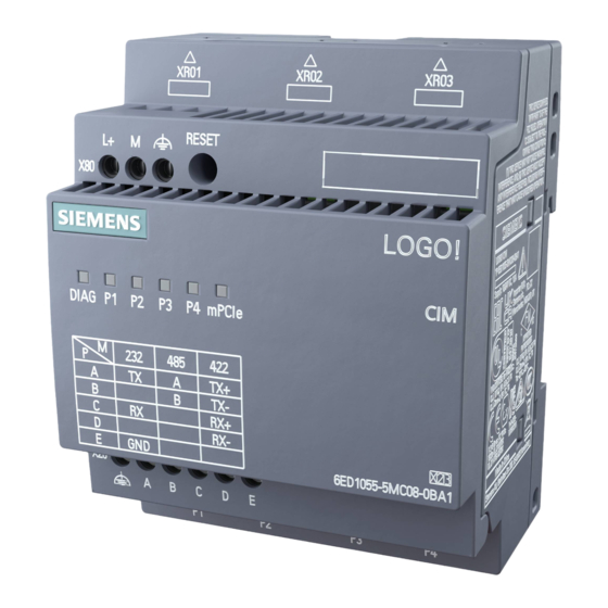
Structure of the device Appearance of the device Front view ① RESET button ② X80 (L+, M, FE) Power supply connector ③ ④ FE terminal for shield cable ⑤ X20 (FE, A, B, C, D, E) Multiplex serial interface ⑥ For more information about the device, scan the QR code Top view ①... -
Page 17: Leds To Display Operation
Mounting interlock for DIN rail Bottom view ① 4 × RJ45 Ethernet 10/100 Mbps LEDs to display operation The LEDs on the CIM provide information about the operating status of the device. Meaning of the LEDs Status Meaning System diag- The LED light is green when CIM is in RUN mode. -
Page 18: The "Reset" Button
Structure of the device 2.3 The "RESET" button Status Meaning Firmware is crashed. Red flashing CIM is powered by capacitor. LAN (P1, P2, P3, Flash Port is receiving or sending data across Ethernet. Port is already connected to Ethernet. No connection to Ethernet. - Page 19 The table shows the approvals that may be available. For the device itself, it is certificated as shown on the product label and package label. Note CIM with Telit series wireless module and SIM7600G-H LTE CAT-4 mPCIe are certified with UL, IECEx,ATEX,FM,RCM. CE-RED: test with wireless module Telit LE910C1-EU LTE CAT-1 mPCIe and SIM7600G-H LTE...
-
Page 20: Security
Siemens' products and solutions undergo continuous development to make them more secure. Siemens strongly recommends that product updates are applied as soon as they are available and that the latest product versions are used. Use of product versions that are no longer supported, and failure to apply the latest updates may increase customers' exposure to cyber threats. -
Page 21: Important Notes On Using The Device
Note Cleaning CIM Requirement: The supply voltages on the CIM is switched off. If you need to clean the devices, use dry ESD cleaning cloths (observing the ESD protective measures). Overvoltage protection... - Page 22 • The output of the external power supply must be short-circuit proof. NOTICE Power supply The external power supply for the CIM must meet the requirements for Safety Extra-Low Voltage (SELV). Note the information in this section and in the installation and operating instructions from the manufacturer of the power supply.
- Page 23 Other measures, such as the use of security policies, should be applied as needed. Note To protect LOGO!Soft Comfort from any undesired manipulation when your PC suffers malicious attacks from the Internet, Siemens strongly recommends you to install a allow list tool on the PC. Operating Manual, 11/2022, A5E51250518-AC...
-
Page 24: Mounting And Connecting The Device
The CIM installation dimensions are compliant with DIN 43880. CIM can be snap-mounted to 35 mm DIN rails according to EN 60715 or mounted on the wall with two M4 screws. - Page 25 Mounting and connecting the device 4.1 Mounting the device Installation position Installation position of the CIM Vertical installation of the CIM Horizontal installation of the CIM Operating Manual, 11/2022, A5E51250518-AC...
-
Page 26: Din Rail Mounting
DIN rail mounting Mounting To mount a CIM onto a DIN rail, follow these steps: 1. Hook the CIM onto the rail. 2. Push down the lower end to snap it on. The mounting interlock at the rear must engage. -
Page 27: Wall-Mounting
2. Feed the screws through the openings in the catches and secure the device to the wall. Note When you do not wall-mount CIM, always keep the mounting slides in the factory default positions, that is, within the data area given in the illustration above; otherwise, the mounting slides may deform if they are exposed to hot and humid surroundings for a long term. -
Page 28: Connecting The Device
Mounting and connecting the device 4.2 Connecting the device Drilling template for wall-mounting Before you can wall-mount CIM, you need to drill holes using the template shown below: All dimensions in mm Bore hole for M4 screw. Connecting the device 4.2.1... -
Page 29: Connecting The Power Supply And Function Earth
Mounting and connecting the device 4.2 Connecting the device CAUTION Use copper cables at connectors with terminal connections Use copper (Cu) cables for all supply lines that are connected to the device with terminals, e.g. 24 VDC power supply cables to the 24 VDC power supply connectors. Utiliser des câbles en cuivre sur les connexions à... - Page 30 • Is achieved efficiently by a connection to the DIN rail. Note Power supply unit of the CIM is not electrically isolated No electrical isolation means that the input and output circuits are not galvanically isolated. Operating Manual, 11/2022, A5E51250518-AC...
-
Page 31: Connecting The Lan Interface
Connecting the LAN interface Connect your local area network, the PC or the BM to interface X1IE (LAN connection) of the CIM. The interface supports autonegotiation and autocrossing. For the connection, use a patch cable with an RJ-45 plug. For the requirements and for information on grounding see below. - Page 32 Mounting and connecting the device 4.3 Installing expansion modules NOTICE Electrostatic sensitive devices (ESD) The device contains electronic components that may be destroyed by electrostatic charges. This can result in malfunctions and damage to the machine or plant. Take corresponding precautionary measures before you open the device. Exploded view ①...
- Page 33 Mounting and connecting the device 4.3 Installing expansion modules Press the marked recesses on both left and right sides of the module with a flat-blade screwdriver to loosen and then remove the middle housing. Open the top housing Pull the top housing in the marked direction to open the cover. Operating Manual, 11/2022, A5E51250518-AC...
-
Page 34: Installing The Sma Connector
Mounting and connecting the device 4.3 Installing expansion modules 4.3.2 Installing the SMA connector Requirement • The device is disconnected from the power supply and the DIAG LED goes out. Procedure Follow the steps to install the SMA connector. 1. Press the marked recesses on both left and right sides of the module with a flat-blade screwdriver to loosen and then remove the middle housing. -
Page 35: Insert The Sim Card
Mounting and connecting the device 4.3 Installing expansion modules 3. Install the SMA connector as the marked order into the hole. 4. Install the middle housing back on the bottom housing. When install the middle housing, place the bottom of the SMA connectors below the top PCBA first, then adjust the position of the middle housing and install it back. - Page 36 Mounting and connecting the device 4.3 Installing expansion modules 1. Pull the top housing in the marked direction to open the cover. 2. Unlock the card holder in the marked direction. 3. Put the SIM card in the card holder and then lock the card holder in the marked direction. 4.
-
Page 37: Installing The Cellular Module
Mounting and connecting the device 4.3 Installing expansion modules Uninstall the SIM card Unlock the card holder to remove the SIM card, and then lock the card holder as the default status. 4.3.4 Installing the Cellular module Note Power consumption If the power consumption of the cellular module is too high, the device will be damaged. - Page 38 Mounting and connecting the device 4.3 Installing expansion modules Install the cellular module 1. Open the top housing. 2. Insert the cellular module into the socket from the bottom side. 3. Press the cellular module in the marked direction to lock the cellular module. 4.
-
Page 39: Connecting The Antenna
20 cm distance from a human body. The CIM has three antenna sockets of the type SMA for connecting the antennas. The antennas must have an impedance of approx. 50 Ω. - Page 40 Mounting and connecting the device 4.3 Installing expansion modules Name MLFB Remarks Antenna 6GK5895-6ML00- Antenna ANT 895-6ML, active GNSS antenna 0AA0 6GK5896-4ME00- Cylinder shaped antenna ANT 896-4ME for GSM (2G), UMTS 0AA0 (3G) and LTE (4G), ANT896-4ME 6GK5896-4MA00- IRC antenna ANT 896-4MA for GSM (2G), UMTS (3G) and 0AA3 LTE (4G),ANT896-4MA Operating Manual, 11/2022, A5E51250518-AC...
-
Page 41: Web-Based Configuration
• Do not connect the device directly to the Internet. Operate the device within a protected network area. • Keep the firmware up to date. Check regularly for security updates of the firmware and use them. • Check regularly for new features on the Siemens Internet pages. – Network security information (https://new.siemens.com/global/en/products/automation/topic-areas/industrial- security.html) Physical access Restrict physical access to the device to qualified personnel. -
Page 42: Downloading And Installing The Certificate
Downloading and installing the certificate 5.2.1 Overview CIM has a build-in Web-based configurator which enables you to configure the CIM functions from a PC. CIM supports HTTPS for web server communication. You need to import the LOGO! Root certificate before using HTTPS to visit CIM with browsers. -
Page 43: Installing The Certificate For Windows
Web-based configuration 5.2 Downloading and installing the certificate 5.2.2 Installing the certificate for Windows Install the certificate for Windows 1. Double click the certificate to start the installation. 2. Check the certification information in the pop-up window, then click "Install Certificate" to continue. -
Page 44: Installing The Certificate For Mac Os
Web-based configuration 5.2 Downloading and installing the certificate 5.2.3 Installing the certificate for Mac OS Install the certificate for MAC OS 1. Open the Keychain. 2. To add a certificate, select "system" ① , then click "+"②. 3. Select the certificate of CA, then click "Open" to add it. 4. -
Page 45: Accessing Web-Based Configuration From Pc
Accessing web-based configuration from PC To access the CIM Web-based configuration from a PC, follow these steps: 1. Ensure that the CIM and the PC are on a common Ethernet network or are connected directly to each other with a standard Ethernet cable. - Page 46 Web-based configuration 5.3 Accessing web-based configuration from PC 5. Click or tap "①" to view the OSS Readme. 6. Click or tap "③" to log in to the Web server. If you do not desire to enter the user name and password again at the next logon, you can select the "②"...
-
Page 47: Web
④ Detailed information of a specific web page. Configuration pages The CIM includes following configuration pages: Configuration pages Description Device information Display the general information of the connected CIM SGLAN Set the SGLAN connection for CIM LAN settings Set the LAN for CIM Contacts... -
Page 48: Device Information
The Device information page displays the general information of the connected CIM. Parameters Meaning Device name Display the device name. By clicking "Name", you can edit the CIM name. FW version Firmware version of CIM Boot version Boot version of CIM... -
Page 49: Lan Settings
5.4.3 LAN settings This page allows you to set the IP for CIM. If you forget the password for login, you need to reset the CIM to factory setting (Page 18) and log in with the default password. 5.4.4 SGLAN Setting 5.4.4.1... -
Page 50: Setting Up Sglan Client
Internet through IPv4/IPv6 • The SIM card in CIM supports sending and receiving short message if you set up SGLAN by • The IP of the devices in SGLAN are in the same subnet and not conflict with each other Requirement •... - Page 51 – If you select "IPv4/IPv6", enter the server IP address of the CIM server. – If you select "SMS_v4/SMS_v6", enter the phone number of the CIM server. 4. Enter the access password of CIM server in the input field next to "Server Password". Note If you have enabled SGLAN server without changing the password, you can connect to the SGLAN server with the default password "sglan".
- Page 52 Web-based configuration 5.4 Web pages 5. Click "Save changes". Connection Status Description Disconnected Not connected to SGLAN Connecting The SGLAN client is connecting to the SGLAN server and setting up SGLAN. Connected The SGLAN is setup and the SGLAN client is connected to SGLAN server. Connect error Failed to establish the communication between SGLAN Client and SGLAN Server...
- Page 53 Web-based configuration 5.4 Web pages Server List The server list allows you add SGLAN server devices you commonly used in it. You can use this server list to quickly connect to the SGLAN server. Create a server item 1. Click "Add Row" button. 2.
-
Page 54: Contacts
5.4.5 Contacts In this table, you can configure the contacts for sending or receiving SMS messages. You can add a maximum of 16 contacts for CIM. Add a contact 1. Click "Add Row". 2. Enter the "Name" and "Phone Number" of the contact. -
Page 55: Data Management
The variable is defined by variable name, data type, address type and address. This chapter shows how to create and edit variables that you use to store values in CIM. You can create variables for all data type UDM permitted. -
Page 56: Messages
5.4.6.2 Messages This page allows you add or edit a message that CIM can send and receive. Add a message 1. Click "Add Row". 2. Enter the title and message text. You can add maximumly 8 messages. A title and message text can contain letters, numbers and special characters. - Page 57 Note If you toggled on "with parameter", the variable value of the bind event will be added in the message CIM sends. If the parameter is in hexadecimal, 0x is also added before the value. • Message content with parameter: message text + value of the parameter.
-
Page 58: Data Binding
This page allows you to bind an event to an action. Refer to Universal Data Model (Page 11) for more information. Event is defined by you. An event can be variable change or receiving message. You can set an action CIM will take when the event you set happens. Operating Manual, 11/2022, A5E51250518-AC... - Page 59 Web-based configuration 5.4 Web pages Bind data 1. Click "Add Row" to add a new row. 2. Click the "Event Type" drop-down list to choose and event. Event Event Source restriction source Changes from 1 to 0 Variable Permitted data type: bool Changes from 0 to 1 Value Changed Permitted data type: all UDM permitted data type ex-...
- Page 60 Web-based configuration 5.4 Web pages 4. Set the action type. Action Action Target restriction Remark source Set new value variable Permitted data type: all UDM permitted data type. Copy value from The variable type of the If the event is "receive mes- event action must be the same as sage"...
-
Page 61: Online Monitor
As the online variables in the online variable page are saved in the browser, you should note the following issues: • Make sure you do not set your browser to private mode when you use CIM online monitor, since your browser does not record any browsing history in this mode. -
Page 62: Protocol Settings
S7 server and S7 client at the same time. Note When you setup S7 communication between a remote device to CIM, make sure S7 communication is enabled in the connected remote device. Operating Manual, 11/2022, A5E51250518-AC... - Page 63 ③ Enable or disable the Dynamic server connection Note: CIM support maximumly four S7 connections simultaneously. If you have set some static connec- tions, the number of the dynamic server connections = 4 - the number of the static connections ④...
- Page 64 • Local TSAP: the TASP in CIM is 00.01 to FF.FF ⑧ Click to open the "Data transfer table" of the corresponding connection that CIM work as a S7 client. Data transfer table configuration For the connections that CIM works as S7 client, you need to configure the data transfer table: 1.
- Page 65 Note You can add maximum of 16 rows most. Data transfer restrictions The table below describes the range and local address restrictions for client connections. Read and Write requests: Local address (CIM) Remote address (S7 compatible device) Address Type Range...
-
Page 66: Modbus Tcp
When you set up Modbus TCP communication between two CIM, do enable S7 connection first. Note When you set up Modbus TCP communication between a remote device to CIM, make sure Modbus TCP communication is enabled in the connected remote device. Operating Manual, 11/2022, A5E51250518-AC... - Page 67 ③ Enable or disable the Dynamic server connection Note: CIM support maximum four Modbus TCP connections simultaneously. If you have set some static connections, the number of the dynamic server connections = 4 - the number of the static connections ④...
- Page 68 Here you configure the properties of the client. • Remote IP: the IP of the server that you want to connect ⑧ Click to open the "Data transfer table" of the corresponding connection that CIM work as a Modbus TCP client. Modbus TCP data transfer configuration...
- Page 69 Web-based configuration 5.4 Web pages Data transfer restrictions The table below describes the range and local address restrictions for client connections. Local address (CIM) Remote address (Modbus TCP com- patible device) Address Type Range Address Type 0.0 to 511.7 Coil Discrete Input (DI) 0.0 to 511.7...
-
Page 70: Modbus Rtu
5.4 Web pages 5.4.7.4 Modbus RTU This page allows you enable, disable and set the Modbus RTU connection. CIM supports only one Modbus RTU connection, either as Modbus RTU master or Modbus RTU slave. ① Enable or disable the Modbus RTU connection Note: Modbus RTU connection is not secure. - Page 71 7. Input the length of the data need to be transferred ⑦. 8. Input the Unit ID of the remote Modbus RTU slave (Slave ID/Address) ⑧. 9. To set the time interval that CIM synchronizes the data with the server, select the check box and input the specified time interval ⑨.
-
Page 72: Restful Api
CIM using an automated or programmed interface. If the device connected to CIM supports RESTful, you can get or put data on UDM through RESTful API. For example, you can access the UDM interface by a Swagger user interface, which contains a detailed description of the classes, methods and parameters. - Page 73 Format for the range: start address~end address. If the range is not set, CIM regards you need the whole range of the address type. – ~end address: if the start address is not set, CIM regards the start address is the start of the range.
- Page 74 Web-based configuration 5.4 Web pages Sample The [address type][type][range] portion with in the examples below can be exchange with any of the allowed parameters. Example Description https://xxx.xxx.xxx.xxx:xxx/pi/rest/ All bits at [5.3, 8.7] in range I ix5.3~8.7 https://xxx.xxx.xxx.xxx:xxx/pi/rest/ All bit in range I https://xxx.xxx.xxx.xxx:xxx/pi/rest/ https://xxx.xxx.xxx.xxx:xxx/pi/rest/ A bit at 5.3 in range I...
-
Page 75: Cellular And Gnss
Web-based configuration 5.4 Web pages 5.4.8 Cellular and GNSS 5.4.8.1 Cellular status This page displays the current cellular network status. Cellular status Items Meaning SIM card Plugged in / Not plugged in SIM card status Ready / Not Ready Provider Display the provider of the SIM card SIM card number Display the phone number of the SIM card... -
Page 76: Cellular Settings
3. Click the "Test" button. Note This test is for the connection of CIM to a specified destination device, but not for the PC. Restart cellular module You can restart the cellular module by clicking the "Restart Cellular Module" button. -
Page 77: Extra Initialization Commands
Web-based configuration 5.4 Web pages Advance setting After enabling the advance setting, you can set the APN and Dial number for CIM: APN: Access Point Name Dial number: access code to the dial-up network. SMS Center Number You can set the SMS center number in this field. -
Page 78: Certificates
CIM cannot work as either a server or a client. Note RESTful API has no authentication RESTful API is not safe. If you enabled the RESTful API, a device can connect to CIM by Restful API without authentication. Only enable the RESTful API when needed. - Page 79 2. Click "Download" to download LOGO Root CA. Get the CIM internal certificate CIM can generate certificate for itself. 1. Select CIM internal certificate by selecting the check box next to it. 2. Click "Generate" to generate CIM CA. 3. Click "Download" to download CIM CA.
- Page 80 To build the SGLAN, you need to select the same trusted certificate in both server and client. CIM Build-in certificate is the default solution. Note Make sure the certificate you import to CIM client is in the validity period. Certificate solution Source...
- Page 81 2. Drag and drop or select your own CA to the target file in the page. 3. Click "Import New External Certificate" to import the CA to CIM. 4. Click "Save Changes" to save the change or click "Discard Changes" to discard the change.
-
Page 82: Ip Address Management
5.4 Web pages 5.4.9.3 IP address management If you enable this function, only contacts stored in CIM can query the IPv4/IPv6 address of SIM card through SMS. Otherwise, anyone can query the IPv4/IPv6 address of SIM card through SMS. Get IP address by SMS Note Make sure your SIM card support SMS if you use SMS to query IPv4 or IPv6 address. -
Page 83: System Settings
The page may be stuck for a few seconds during the certificate generation. Note If the time of CIM and PC is different more than 1 year, you will get a notice that you certificate is invalid. Set the time in web-based configuration for CIM. - Page 84 When you selected a sync source, CIM will sync time from the sync source periodically. Note Last sync time The last sync time is the latest time CIM updated. It can be the time synchronized from NTP server or the time you set manually in time setting. Summer/Winter Time...
-
Page 85: Power On/Off Sms
If you didn't change the password, you can log on with the default password "cim". Siemens strongly recommend you change your default password after you first login CIM. If you forget the password, you need to reset the CIM to factory setting (Page 18) and log on with the default password. -
Page 86: System Configuration Management
Built-in certificate (Page 78) and SMS center number (Page 76) will be kept after the factory reset. 5.4.10.5 System configuration management This function allows you export the current CIM configuration or import a CIM configuration file to CIM. Export configure file 1. Click the button "Export Configure File". - Page 87 (https://support.industry.siemens.com/cs/start?lc=en-US). Upgrade the firmware Note • Upgrade firmware will not change any configuration. However, Siemens recommends you backup configuration data through the path System Setting --> System Configuration Management before the upgrading. • In the upgrade environment, other functions of the system are stopped, such as network communication, data bindings and so on.
-
Page 88: Cim Sglan Connector
Information area To connect SGLAN, perform these steps: 1. Install CIM SGLAN Connector (Page 89) 2. Select the certificate (Page 90) (If SGLAN server uses the CIM build-in certificate, skip this step) 3. Connect to SGLAN Server (Page 92) Operating Manual, 11/2022, A5E51250518-AC... -
Page 89: Installation
• You have administrator privileges on your host computer with Windows 10 OS • You have downloaded the installation package. Procedure To install CIM SGLAN Connector, follow these steps: 1. Double-click the file “CIMSGLANConnector_Setup_X64.exe”. The "Welcome to InstallShield wizard for CIM SGLAN Connector" dialog opens. -
Page 90: Working With Cim Sglan Connector
Before connecting the SGLAN server, make sure you select the same trust certificate as the SGLAN server. • If the SGLAN server used the CIM build-in certificate, skip this step. CIM SGLAN connector uses CIM build-in certificate by default. • If the SGLAN server used an "CIM Internal certificate" or "External certificate", you need to upload the same certificate in SGLAN connector before connecting SGLAN server. -
Page 91: Server List
CIM SGLAN Connector 6.2 Working with CIM SGLAN Connector 3. Click "Import New External Certificate" to import the CA. 4. Select External certificate by selecting the check box next to it. 5. Click "Save Changes" to save the change. 6.2.2 Server list The server list records all the SGLAN server devices you added. -
Page 92: Connecting To Sglan Server
Connect to SGLAN server To connect the CIM SGLAN server, follow the steps: 1. Open CIM SGLAN Connector from the start menu or desktop. 2. Select the host mode the same as SGLAN server mode. 3. Enter the IP address of SGLAN server and the access password. -
Page 93: Viewing Sglan Connection
6.2 Working with CIM SGLAN Connector Connect to SGLAN server stored in server list If you stored the information of SGLAN server in the CIM SGLAN Connector, you can connect to SGLAN server as follows: 1. Open CIM SGLAN Connector from the start menu or desktop. -
Page 94: Practical Example
Practical example Application example 7.1.1 Fill control Requirements for a fill system This example illustrates a fill system. We want to monitor and control the whole system anywhere through a web browser. We want to be informed with short message if the liquid level is abnormal. -
Page 95: Sglan Example
Practical example 7.2 SGLAN example Setup We need a CIM to connect the onsite devices. The onsite devices can be LOGO! BM or Modbus RTU devices. LWE project on AWS Could For how to create and deploy a LWE project on AWS Cloud, refer to "LOGO! Web Editor Online Help". - Page 96 • CIM and host computer can access the internet via SIM card • Host computer has Siemens CIM SGLAN Connector installed • You selected the same trust certificate as the SGLAN server in Siemens CIM SGLAN connector Setting up the server 1.
- Page 97 7.2 SGLAN example 3. Test the connection to Internet by pressing "Test Connection (Page 75)". 4. Go to the SGLAN page and enable "CIM as SGLAN Server". Write down the Server IP address. You will need it to configure the client.
- Page 98 Practical example 7.2 SGLAN example Connecting to SGLAN server 1. Open the CIM SGLAN Connector on your host PC. 2. Select the remote host mode. 3. Enter the Server IP address you want to connect. 4. Enter the access password.
- Page 99 Practical example 7.2 SGLAN example Download the program on host computer to LOGO! BM 1. Test the connection to remote LOGO! BM on host computer. Operating Manual, 11/2022, A5E51250518-AC...
- Page 100 Practical example 7.2 SGLAN example 2. Open the program needs to be download with LOGO!Soft Comfort on host computer, and click "Download". 3. Set the communication interface as "SGLAN Virtual Adapter" and Click "OK". Result: The data transfer starts. Operating Manual, 11/2022, A5E51250518-AC...
-
Page 101: Download Network Project With Logo!Soft Comfort Remotely
Practical example 7.2 SGLAN example 7.2.2 Download Network project with LOGO!Soft Comfort remotely This example shows an SGLAN using CIM to realize data transmission between devices distributed in different sites. The sketch below illustrates how such a system works: Requirement •... - Page 102 3. Test the connection to Internet by pressing "Test Connection (Page 75)". 4. Go to the SGLAN page and enable "CIM as SGLAN Server". 5. Set the mode. You can select mode as IPv4 or IPv6. We select mode as IPv6 in this example.
- Page 103 Write down the access password. You will need it to configure the client. Setting up the SGLAN client 1. Access the web-based configuration (Page 45) of CIM as SGLAN client. 2. Check the cellular status. 3. Go to the SGLAN page and enable "CIM as SGLAN Client".
- Page 104 7. Click "Save changes". Download the Network project with LOGO!Soft Comfort 1. Connect the host PC to the CIM server with an Ethernet cable. 2. Access the web-based configuration (Page 45) of CIM server. 3. Go to the SGLAN page and check the connection status.
- Page 105 Practical example 7.2 SGLAN example 5. Set the data transfer in S7 connection. 6. Click download and select the local adapter connected to the CIM as interface. Operating Manual, 11/2022, A5E51250518-AC...
- Page 106 Practical example 7.2 SGLAN example 7. Select the target device in "Accessible LOGO" and click "OK". Operating Manual, 11/2022, A5E51250518-AC...
- Page 107 Practical example 7.2 SGLAN example 8. Open the project for LOGO! BM2 with LOGO!Soft Comfort. Set the data transfer in S7 connection. Operating Manual, 11/2022, A5E51250518-AC...
- Page 108 Practical example 7.2 SGLAN example 9. Click "download". Operating Manual, 11/2022, A5E51250518-AC...
- Page 109 Practical example 7.2 SGLAN example 10.Open LOGO!Comfort on host PC and enter new values on to the address on LOGO! BM1. Operating Manual, 11/2022, A5E51250518-AC...
- Page 110 Practical example 7.2 SGLAN example 11.Check if the data transferred to LOGO! BM2. See also Accessing web-based configuration from PC (Page 45) Operating Manual, 11/2022, A5E51250518-AC...
-
Page 111: Dimension Drawing
Dimension drawing All dimensions in millimeters Operating Manual, 11/2022, A5E51250518-AC... -
Page 112: Technical Specifications
Technical specifications Technical specification Technical specifications - CIM Article numbers 6ED1055-5MC08-0BA2 Attachment to Industrial Ethernet Interface X1P1-P4 for local applications Quantity Design RJ-45 jack Properties 10/100-Base-T, autocrossover, autonegotiation Transmission speed 10 / 100 Mbps Permitted cable lengths (Ethernet) (Alternative combinations per length range) * 0 ... -
Page 113: Certificates And Approvals
The following shows the approvals that may be available. For the device itself, it is certificated as shown on the product label and package label. ISO 9001 certificate The Siemens quality management system for all production processes (Development, Production, Sales and Service of Automation Products, -Systems and -Solutions) meets the requirements of ISO 9001:2015 This has been certified by DQS (the German society for the certification of quality management systems). - Page 114 Technical specifications 9.2 Certificates and approvals CE marking The product meets the requirements and safety objectives of the following EC directives and it complies with the harmonized European standards (EN) for programmable logic controllers which are published in the official documentation of the European Union. •...
- Page 115 Avis Canadian Cet appareil numérique de la classe B est conforme à la norme NMB-003 du Canada. Responsible party for Supplier's Declaration of Conformity Siemens Industry, Inc. Digital Factory - Factory Automation 5300 Triangle Parkway, Suite 100 Norcross, GA 30092 Mail to: (amps.automation@siemens.com)
- Page 116 • This equipment is suitable for use in Class I, Division 2, Groups A, B, C, D; Class I, Zone 2, Group IIC; or non-hazardous locations. IECEx The CIM meet the requirements of explosion protection according to IECEx. IECEx classification: Ex ec IIC T4 Gc IECEx certificate: IECEx UL 22.0089X...
- Page 117 Technical specifications 9.2 Certificates and approvals The CIM meets the requirements of the following standards: • IEC 60079-0, Edition 7 + Corr. 1 Hazardous areas - Part 0: Equipment - General requirements • IEC 60079-7, Edition 5.1 Explosive atmospheres - Part 7: Equipment protection by increased safety «e»...
- Page 118 UK Conformity Assessed marking CIM complies with the designated British standards (BS) for programmable logic controllers published in the official consolidated list of the British Government. CIM meets the requirements and protection targets of the following regulations and related amendments: •...
- Page 119 9.2 Certificates and approvals Recycling and Disposal You can fully recycle CIM due to their low-pollutant equipment. For environmentally friendly recycling and disposal of your old equipment, contact a certified electronic waste disposal company and dispose of the equipment according to the applicable regulations in your country.
-
Page 120: Technical Support
Please check regularly if updates and hotfixes are available for download to your device. The download area is available on the Internet at the following link: After Sales Information (https://support.industry.siemens.com/) Troubleshooting This chapter provides you with tips on how to locate and/or troubleshoot problems. - Page 121 S7 is disabled for BM. through CIM Cellular module When your CIM cannot send SMS or access the Internet, please log into the CIM web-based configuration and check the cellular status in Cellular & GNSS -> Cellular Status. Item Status...
- Page 122 If the SIM card still cannot be registered, try the follow- ing: • power off the CIM for more than two hours • change a CIM card or cellular module The SIM card is locked by your telecom Contact your provider to unlock it.
-
Page 123: Sglan Troubleshooting
SGLAN server or SGLAN client cannot send or receive SMS Cannot get reply when The network quality is poor or the SMS is Place your CIM in a place where mobile signal is querying the IP ad- delayed. strong. dress of CIM... -
Page 124: Index
Cellular settings GNSS settings, 77 SMS Center Number, 77 Cellular status, 75 Certificate Build-in certificate, 78, 80 CIM internal certificate, 78 IECEx, 116 CIM internal Certificate, 80 Installation and removal External certificate, 78 DIN rail mounting, 26 External Certificate, 80... - Page 125 Index Password, 85 Power on/off, 85 Power supply Connecting, 29 RCM, 118 RCM Australia/New Zealand, 118 RESTful API, 72 S7, 62 SIM card, 35 Summer/Winter Time, 84 Sync Time, 84 Time setting, 84 UKCA, 118 UL, 115 Universal Data Model (UDM), 11 Variables, 55 Operating Manual, 11/2022, A5E51250518-AC...