Table of Contents
Advertisement
Quick Links
Installation Instructions
Model NIC-C
Network Interface Card
INTRODUCTION
P/N 315-033240-13
The Model NIC-C from Siemens Industry, Inc., is a card
that provides HNET/XNET and CAN network communi-
cation within and between enclosures. The HNET/XNET
network can be wired either Class-B/Style 4 or Class-X/
Style 7 . For HNET one NIC-C is required in each enclo-
sure. Each NIC-C (HNET or XNET) occupies one HNET
address. See Table 1 for restrictions on the location of
equipment on the HNET and XNET.
When configured for XNET, the NIC-C provides commu-
nication between FireFinder XLS/Desigo Fire Safety
Modular/Cerberus PRO Modular systems, as well as the
NCC or Desigo CC in an XNET network. MXL systems
may also reside on the same XNET. All events occurring
in the FireFinder XLS/Desigo Fire Safety Modular/
Cerberus PRO Modular will be displayed at the NCC or
Desigo CC. Additionally, these events may be acknowl-
edged and the system can be reset via the NCC or
Desigo CC. Events initiated by FireFinder XLS/Desigo
Fire Safety Modular/Cerberus PRO Modular members
can cause output state changes (inter-panel logic) in
other FireFinder XLS/Desigo Fire Safety Modular/
Cerberus PRO Modular panels. Inter-panel logic be-
tween FireFinder XLS/Desigo Fire Safety Modular/
Cerberus PRO Modular and MXL is not available. One
NIC-C configured for XNET is required in each FireFinder
XLS/Desigo Fire Safety Modular/Cerberus PRO Modular
system connected to XNET. This NIC-C must reside in
the same enclosure as the PMI/PMI-2/PMI-3 (XLS),
FCM2041-U2 (Desigo Fire Safety Modular), FCM2041-
U3 (Cerberus PRO Modular).
Additionally, the NCC-GL is supported where display and
control of an individual XLS/Desigo Fire Safety Modular/
Cerberus PRO Modular system is required. The NCC-GL
must be connected to the XNET network. The
connection to HNET is not supported.
The CAN network is also supported by NIC-C. It can be isolated within a given
enclosure or extended external to the enclosure. External CAN networks require
either an RNI, OCM-16 or SIM-16 in the remote enclosure. The CAN address of the
NIC-C does not need to be set.
A single NIC-C provides either HNET or XNET. The CAN interface is available regard-
less of the HNET/XNET selection.
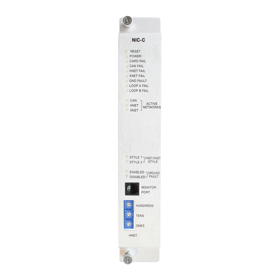
Figure 1
NIC-C Network Interface Card
Siemens
Siemens
Industry
Industry
Industry, , , , , Inc.
Siemens Industry
Siemens
Siemens
Industry
Building
Building
Building
Building T T T T T ec
Building
ec
echnologies Di
ec
ec
hnologies Di
hnologies Di
hnologies Division
hnologies Di
Inc.
Inc.
Inc.
Inc.
vision
vision
vision
vision
Advertisement
Table of Contents

Related Manuals for Siemens NIC-C


Summary of Contents for Siemens NIC-C
- Page 1 XNET network. The connection to HNET is not supported. The CAN network is also supported by NIC-C. It can be isolated within a given enclosure or extended external to the enclosure. External CAN networks require either an RNI, OCM-16 or SIM-16 in the remote enclosure.
-
Page 2: Operation
Individual LEDs are included for HNET/XNET Loop A and Loop B faults, as well as an LED for complete failure of the HNET or XNET network or the CAN network. The NIC-C can also be configured to perform ground fault detection on both net- works. - Page 3 Controls and Indicators The front panel of the NIC-C contains one reset switch, fifteen LEDs, one network port and three HNET address switches as shown in Figure 1. A reset switch is located on the top of the front panel. Pushing the reset switch re- initializes the NIC-C operation.
-
Page 4: Pre-Installation
Move the lever to the up position to disable ground fault detection. (Refer to Figure 2.) It is recommended to enable ground fault detection on ONLY one NIC-C in the system. (One for HNET and if used, one for XNET.) If multiple NIC-Cs have ground fault detection... - Page 5 Figure 3 shows the wiring for each pair. Be sure to connect the pairs following the proper polarity. Do not cross the A and B pairs. Removing the NIC-C from the CC-5 will break the network. Removing power from the NIC-C does not break the network.
- Page 6 <10K ohms on pins 1 - 4. DO NOT USE DO NOT USE DO NOT USE Figure 4 NIC-C Class-B/Style 4 (ULC DCLB) Network Wiring PAIR B NOTES: SUPERVISED POWER LIMITED 1. No EOLR required. 2. 18 AWG min., 12 AWG max.
- Page 7 Siemens Industry, Inc. P/N 315-033240-13 Building Technologies Division...
- Page 8 Siemens Industry, Inc. P/N 315-033240-13 Building Technologies Division...
- Page 9 80 Ohms max. per pair. Positive or negative ground fault detected at Unshielded twisted pair - .5μF line to line <10K ohms on pins 3-4, 7-8 of the NIC-C. Shielded twisted pair - .3μF line to line, .4μF Each pair independently supervised.
- Page 10 120 Ohm CAN termination resistor P/N 140-820150 into TB1 10 and 11 on the PSC-12. The NIC-C may be installed into any open slot of a CC-5. To Connect the External CAN Bus Loosen the screw of the terminal by turning it counterclockwise.
- Page 11 24V 4A FAIL REFER TO SINGLE ENCLOSURE WIRING DIAGRAM FIG. 6 24 V BATTERY INCLUDED IN CAN TERMINATOR KIT N GND (SHIPPED WITH THE NIC-C) Figure 11 CAN Wiring - Single Remote Enclosure SHIELD CLASS-B/ CONNECTION STYLE 4 POINTS LCM-8...
-
Page 12: Installation
The screw terminals can accommodate one 12 -18 AWG or two 16-18 AWG. INSTALLATION The NIC-C plugs perpendicularly into one slot in the CC-5 card-cage via two 96-pin DIN connectors and can occupy any slot in the card cage. (Refer to Figure 14.) -
Page 13: Cyber Security Disclaimer
Cyber security disclaimer Siemens products and solutions provide security functions to ensure the secure operation of building comfort, fire safety, security management and physical security systems. The security functions on these products and solutions are important components of a comprehensive security concept. - Page 14 For CE applications in Cerberus E100 systems refer to Installation Instruction A24205-A334-B844 (English) or A24205-A334-A844 (German). Siemens Industry, Inc. Siemens Canada, Ltd. Siemens AG P/N 315-033240-13 Building Technologies Division 1577 North Service Road East I BT DE FS SYS Document ID A6V10239113...