Toro Groundsmaster 4300-D Operator's Manual
Traction unit
Hide thumbs
Also See for Groundsmaster 4300-D:
- Service manual (399 pages) ,
- Operator's manual (80 pages) ,
- Operator's manual (56 pages)

Related Manuals for Toro Groundsmaster 4300-D


Summary of Contents for Toro Groundsmaster 4300-D
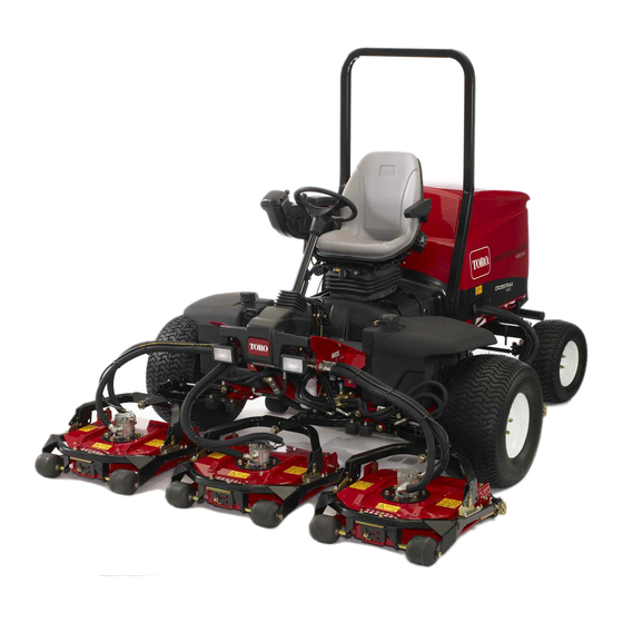
- Page 1 Form No. 3376-508 Rev B Groundsmaster ® 4300-D Traction Unit Model No. 30864—Serial No. 313000001 and Up *3376-508* B Register at www.Toro.com. Original Instructions (EN)
- Page 2 Whenever you need service, genuine Toro parts, or additional information, contact an Authorized Service Dealer or Toro Customer Service and have the model and serial numbers of your product ready. The model © 2017—The Toro® Company Contact us at www.Toro.com.
- Page 3 Safety ............... 4 System............46 Safe Operating Practices........4 Brake Maintenance ..........47 Toro Riding Mower Safety........6 Adjusting the Service Brakes ......47 Sound Power Level ..........6 Adjusting the Parking Brake ......47 Sound Pressure Level ........6 Belt Maintenance ..........
-
Page 4: Safety
Preparation Safety • While mowing, always wear substantial footwear, long trousers, hard hat, safety glasses, and ear Improper use or maintenance by the operator protection. Long hair, loose clothing, or jewelry or owner can result in injury. To reduce the may get tangled in moving parts. -
Page 5: Maintenance And Storage
• – stay alert for humps and hollows and other Do not operate the mower under the influence of hidden hazards; alcohol or drugs. – Do not turn sharply. Use care when reversing. • Lightning can cause severe injury or death. If lightning is seen or thunder is heard in the area, do –... -
Page 6: Toro Riding Mower Safety
The following list contains safety information specific object injuries. Do not resume mowing until the to Toro products or other safety information that you area is cleared. must know that is not included in the CEN, ISO, or ANSI standard. -
Page 7: Vibration Level
Vibration Level Hand-Arm Measured vibration level for right hand = 2.4 m/s Measured vibration level for left hand = 2.1 m/s Uncertainty Value (K) = 1.18 m/s Measured values were determined according to the procedures outlined in EN 836. Whole Body Measured vibration level = 0.9 m/s Uncertainty Value (K) = 0.45 m/s Measured values were determined according to the... -
Page 8: Safety And Instructional Decals
Safety and Instructional Decals Safety decals and instructions are easily visible to the operator and are located near any area of potential danger. Replace any decal that is damaged or lost. decal93-7272 93-7272 decal117-2718 117–2718 1. Cutting/dismemberment hazard; fan—stay away from moving parts. - Page 9 decal93-6681 93-6681 1. Cutting/dismemberment—hazard, fan-stay away from moving parts. decal120-4158 120–4158 1. Read the Operator’s 3. Engine—preheat Manual. 2. Engine—start 4. Engine—stop decal106-6754 106-6754 1. Warning—do not touch the hot surface. decal93-6689 93-6689 2. Cutting/dismemberment hazard, fan and entanglement hazard, belt—stay away from moving parts. 1.
- Page 10 decal125-2927 125–2927 1. Read the Operator’s Manual for maintenance information. decalbatterysymbols Battery Symbols Some or all of these symbols are on your battery 1. Explosion hazard 6. Keep bystanders a safe distance from the battery. 2. No fire, open flame, or 7.
-
Page 11: Setup
Setup Loose Parts Use the chart below to verify that all parts have been shipped. Procedure Description Qty. – No parts required Adjust the tire pressure. – No parts required Adjust the step height. – No parts required Adjust the control arm position. –... -
Page 12: Adjusting The Control Arm Position
g003959 Figure 2 g004152 1. Step 2. Step brackets Figure 3 1. Control arm 3. Bolts (2) Raise or lower the step to the desired height 2. Retaining brackets and re-secure the brackets to the frame with the 2 bolts and nuts. Rotate the control arm to the desired position Repeat the procedure on the other step. -
Page 13: Product Overview
Parking Brake Product Overview To engage the parking brake, (Figure 5) push down on the brake pedal and press the top forward to latch. Controls To release the parking brake, press the brake pedal until the parking brake latch retracts. Seat Adjusting Knobs The seat adjusting lever (Figure... -
Page 14: Key Switch
Hydraulic Filter Restriction Indicator With the engine running at normal operating temperature, view the indicator (Figure 7), it should be in the Green zone. When the indicator is in the Red zone, change the hydraulic filters. g021208 Figure 6 1. Lower mow/raise control 4. - Page 15 Using the InfoCenter LCD Display InfoCenter Icon Description SERVICE DUE Indicates when scheduled service The InfoCenter LCD display shows information should be performed about your machine such as the operating status, various diagnostics and other information about the Engine rpm/status—indicates the engine rpm machine (Figure...
- Page 16 The Faults menu contains a list of the recent machine faults. Refer to the Service Manual Cutting units are lowering or your Toro Distributor for more information on the Faults menu and the information Cutting units are raising contained there.
- Page 17 Units Controls the units used on the InfoCenter. The menu choices If you changed the PIN code and forgot the are English or Metric code, contact your Authorized Toro Distributor for assistance. Language Controls the language used on the InfoCenter*.
-
Page 18: Specifications
Specifications Press the middle button to enter the PIN code (Figure 11D). Note: Specifications and design are subject to Wait until the red indicator light of the InfoCenter change without notice. illuminates. Transport Width 226 cm (89 inches) Note: If the InfoCenter accepts the PIN code and the protected menu is unlocked, the word Width of cut 229 cm (90 inches) -
Page 19: Operation
Operation Note: Determine the left and right sides of the machine from the normal operating position. CAUTION If you leave the key in the ignition switch, someone could accidently start the engine and seriously injure you or other bystanders. Lower the cutting decks to the ground, set the parking brake and remove the key from the ignition switch before servicing or making g021866... - Page 20 Fuel Tank Capacity DANGER Fuel tank capacity: 53 L (14 US gallons) In certain conditions, fuel is extremely flammable and highly explosive. A fire or Fuel Specification explosion from fuel can burn you and others and can damage property. Important: Use only ultra-low sulphur diesel •...
-
Page 21: Checking The Hydraulic-Fluid Level
Use B5 (biodiesel content of 5%) or lesser blends 18.9 L (5 US gallon) pails or 208 L (55 US gallon) drums. in cold weather. See the Parts Catalog or your Toro Distributor for part numbers.) • Monitor seals, hoses, gaskets in contact with fuel as they may be degraded over time. -
Page 22: Check The Torque Of The Wheel Nuts
The engine has ceased running due to lack of fuel. gallons) of hydraulic oil. Order Part Number 44-2500 • Maintenance has been performed upon the fuel from your Toro Distributor. system components. Position machine on a level surface, lower the cutting decks and stop the engine. -
Page 23: Cutting Grass With The Machine
Cutting Grass with the Diesel Particulate Filter Regeneration Machine Note: The diesel particulate filter (DPF) is part of the exhaust Cutting grass at a rate that loads the engine promotes DPF regeneration. system. The diesel-oxidation catalyst of the DPF reduces harmful gasses and the soot filter removes Move the machine to the job site. - Page 24 DPF Soot Accumulation • DPF regeneration is a process that heats the DPF to convert the soot to ash. • Over time, the DPF accumulates soot in the soot • In addition to the warning messages, the computer filter. The computer for the engine monitors the reduces the power produced by the engine at soot level in the DPF.
- Page 25 DPF Ash Accumulation • When enough ash accumulates, the engine computer sends information to the InfoCenter in • The lighter ash is discharged through the exhaust the form of a system advisory or an engine fault to system; the heavier ash collects in the soot filter. indicate the accumulation of ash in the DPF.
- Page 26 Types of Diesel Particulate Filter Regeneration Types of diesel particulate filter regeneration that are performed while the machine is operating: Type of Regeneration Conditions for DPF regeneration DPF description of operation Passive Occurs during normal operation of the machine at The InfoCenter does not display an icon indicating high-engine speed or high-engine load passive regeneration.
- Page 27 DPF is already in need of a parked When the recovery-regeneration icon regeneration displayed in the InfoCenter, a recovery regeneration is requested. Contact your Authorized Toro Distributor to have a service technician perform the recovery regeneration. • A recovery regeneration requires up to 4 hours to complete.
- Page 28 Reset Regeneration Parked Regeneration g214713 g214711 Figure 23 Figure 22 Parked-regeneration request icon Assist/reset-regeneration icon • The parked-regeneration requested icon displays • The assist/reset-regeneration icon displays in the in the InfoCenter (Figure 23). InfoCenter (Figure 22). • If a parked regeneration is needed, the InfoCenter •...
- Page 29 Engage the parking brake. Set the throttle to the low I position. Performing a Parked Regeneration Note: For instructions on unlocking protected menus, refer to Accessing Protected Menus (page 17). Access the protected menu and unlock the protected settings submenu (Figure 25);...
- Page 30 g211986 g212405 Figure 29 Figure 31 Move the throttle control to and press LOW IDLE The “Waiting on ” message displays the center button (Figure 30). (Figure 32). g212372 g212406 Figure 30 Figure 32 The following messages display as the parked The computer determines whether the regeneration process begins: regeneration runs.
- Page 31 The engine is cold—wait. The engine is warm—wait. The engine hot—regeneration in progress (percent complete). The parked regeneration is complete when the “Regen Complete” message displays in the InfoCenter. Press the left button to exit to the home screen (Figure 35).
-
Page 32: Pushing Or Towing The Machine
(Figure 38). • You need a distributor technician to perform the recovery regeneration process; contact your Authorized Toro Distributor. Pushing or Towing the Machine In an emergency, the machine can be moved by actuating the bypass valve in the variable displacement hydraulic pump and pushing or towing the machine. -
Page 33: Understanding The Diagnostic Light
Understanding the Diagnostic Light The machine is equipped with a diagnostic light which indicates if the machine detects a malfunction. The diagnostic light is located on the InfoCenter, above the display screen (Figure 41). When the machine is functioning properly and the key switch is moved to the On/Run position, the diagnostic light will turn on briefly to indicate the light is working properly. -
Page 34: Checking The Interlock Switches
Checking the Interlock Locate the appropriate output function in the diagnostics menu on the InfoCenter. Switches Sit on the seat and attempt to operate the desired function of the machine. The appropriate The purpose of the interlock switches is to prevent the outputs should change state to indicate that the engine from cranking or starting unless the traction ECM is turning on that function. - Page 35 Note: Allow the engine to idle for 5 minutes before shutting it off after a full load operation. Failure to do so may lead to turbo-charger trouble. Mow when the Grass is Dry Mow either in the late morning to avoid the dew, which causes grass clumping, or in late afternoon to avoid the damage that can be caused by direct sunlight on the sensitive, freshly mowed grass.
-
Page 36: Maintenance
Maintenance Note: Determine the left and right sides of the machine from the normal operating position. Recommended Maintenance Schedule(s) Maintenance Service Maintenance Procedure Interval • Torque the wheel lug nuts to 94 to 122 N-m (70 to 90 ft-lb). After the first hour •... -
Page 37: Daily Maintenance Checklist
Daily Maintenance Checklist Duplicate this page for routine use. For the week of: Maintenance Check Item Mon. Tues. Wed. Thurs. Fri. Sat. Sun. Check the safety interlock operation. Check the brake operation. Check the engine oil and fuel level. Drain the water/fuel separator. Check the air filter restriction indicator. -
Page 38: Service Interval Chart
Service Interval Chart decal125-2927 Figure 42 CAUTION If you leave the key in the ignition switch, someone could accidently start the engine and seriously injure you or other bystanders. Remove the key from the ignition before you do any maintenance. Lubrication Greasing the Bearings and Bushings... - Page 39 • Cutting unit lift arm cylinders (2 each) (Figure g011612 Figure 44 • Lift arm pivots (1 each) (Figure • Cutting unit carrier frame pivot (1 each) (Figure g003987 Figure 47 • Axle steering pivot (1) (Figure g011613 Figure 45 g004169 Figure 48 •...
-
Page 40: Engine Maintenance
Engine Maintenance • Brake pedal (1) (Figure Servicing the Air Cleaner Check the air cleaner body for damage which could cause an air leak. Replace if damaged. Check the whole intake system for leaks, damage or loose hose clamps. g011615 Figure 50 Service the air cleaner filter only when the service indicator... -
Page 41: Servicing The Engine Oil
Alternate oil: SAE 10W-30 or 5W-30 (all temperatures) g020435 Figure 55 Toro Premium Engine Oil is available from your 1. Dipstick 2. Oil fill cap Authorized Toro Distributor in either 15W-40 or 10W-30 viscosity grades. See the parts catalog for part numbers. -
Page 42: Servicing The Diesel-Oxidation Catalyst Doc) And The Soot Filter
Manual for information on disassembling and assembling the diesel-oxidation catalyst and the soot filter of the DPF. Refer to your Authorized Toro Distributor for diesel-oxidation catalyst and the soot filter replacement parts or service. Contact your Authorized Toro Distributor to have them reset the engine ECU after you install a clean DPF. -
Page 43: Fuel System Maintenance
Fuel System Maintenance DANGER Under certain conditions, diesel fuel and fuel vapors are highly flammable and explosive. A fire or explosion from fuel can burn you and others and can cause property damage. • Use a funnel and fill the fuel tank outdoors, g007367 in an open area, when the engine is off and Figure 59... -
Page 44: Fuel Pick-Up Tube Screen
Electrical System Remove the filter and clean the filter head mounting surface (Figure 60). Maintenance Lubricate the filter gasket with clean lubricating engine oil. Refer to the Engine Operator's Important: Before welding on the machine, Manual, included with the machine, for additional disconnect both cables from the battery, both wire information. -
Page 45: Fuses
Fuses Drive System Maintenance There are 8 fuses in the electrical system. The fuse block (Figure 61) is located behind the control arm access panel. Adjusting the Traction Drive for Neutral The machine must not creep when the traction pedal is released. -
Page 46: Adjusting The Rear Wheel Toe-In
Cooling System Stop the engine. Remove the jack stands and lower the machine to the shop floor. Maintenance Test drive the machine to make sure it does not creep. Removing Debris from the Adjusting the Rear Wheel Cooling System Toe-in Remove debris from the screen and radiator/oil cooler Rotate the steering wheel so that the rear daily (clean more frequently in dirty conditions). -
Page 47: Brake Maintenance
Brake Maintenance Adjusting the Service Brakes Adjust the service brakes when there is more than 2.5 cm (1 inch) of free travel of the brake pedal, or when the brakes do not work effectively. Free travel is the distance the brake pedal moves before you feel braking resistance. -
Page 48: Belt Maintenance
Belt Maintenance Servicing the Alternator Belt Service Interval: After the first 10 hours Every 100 hours Check the condition and tension of the belt (Figure 69) after every 100 operating hours. Proper tension will allow 10 mm (3/8 inch) deflection when a force of 44 N (10 lb) is applied on the belt midway between the pulleys. -
Page 49: Hydraulic System Maintenance
Filters Change hydraulic fluid after every 800 operating hours, in normal conditions. If fluid becomes The hydraulic system is equipped with a service contaminated, contact your local Toro distributor interval indicator (Figure 71). With the engine running, because the system must be flushed. Contaminated view the indicator, it should be in the Green zone. -
Page 50: Checking The Hydraulic Lines And Hoses
Figure 73 Use the hydraulic system test ports to test the 1. Hydraulic filter pressure in the hydraulic circuits. Contact your local Toro distributor for assistance. Remove the filter. Lubricate the gasket on the new filter with hydraulic oil. Ensure that the filter mounting area is clean. -
Page 51: Storage
Clean the battery, terminals, and posts with a wire brush and baking soda solution. Coat the cable terminals and battery posts with Grafo 112X skin-over grease (Toro Part No. 505-47) or petroleum jelly to prevent corrosion. Slowly recharge the battery every 60 days for 24 hours to prevent lead sulfation of the battery. -
Page 52: Schematics
Schematics g011593 Hydraulic Schematic (Rev. A) - Page 53 Notes:...
- Page 54 Notes:...
- Page 55 Notes:...
-
Page 56: The Toro Total Coverage Guarantee
Countries Other than the United States or Canada Customers who have purchased Toro products exported from the United States or Canada should contact their Toro Distributor (Dealer) to obtain guarantee policies for your country, province, or state. If for any reason you are dissatisfied with your Distributor's service or have difficulty obtaining guarantee information, contact the Toro importer.