Table of Contents
Advertisement
・This product is for industrial
equipment. Don't use this
product at general household.
If you are the first user of this product, please be sure to purchase and read
the optional Engineering Material (DV0P4210), or downloaded Instruction
Manual from our Web Site.
[Web address of Motor Company, Matsushita Electric Industrial Co., Ltd.]
http://industrial.panasonic.com/ww/i_e/25000/motor_fa_e/motor_fa_e.html
<Contents>
1. Introduction ................................. B2
On Opening the Package ............................... B2
Check of the Driver Model .............................. B2
Check of the Motor Model .............................. B3
2. Installation .................................. B4
Driver .............................................................. B4
Motor .............................................................. B6
Console .......................................................... B8
(Connection to Encoder) .............................. B22
Technical reference
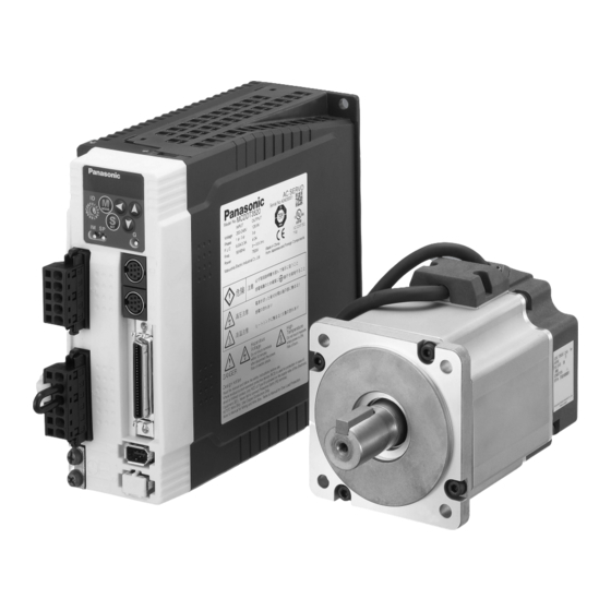
AC Servo Motor & Driver
MINAS A4-series
•
Thank you very much for your
purchase of Panasonic AC Servo
Motor & Driver, MINAS A4-series.
•
Before use, refer this technical
reference and safety instructions
to ensure proper use. Keep this
technical reference and read
when necessary.
•
Make sure to forward this technical
reference for safety to the final
user.
page
4. Parameter .................................. B27
Outline of Parameter .................................... B27
How to Set .................................................... B27
Setup with the Front Panel ........................... B27
®
.......................................................
Setup with the Console ................................ B28
How to Connect ............................................ B29
Composition and List of Parameters ............ B30
5. Protective Functions ................ B36
Composition of Peripheral Equipments ........ B41
Conformity to UL Standards ......................... B44
8. Built-in Holding Brake ............. B45
9. Dynamic Brake ......................... B47
After-Sale Service (Repair) .......... B51
page
IMC54D
Z0404-6066
Advertisement
Table of Contents

Related Manuals for Panasonic MINAS A4-series


Summary of Contents for Panasonic MINAS A4-series
-
Page 1: Table Of Contents
product at general household. MINAS A4-series • Thank you very much for your purchase of Panasonic AC Servo Motor & Driver, MINAS A4-series. • Before use, refer this technical reference and safety instructions to ensure proper use. Keep this technical reference and read when necessary. -
Page 2: Introduction
1. Introduction On Opening the Product Package Check of the Motor Model • Make sure that the model is what you have ordered. Contents of Name Plate • Check if the product is damaged or not during transportation. Serial Number Model CONT. -
Page 3: Installation
2. Installation Install the driver and the motor properly to avoid a breakdown or an accident. E and F-frame Driver Mounting bracket Installation Place 1) Indoors, where the products are not subjected to rain or direct sun beams. The prod- ucts are not waterproof. -
Page 4: Motor
2. Installation Motor Oil/Water Protection 1) Don't submerge the motor cable to water or oil. Motor Installation Place Cable 2) Install the motor with the cable outlet facing downward. Since the conditions of location affect a lot to the motor life, select a place which meets 3) Avoid a place where the motor is subjected to oil or water. -
Page 5: Console
2. Installation Console How to Connect Installation Place 1) Indoors, where the products are not subjected to rain or direct sun beam. The prod- ucts are not waterproof. 2) Where the products are not subjected to corrosive atmospheres such as hydrogen Connect to CN X4. -
Page 6: System Configuration And Wiring
3. System Configuration and Wiring Overall Wiring (Connecting Example of C-frame, 3-phase) • Wiring of the Main Circuit PC (to be supplied by customer) Circuit Breaker (NFB) Use the circuit breaker matching capacity of the power source to Setup support software protect the power lines. -
Page 7: Overall Wiring (Connecting Example Of E-Frame)
3. System Configuration and Wiring Overall Wiring (Connecting Example of E-frame) • Wiring of the Main Circuit PC (to be supplied by customer) Circuit Breaker (NFB) Use the circuit breaker matching Setup support software capacity of the power source to "PANATERM ®... -
Page 8: Driver And List Of Applicable Peripheral Equipments
3. System Configuration and Wiring Required Circuit Noise Cable Cable Applicable Rated Noise Surge Magnetic Driver and List of Applicable Peripheral Equipments Power breaker Driver Voltage filter for diameter diameter Connection (at the rated (rated motor output filter absorber contactor signal (main circuit) (control circuit) -
Page 9: Wiring Of The Main Circuit (A To D-Frame)
3. System Configuration and Wiring Wiring of the Main Circuit (A to D-frame) Wiring of the Main Circuit (E and F-frame) • Wiring should be performed by a specialist or an authorized personnel. • Wiring should be performed by a specialist or an authorized personnel. •... -
Page 10: Wiring Method To Connector (A To D-Frame)
3. System Configuration and Wiring Wiring method to connector (A to D-frame) Wiring Diagram Compose the circuit so that the main circuit power will be shut off when an error occurs. • Follow the procedures below for the wiring connection to the Connector CN X1 and X2 . In Case of Single Phase, 100V (A and B-frame) How to connect 8 to 9mm... - Page 11 3. System Configuration and Wiring In Case of Single Phase, 200V (C and D-frame) * When you use motor model of In Case of 3-Phase, 200V (E and F-frame) [Motor portion] MSMA, MDMA, MFMA, MHMA Connector : by Japan Aviation Electronics Ind. +10% +10% +10%...
-
Page 12: Wiring To The Connector, Cn X6
3. System Configuration and Wiring Wiring to the Connector, CN X6 (Connection to Encoder) Wiring Diagram In case of 17-bit absolute/incremental encoder Wiring Diagram In case of 2500P/r incremental encoder MSMD 50W to 750W MAMA 100W to 750W MSMD 50W to 750W MQMA 100W to 400W MAMA 100W to 750W CN X6... -
Page 13: Wiring For Typical Control Modes To The Connector Cn X5
3. System Configuration and Wiring Wiring for Typical Control Modes to the Connector CN X5 Wiring Example of Velocity Control Mode Wiring Example of Position Control Mode – B24 – – B25 –... -
Page 14: Parameter
3. System Configuration and Wiring 4. Parameter Outline of Parameter Wiring Example of Torque Control Mode This driver is equipped with various parameters to set up its characteristics and func- tions. This section describes the function and purpose of each parameter. Read and comprehend very well so that you can adjust this diver in optimum condition for your running requirements. -
Page 15: Outline Of Panaterm
4. Parameter Outline of PANATERM ® How to Connect With the PANATERM ® , you can execute the followings. RS232 connection cable (option) 1) Setup and storage of parameters, and writing to the memory (EEPROM). DV0P1960 (for DOS/V machines) 2) Monitoring of I/O and pulse input and load factor. 3) Display of the present alarm and reference of the error history. -
Page 16: Composition And List Of Parameters
4. Parameter Composition and List of Parameters Parameters for Functional Selection Parameter Related control Parameter No. Set up of parameter Range Default Unit mode Group Outline Address of axis 0 to 15 – Functional selection 00 to 0F You can select a control mode, designate I/O Initial display of LED 0 to 17 –... - Page 17 4. Parameter Parameters for Adjustment of Time Constant for Gains and Filters Parameters for Adjustment (2nd Gain Switching Function) Parameter Parameter Default Related control Related control Set up of parameter Range Unit Set up of parameter Range Default Unit A to D to mode mode...
- Page 18 4. Parameter Parameter Related control Parameters for Sequence Set up of parameter Range Default Unit mode Parameter 1st numerator of electronic gear 0 to 10000 – P, F Related control Set up of parameter Range Default Unit mode 2nd numerator of electronic gear 0 to 10000 –...
-
Page 19: Protective Functions
5. Protective Functions Protective Function (What Is Error Code ?) Error Error code Protective function code Protective function • Various protective functions are equipped in the driver. When these are triggered, the Control power supply under- voltage Analog input excess protection motor will stall due to error, the driver will turn the Servo-Alarm output (ALM) to off protection (open). -
Page 20: Maintenance And Inspections . B38
6. Maintenance and Inspections • Routine maintenance and inspection of the driver and motor are essential for the Guideline for Parts Replacement proper and safe operation. Use the table below for a reference. Parts replacement cycle varies depending on the Notes on Maintenance and Inspection actual operating conditions. -
Page 21: Conformity To Ec Directives And Ul Standards
7. Conformity to EC Directives and UL Standards Composition of Peripheral Equipments EC Directives The EC Directives apply to all such electronic products as those having specific func- Installation Environment tions and have been exported to EU and directly sold to general consumers. Those Use the servo driver in the environment of Pollution Degree 1 or 2 prescribed in IEC- products are required to conform to the EU unified standards and to furnish the CE marking on the products. - Page 22 7. Conformity to EC Directives and UL Standards Noise Filter Surge Absorber When you install one noise filter at the power supply for multi-axes application, contact Provide a surge absorber for the primary side of noise filter. to a manufacture of the noise filter. <Remarks>...
-
Page 23: Conformity To Ul Standards
7. Conformity to EC Directives and UL Standards 8. Built-in Holding Brake Noise Filter for Signal Lines * In the applications where the motor drives the vertical axis, this brake would be used to hold and prevent the work (moving load) from falling by gravity while the power to the Install noise filters for signal lines to all cables (power cable, motor cable, encoder cable servo is shut off. -
Page 24: Dynamic Brake
8. Built-in Holding Brake 9. Dynamic Brake Static Rotor Exciting Engaging Releasing Permissible Permissible This driver is equipped with a dynamic brake for emergency stop. Motor Motor Releasing friction inertia current time time work (J) per total work torque x 10 –4 DC A series... -
Page 25: Check Of The Combination Of The Driver And The Motor
10. Check of the Combination of the Driver and the Motor This drive is designed to be used in a combination with the motor which are specified by us. Applicable motor Applicable driver Power Check the series name of the motor, rated output torque, voltage specifications and Motor Rated Rated... -
Page 26: After-Sale Service (Repair)
10. Check of the Combination of the Driver and the Motor After-Sale Service (Repair) Applicable motor Applicable driver Repair Power Motor Rated Rated supply Model Model Frame series rotational speed output Consult to a dealer from whom you have purchased the product for details of repair. Single/3-phase, MDMA102S1* 1.0kW...