
Related Manuals for Panasonic MSDA043A1A


Summary of Contents for Panasonic MSDA043A1A
- Page 1 (217) 352-9330 | Click HERE Find the Panasonic MSDA043A1A at our website:...
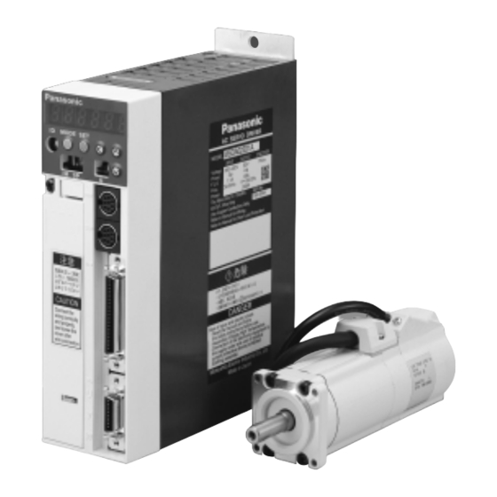
- Page 2 AC Servo Motor Driver MINAS A-series Operating Manual Be sure give this instruction manual to the user. ● Thank you very much for your buying Panasonic AC Servo Motor Driver, A-series. ● Before use, read through this manual to ensure proper use. Keep this manual at an easily accessible place so as Artisan Technology Group - Quality Instrumentation ... Guaranteed | (888) 88-SOURCE | www.artisantg.com...
-
Page 3: Table Of Contents
Table of Contents Safety Precautions ・・・ 4 Before Use Introduction ・・・・・・・・・ 8 ● After Opening the Package ・・・ 8 ● Check the Model of Driver ・・・・ 8 ● Check the Model of Motor ・・・・ 9 ● Check the Combination of Driver and Motor ・・・・・ 10 System Configuration and Wiring ・・・ 18 Preparations ● System Configuration and Wiring ・・・ 18 ● General Wiring Diagram List of Available Components ・・ 20 Adjustments ●... - Page 4 Parts Description ・・・ 12 Installation ・・・・・・・・ 14 ● Driver ・・・・・・・・・・・・・・・・・・・・・・・・ 12 ● Driver ・・・・・・・・・・・・・・・・・・・・・・・・ 14 ● Motor ・・・・・・・・・・・・・・・・・・・・・・・・・ 13 ● Motor ・・・・・・・・・・・・・・・・・・・・・・・・・ 16 Parameter Setting ・・・ 42 Adjustments ・・・・・・ 55 ● Overview ・・・・・・・・・・・・・・・・・・・・・ 42 ● Purposes of Gain Adjustments ・・・・55 ● Parameter Groups and Listing ・・・・ 42 ● Kinds of Gain Adjustments ・・・ 55 ●...
-
Page 5: Safety Precautions
Safety Precautions (Important) Observe the following precautions in order to avoid injuries of opera- tors and other persons, and mechanical damages. ■The following DANGER and CAUTION symbols are used according to the level of dangers possibly occurring if you fail to observe the instructions or precautions indicated. Indicates a potentially hazardous situation which, if not DANGER avoided, will result in death or serious injury. Indicates a potentially hazardous situation which, if not avoided, CAUTION will result in minor or moderate injury and physical damage. ■The following symbols indicate what you are not allowed to do, or what you must observe. This symbol indicates that the operation is pro- hibited. This symbol indicates that the operation must be performed without fail. DANGER An over-current protection, Don't insert your hands in earth leakage breaker, over- the driver. temperature protection and emergency stop should be installed. Failure to observe this Failure to observe this instruction could result in instruction could result in electric shocks, injuries burns and/or electric and/or fire. shocks. − 4 − Artisan Technology Group - Quality Instrumentation ... Guaranteed | (888) 88-SOURCE | www.artisantg.com... - Page 6 DANGER Don't touch the rotating Don't subject the product to part of the motor in motion. water splash, corrosive gases, flammable gases and combustible things. Failure to observe this instruction could Rotating part result in fire. Failure to observe this instruction could result in injuries. Perform the transportation, Do not expose the cables to sharp edges, excessive wiring and inspection at pressing forces, heavy least 10 minutes after the loads or pinching forces. power off. Failure to observe this instruction could result Failure to observe this in electric shocks, instruction could result malfunction and/or in electric shocks. damages.
- Page 7 Safety Precautions (Important) Caution Use the motor and Execute the trialoperations driver in the specified with the motor fixed but combination. without motor load connected. Connecting a load to the motor is possible only after successful trial operation. Failure to observe this Failure to observe this instruction could result instruction could result in injuries. in fire. If an error occurs, Don't touch the motor, remove the causes for driver or its the errora and secure regenerative discharge resistor, since they the safety before restarting the operation. become hot. Failure to observe Failure to observe this instruction could this instruction could result in burns. result in injuries. Avoid extreme Don't modify, dismantle adjustment or change.
- Page 8 Caution Don't hold the cables or After recovery from the motor shaft when power failure, the equipment may restart transpoting the motor. suddenly. Don't approach to the equipment during power failure. Failure to observe this instruction could result in *Provide appropriate settings as a preparedness injuries. against the accidental restart of the machine in order to ensure the safety of personnel. Don't block the heat Observe the voltage dissipation hole or insert specified. foreign matters in it. Failure to observe this Failure to observe this instruction instruction could result could result in in electric shocks, electric shocks, injuries and/or fire. injuries and/or fire. Make sure that the This equipment should be wirings are made treated as an industrial correctly. waste when it is disposed of. When discarding batteries, insulate them with tapes Failure to observe or other similar means and this instruction could obey the local rules.
-
Page 9: Introduction
Introduction After Opening the Package ・ After Opening the Package ・ Make sure that the product is what you have ordered. Check whether the product has been damaged or not during transportation. If the product is not correct, or it has been damaged, contact dealer or sales agent. Check the Model of Driver Name plate AC SERVO DRIVER Number of pulses of the MSDA3A1D1A01 MODEL encoder(resolution) Model INPUT OUTPUT ENCODER Voltage 100-115V 17bits Rated output current Phase 1ø 3ø F.L.C 1.0A 1.0A Rated input voltage Freq. 50/60Hz 0~333.3Hz Power 60/75Åé Wire Only SER.NO. 98120001 Use Copper Conductors Only Refer to Manual for Wiring and Wire Size... -
Page 10: Check The Model Of Motor
Check the Model of Motor Name plate Type CONT. TORQUE 0.64 Nm Rated output AC SERVO MOTOR RATING MODEL MSMA022A1A INS. CLASS B (TÜV) A (UL) Serial No INPUT 3ØAC IP65 Revolution rating CONNECTION RATED OUTPUT SER No. T98120001 RATED FREQ. RATED REV. 3000 r/min MatsushitaElectric Industrial Co..Ltd. Made in Japan Model Designation M S M A 0 4 2 A 1 A... -
Page 11: Check The Combination Of Driver And Motor
MSDA3A3A1A Type1 MSMA3AZA ** 3000r/min 2500P/r, inertia MSDA5A3A1A MSMA5AZA ** 11 wires MSDA013A1A MSMA012A ** 100W 200V MSDA023A1A MSMA022A ** 200W MSDA043A1A Type2 MSMA042A ** 400W MSDA083A1A Type2 MSMA082A ** 750W MSDA103A1A Type4-2 MSMA102A ** 1.0kW MSMA MSDA153A1A MSMA152A ** 1.5kW... - Page 12 With the absolute/incremental type encoder, 17 bits Motor Driver Driver Output Revolution Encoder Series type Voltage Motor type rating rating type symbol MSDA3A1D1A Type1 MSMA3AZC ** MSMA MSDA5A1D1A (Small) MSMA5AZC ** MSDA011D1A MSMA011C ** 100V 100W MSDA021D1A Type2 MSMA021C ** 200W With the MSDA041D1A Type3 MSMA041C ** 400W absolute/ MSDA3A3D1A Type1...
- Page 13 Parts Description Driver [Terminal block cover opened] [Terminal block cover closed] Mounting bracket SET LED indicator button (6 digits) MODE Rotary switch (ID) Data setting MODE MODE selector switch buttons Check pins : SHIFT Cover Terminal : UP securing screw : DOWN Mains power Communication connection connector 1 (CN NET) Communication 注意 Control power connector 2 配線は正しく確実 connection に行い、配線後は (CN SER) 必ずカバーをネジ Controller 止めしてください connection CAUTION (CN I/F) External regenerative...
- Page 14 Motor Encoder cable Motor cable Encoder Brake cable Frame Mounting bolt holes (4) Flange Example: Small Low-Inertia Motor (MSMA Series, 750W and below) < Note > For detailed information for each of motor types, see the drawings in the Appendix. − 13 − Artisan Technology Group - Quality Instrumentation ... Guaranteed | (888) 88-SOURCE | www.artisantg.com...
- Page 15 Installation The driver and motor should be properly installed to avoid failures, mechanical damages and injuries. Driver Location A Indoors, where the driver is not subjected to rain water and direct sun beams. Note that the driver is not a waterproof structure. B A void the place where the driver is subjected to corrosive gases, flammable gases, grinding liquids, oil mists, iron powders and cutting particles. C Place in a well-ventilated, and humid- and dust-free space. D Place in a vibration-free space. Environmental Conditions Item Conditions Ambient temperature 0 to 55°C (free from freezing) Ambient humidity Not greater than 90%RH (free from condensation) Storage temperature -20 to 80°C (free from condensation) Storage humidity Not greater than 90%RH (free from condensation) Vibration Not greater than 5.9m/s2 (0.6G) at 10 to 60 Hz Altitude Not greater than 1000 m How to Install A his is a rack-mount type. Place the driver vertically. Allow enough space surrounding for ventilation. Type 3 and smaller (up to 750W): Back panel mount type (projected, use Bracket A) Type 4 and larger (1kW and larger): Front panel mount type (recessed, use Bracket B) (Types 1 to 3) (Types 4-2 〜 4-3,Type 5) Bracket A Bracket B MSDA 750W MSDA 1kW...
- Page 16 Mounting Direction and Space Requirements ・ Allow enough space to ensure enough cooling. ・ Install fans to provide a uniform distribution of temperature in the control box. ・ Observe the environmental requirements for the control box, mentioned in the previous page. min. 100mm MODE MODE MODE MODE min. min. min. min. min. 40mm 10mm 10mm 10mm 40mm min. 100mm < Notes > Conformance to UL Standard Observing the following instruction makes this driver a UL508C standard authorized and EN50178 approved product. 1 Instructions in wiring (1)Use copper conductor wire with the rated temperature of 60℃ or higher for wiring to terminal blocks or grounding terminals.
- Page 17 Installation Motor Location A Indoors, where the driver is not subjected to rain water and direct sun beams. B Avoid the place where the driver is subjected to corrosive gases, flammable gases, grinding liquids, oil mists, iron powders and cutting particles. C Place in a well-ventilated, and humid- and dust-free space. D Easy maintenance, inspections and cleaning is also important. Environmental Conditions Item Conditions Ambient temperature 0 to 40°C (free from freezing) Ambient humidity Not greater than 90%RH (free from condensation) Storage temperature -20 to 80°C (free from condensation) Storage humidity Not greater than 90%RH (free from condensation) Vibration Not greater than 49m/s2 (5G) in operation; not greater than 24.5m/s2 (2.5G) at rest How to Install The motor can be installed either vertically or horizontally. Observe the following notes. A Horizontal mounting ・Place the motor with the cable outlet facing down to prevent the entry of oil and water. B Vertical mounting ・ If the motor is coupled with a reduction gear, make sure that the oil in the reduction gear does not enter into the motor. Oil and Water Protections A This motor(IP65 rating) can be used where it is subjected to water and/or oil drops, but is not water or oilproof. Therefore, the motors should not be placed or used in such environment. B If the motor is coupled with a reduction gear, use the motor should with oil seals to prevent the reduction gear oil from entering into the motor.
- Page 18 Cable: Stress Relieving A Make sure that the cables are not subjected to moments or vertical loads due to external bending forces or self-weight at the cable outlets or connections. B In case the motor is movable, secure the cable (proper one supplied together with the motor) to a stationery part (e.g. floor), and it should be extended with an additional cable which should be housed in a cable bearer so that bending stresses can be minimized. C Make the bending radius of cables as large as possible. Permissible Shaft Load A Make sure that both of radial and thrust load to be applied to the motor shaft during installation and running, becomes within the specified value of each model. B Pay extra attention at installing a rigid coupling(especially an excess bending load which may cause the damages and/or wear of the shaft and bearings. C Flexible coupling is recommended in order to keep the radial load smaller than the permissible value, which is designed exclusively for servo motors with high mechanical stiffness. D For the permissible shaft load, see "Allowable Shaft Loads Listing" in Appendix. Installation Notes A Don't hit the shaft with a hammer directly while attaching/detaching the coupling to the motor shaft.(otherwise the encoder at the opposite end of the shaft will be damaged). B Try perfect alignment between shafts (misalignment may cause vibration, and damages of the bearings). − 17 − Artisan Technology Group - Quality Instrumentation ... Guaranteed | (888) 88-SOURCE | www.artisantg.com...
-
Page 19: System Configuration And Wiring
System Configuration and Wiring General Wiring Diagram ■ Main Circuits Non-Fuse Breaker (NFB) Used to protect the power lines: overcurrent will shutoff the circuit. Noise Filter (NF) Prevents the external noise from the power line, and reduces the effect of the noises generated by the servo motor. Magnetic Contactor (MC) Turns on/off the main power of the servo motor. Used together with a surge absorber. Reactor (L) Reduces the harmonic in the main power. Motor cable: ・ Without a brake ・ With a brake Terminals P, B1 and B2 ・ N o r m a l l y k e e p B 1 a n d B 2 shorted. - Page 20 Personal computer Communication control software PENATERM ■ CN SER/CN NET (to connect a PC or controller) ■ CN I/F (to connect a controller) ■ CN SIG (to connect an encoder) Encoder cable Motor cable Brake power supply (24VDC) − 19 − Artisan Technology Group - Quality Instrumentation ... Guaranteed | (888) 88-SOURCE | www.artisantg.com...
-
Page 21: List Of Available Components
System Configuration and Wiring List of Available Components Driver Non-fuse Terminals Mai n c i r cui t w i r e d i a meter Required Power Noise Magnetic contactor Control powerwire breaker (L1, L2, L3, U, on the Series Voltage Output (at the rated load) filter (contacts) diameter (r and t) (rated current) V, W and E) termi n al b l o ck MSDA 30〜50W approx. 0.3kVA... - Page 22 Driver Non-fuse Mai n c i r cui t w i r e d i a meter Terminals Required Power N o i s e Magnetic contactor ontrol powerwi r e di- breaker (L1, L2, L3, U, on the Series Voltage Output (at the rated load) f i l t e r (contacts) ameter (r and t) (rated current)
-
Page 23: Main Circuits
System Configuration and Wiring Main Circuits Don't turn on the main power until the wiring is completed, to avoid electric shocks. Wiring Instructions A Detach the terminal block by removing the cover securing screw. B Make necessary connections. Use clamp terminal connectors with an insulation cover. For wire diameter and connector sizes, see List of Available Components (page 20). C Attach the terminal block cover and tighten the cover securing screw. See the nameplate of the driver to check the power specification. Install a non-fuse breaker or leakage breaker. The latter should be a special one intended for inverters, i.e. with a countermeasure against higher harmonics. Install a noise filter without fail. Install a surge absorber to the magnetic contactor coil. Install an AC reactor. Power supply For single-phase 100V, connect between L1 and r, and between L3 and t. Do not use L2 terminal. Don't remove the short bar connecting between B1 and B2. Remove this only when an external regenerative discharge resistor is connected. Ensure matching in color between the motor wires and terminals (U, V and W). Don't short circuit or ground. Don't connect to the Yellow 2 wires main power. If cannon plugs are used, see the next page. White or yellow Black Connect to the grounding system of the facility. Green Never fail to connect between the driver's protective yellow earth terminal ( ) and control board's protective earth terminal (PE) in order to avoid electric shocks. - Page 24 Wiring Diagrams For 3-phase 200VAC For 1-phase 100V Single-phase For 3-phase 100V 200V DC/DC DC/DC 172167-1 172159-1 172167-1 172159-1 (Nihon AMP) (Nihon AMP) (Nihon AMP) (Nihon AMP) White or yellow White or yellow Black Black Green/yellow Green/yellow ALMo ALMo Motor モータ ALMp ALMp 12~24V 12~24V COMp COMp CN / I F CN / I F ●...
-
Page 25: Cn Sig Connector
System configutration and wiring CN SIG Connector (For Encoder) Wiring Instructions The cable length between the driver and mo- tor should be max. 20 m. If you use a longer cable, contact the dealer or sales agent. Power MODE Separate these wiring min. 30 cm from the main circuit wires. Don't lay these wires in Motor Encoder the same duct of the mains or bundle with min. 30 cm them. max. 20 cm Two types of encoder wire exit: One Connector Connecting cable is "Lead wire + connector" and other is Cannon plug type(depending on the motor model). max. 20 cm When you prepare your own connecting cables see the "Optional Parts" for Connecting cable Cannon plug connectors, and ① Follow the wiring diagram and use the ② Wire material: 0.18 mm2 (AWG24) or above, shielded twist-paired wire max. 20 cm with an enough bending durability, 3.6V+ BATT+ 3.6VG BATT- ③Signal/power paired wires should be... -
Page 26: For Encoder
Wiring Diagrams (with a 2500P/r incremental type encoder ([A]*1)) ● MSMA 750W or smaller, and MQMA 172171-1 172163-1 (日本AMP製) (日本AMP製) CN SiG 黄 橙 黄/緑 青 赤 桃 紫 水 エンコーダ電源 白 黒 モータ側 中継ケーブル ドライバ側 ● MSMA 1kW or larger, MDMA, MFMA, MHMA and MGMA MS3102A20-29P MS3106B20-29S (日本航空電子製) (日本航空電子製) CN SiG キャノンプラグ エンコーダ電源 モータ側 中継ケーブル ドライバ側 * 1 For encoder symbols, see Table 1-b in page 9. ) shows a pair of twisted wires. - Page 27 System configutration and wiring Wiring Diagram Driver with a 17 bits absolute encoder ([C]*1) ( ) Driver with a 17 bits absolute/incremental encoder ([D]*1) ● MSMA 750W or smaller, and MQMA 172161-1 172169-1 *2 (日本AMP製) CN SiG (日本AMP製) 赤 3.6V+ BATT+ 桃 BATT- 3.6VG 水色 RX/TX 紫 RX/TX 白 エンコーダ電源 黒 黄/緑 モータ側 中継ケーブル ドライバ側 ● MSMA 1kW or larger、MDMA、MFMA、MHMA、MGMA MS3102A20-29P MS3106B20-29S *2 (日本航空電子製) (日本航空電子製) CN SiG キャノンプラグ...
-
Page 28: Cn Ser And
CN SER and CN NET Connectors (For PC or Controller) ・ These connectors can be used as either RS232C or RS485. There are three ways for using these connectors as shown below. For RS232C communication only Connect the personal computer and the driver 1:1 through RS-232C,The PANATERM using for communication control softwere. The PANATERM using this function the monitor of the personal computre settings wave graphics. Turn off the power of both the How to connect driver and computer, before Special connecting or disconnecting cable (optional) MODE the connectors. Tighten the screws firmly. CN SER RS232C connector ロータリスイッチ(ID)は1(出荷設定)でご使用ください。 (rear) For both RS232C and RS485 communication You connect the host and the 1st driver with RS232C, and connect the drivers in series with RS485. RS485 RS485 Host (personal computer or controller) MODE MODE MODE RS232C 232C/485 connector RS485 connector... -
Page 29: Cn I/F Connector (For Controller
List of Available Components CN I/F Connector (For Controller) Wiring Instructions Displace the peripheral devices such as 3m以内 the controller max. 3 m away from the 制御 driver. MODE 装置 Separate these wiring min. 30 cm from 30cm以上 the main circuit wires. Don't lay these 電源部 wires in the same duct of the モータ mains or bundle with them. The control power (VDC) between COM+ and COM- should be supplied by the customer (recommended voltage: +12VDC to +24VDC). COM+ Control signal output terminals can accept max. 24V or 50mA: Don't apply larger voltage or current exceeding these limits. If you directly activate a relay using the control signal, install a diode in parallel to the relay as アナログ shown in the left figure. Without a diode or with it but placed in the opposite direction, the driver COM- will be damaged. Use a shielded twist-paired type for the CN I/F wiring of pulse input, encoder signal output or analog command input. The Frame Ground (FG) is connected to an earth terminal in the driver. ● CN I/F Connector Specifications Connector to controller side Receptacle on the Manufacturer... -
Page 30: Circuits Available For Typical Control Modes
I F オープンコレクタ COM+ の場合 40ページ PI 参照 指令パルス入力禁止入力 4.7K カウンタクリア入力 PULS1 サーボオン入力 SRV-ON PULS2 指令パルス P動作/第2ゲイン切替入力 入力 SIGN1 GAIN 指令分周逓倍切替入力 SIGN2 ZEROSPD 制御モード切替入力 C-MODE A相出力 アラームクリア入力 A-CLR 分 CCW駆動禁止入力 CCWL B相出力 周 CW駆動禁止入力 器 サーボレディ出力 Z相出力 S-RDY+ S-RDY- サーボアラーム出力 ALM+ ALM- 位置決め完了出力... - Page 31 COM+ 内部指令適度選択1入力 4.7K 内部指令適度選択2入力 PULS1 サーボオン入力 PULS2 SRV-ON P動作/第2ゲイン GAIN SIGN1 切替入力 SIGN2 速度ゼロクランプ入力(Pr06) ZEROSPD 制御モード切替入力 C-MODE A相出力 アラームクリア入力 A-CLR 分 CCW駆動禁止入力 CCWL B相出力 周 CW駆動禁止入力 器 サーボレディ出力 Z相出力 S-RDY+ S-RDY- サーボアラーム出力 ALM+ ALM- 速度到達信号出力 COIN+ Z相出力(オープンコレクタ) 12~24V COIN- ブレーキ解除出力...
- Page 32 COM+ 速度制限1入力 4.7K 速度制限2入力 PULS1 サーボオン入力 PULS2 SRV-ON P動作/第2ゲイン GAIN SIGN1 切替入力 SIGN2 ZEROSPD 制御モード切替入力 C-MODE A相出力 アラームクリア入力 A-CLR 分 CCW駆動禁止入力 CCWL B相出力 周 CW駆動禁止入力 器 サーボレディ出力 Z相出力 S-RDY+ S-RDY- サーボアラーム出力 ALM+ ALM- 速度到達信号出力 COIN+ Z相出力(オープンコレクタ) 12~24V COIN- ブレーキ解除出力...
-
Page 33: Input And Output Signals, And Their Functions
System configutration and wiring CN I/F Connector Input Signals (Common) and their Functions Signal Symbol Function circuit COM + ・Connect to (+) of an external power ―― Control signal power(+) supply(12VDC to 24VDC). COM − ・Connect to (-) of an external power supply(12VDC to 24VDC). Control signal power(-) ・The required capacity depends on the I/O circuit configuration. 0.5A or larger is recommended. Servo-ON SRV-ON ・When this signal is connected to COM-, the dynamic brake will be released and the driver is enabled. (Servo-ON). 〈Notes〉 page 38 1. This signal becomes effective about two seconds after power on (see the Timing chart). 2. Don't use this Servo-ON or Servo-OFF signal to turn on or off the motor. ・ Allow at least 50ms delay after the driver is enabled before any command input is entered. ・ By opening the connection to COM- , the driver will be disabled(Servo- OFF) and the current flow to the motor will be inhibited. ・Operation of the dynamic brake and clearing action of the position er- ror counter can be selected using Pr69 (Sequence under Servo-OFF). - Page 34 Signal Symbol Function circuit Counter The function differs depending on the control mode. clear page 38 Position ・ Clears the position error counter. Connect control to COM- to clear the counter. ・ Use Pr4D to select the clear mode (0 = Level, 1 = Edge) Velocity ・ The internal speed selection 2 (input) is valid. Use control this together with the INH signal (input). ・ For details, see Pr05 (Velocity Set-Up Switching) description. Torque control ・ Invalid Command The function differs depending on the control mode. pulse input page 38 Position ・ The command pulse input inhibit signal (input) is selected. inhibit control ・ This signal can be made disabled using Pr43. Pr43 value Meaning The INH signal (input) is disabled. ・With COM- closed, the pulse command signal (PULSE SIGN) is enabled.
- Page 35 System configutration and wiring Signal Symbol Function circuit Gain GAIN ・The function depends on the value of Pr30. switching page 38 Connection Pr30 value Function to COM- Open Velocity loop: PI operation Close Velocity loop: P operation Open ・1st gain selected (Pr10, 11, 12, 13 and 14) Close ・2nd gain selected (Pr18, 19, 1A, 1B, 1C) ・No.2 Gain change Funcutions See Protective Adjustments on page 62. Alarm clear A-CLR ・ If the COM- connection is kept closed for more than 120 ms, the alarm status will be cleared. page 38 ・For details, see Protective Functions on page 64. Input Signals (Position Control) and their Functions Signal Symbol Function circuit Command PULS1 ・This is the input terminal for command pulses. The driver pulse receives this signal by a high-speed photo coupler.
- Page 36 Input Signals (Velocity and Torque Control) and their Functions Signal Symbol Function circuit Velocity SPR/ < At velocity control > (torque) TRQR ・ This becomes velocity command input (analogue) page 39 command ・ You can set-up the relationship between the (15) (GND) command voltage level and the motor speed, with Pr50 (Velocity Command Input Gain) . ・ Use Pr51 to inverse the polarity of the command input. < At torque control >* ・ This becomes torque command input (analogue) ・ You can set-up the relationship between the command voltage level and the motor torque, with Pr5C (Torque Command Input Gain) . ・ Use Pr5D to inverse the polarity of input signals. ・ Use Pr56 (4th Speed Set-up) to adjust the speed limit in torque control. < Note > SPR/TRQR are invalid in position control mode.
- Page 37 System configutration and wiring Output Signals (Common) and their Functions Signal Symbol Function circuit Servo alarm ALM + ・This output(transistor) turns OFF, when ALM − the driver detects and error(trip). page 40 Servo-ready S-RDY + ・This output(transistor) turns ON, when the main power is on S-RDY − (for both the driver and the motor) and no alarm is active. page 40 Mechanical BRK-OFF + ・This output(transistor) turns ON , when brake release BRK-OFF − the brake is released. page 40 Zero speed ・Signal which is selected at Pr0A (ZSP detection Output Selection) will be turned on.s page 40 Pr0A value Signal symbol Function Output(transistor) turns ON during the In-toque limiting. Output(transistor) turns ON when the motor speed becomes lower than that of the preset speed with Pr61(Zero speed).
- Page 38 Signal Symbol Function circuit A-phase output OA + ・ Provides differential outputs of the encoder OA − signals (A, B and Z phases) that come from page 40 B-phase output OB + the divider (equivalent to RS422 signals). OB − ・The logical relation between A and B phases can be Z-phase output OZ + selected by Pr45 (Output Pulse Logic Inversion). OZ − ・Not insulated Z-phase output ・ Z-phase signal output in an open collec- tor (not insulated) page 41 Velocity ・ Outputs the motor speed, or voltage in proportion monitor to the commanded speed with polarity. page 41 output (17) (GND)...
-
Page 39: Interface Circuit
System configutration and wiring CN I/F Connector Interface Circuit (Input Circuit) SI Connecting to 12~24V se quence input signals 7 COM+ 4.7K ・ Connect to a contact of switch and relay, SRV-ONなど リレー or a transistor of an open collector output. ・ Use a switch or relay for micro current so that insufficient contact can be avoided. 12~24V 7 COM+ 4.7K ・ Lower limit of the power supply (12 to 24V) should not be less than 11.4V in SRV-ONなど order to secure the appropriate level of primary current of the photo coupler. PI Command pulse ① AM26LS31相当品 3 PULS1 input circuit ① Line Driver I/F PULS2 SIGN1 ・ This is a good signal transmission method that is less sensitive to noises. We rec- SIGN2 ommend you to use this to maintain the... - Page 40 AI Analogue Commend Input ・ There are three analogue command inputs of SPR/RTQR (14 pins), CCWTL (16 pins) and CWTL (18 pins). ・ The maximum permissible input voltage is ±10V. For the input impedance of SPR/TRQR ¶ these inputs, see the right figure. ・ If you make a simplified circuit comprising a variable resistor (VR) and resistor (R), ¶ CCWTL ¶12V refer to the right figure. When the variable range of each input is -10V to +10V, the VR should be a B ¶ CWTL type resistor of 2k Ω (min.1/2W). The R should be 200 Ω (min.1/2W). ・ The A/D converters for these inputs should have the following resolution. ① ADC1 (SPR and TRQR) : 16 bits (including one bit for sign) ② ADC2 (CCWTL and CWTL) : 10 bits (including one bit for sign − 39 − Artisan Technology Group - Quality Instrumentation ... Guaranteed | (888) 88-SOURCE | www.artisantg.com...
- Page 41 System Confguration and Wiring Interface Circuit (Output Circuit) SO1 SO2 Sequence output circuit Install as per the fig. Shows without fail ・ This comprises a Darlington am plifier with an open collector. This is connected to a relay or photo ALM+ or other signal coupler. ALM- ・ There exists a collector-to-emitter or other signal 12~24V voltage VCE(SAT) of approx. 1V at transistor ON, because of Darlington connection of the out put transistor. Note that normal ZSP, TLC TTLIC can't be directly connected since this does not meet VIL re COM- quirement. ・ This circuit has an independent emitter connection, or a emitter connection that is commonly used as the minus (-) terminal (COM-) Calculate the value of R using the formula below so as the primary current of the photo of the control power. coupler become approx. 10mA. ・The ...
- Page 42 Open Collector Output Maximum rating: ・Outputs Z-phase signals among 30V, 50mA those from the encoder. The out- puts are non-insulated. ・Receive these signal with high- speed photo coupler at controller side, since these Z-phase signal High-speed width is normally narrow. photo coupler shows a pair of twisted wires. Analogue Monitor Output ・This output is the velocity monitor signal (SP) or torque monitor sig- Measuring nal (IM). instrument ・ The signal range is approx. 0 to ± or external circuit ・ The output impedance is 1kΩ. Pay attention to the input impedance of your measuring instruments and external circuits connected. <Resolution> ① Velocity monitor signal (SP): 8r/ min./LSB calculated from 6V/ 3000r/min (Pr07 = 3) ②Torque monitor signal (IM): 0.4%/ LSB calculated from 3V/rated value (100%) −...
- Page 43 Parameter Setting Overview This driver has various parameters that are used for adjusting or setting the features or functions of the driver. This section describes the purpose and functions of these parameters. Understand- ing these parameters is essential for obtaining the best, application-specific operation of the driver. You can view, set and adjust these parameters using either: ① the front touch panel or ② your personal computer with the communication software PANATERM . Parameter Groups and Listing ParameterNo. Group Brief explanation Pr □□ You can select the control mode, allocate I/O sig- Function selection 00 〜 0F nals, and set the baud rate and etc. You can set various factors and constants such as Adjustment 10 〜 1F the servo gains (1st and 2nd) for position, velocity and integration, and time constants of filters. Real time auto-tuning parameters You can set the 20 〜 2F real time auto-tuning mode, select the machine stiff- ness, etc. 30 〜 3F You can set the parameters relating to the switching between 1st and 2nd gains.
- Page 44 Parameters for Selecting Function P: Position、S: Velocity、T:Torque Parameter Related control Parameter description Range Default Default (Pr □□) mode * 0 0 0 〜 15 ―― P・S・T Axis address * 0 1 0 〜 2 ―― P・S・T Initial LED status * 0 2 0 〜 10 ―― P・S・T Control mode set-up * 0 3 0 〜 1 ――...
- Page 45 Parameter Setting Parameters for Defining the Real Time Auto Gain Tuning Parameter No. Related control Parameter description Range Default Unit (Pr □□) mode * 2 0 0 〜 10000 《100》 % P・S・T Inertia ratio * 2 1 0 〜 3 ―― P・S・T Real time auto tuning set-Up * 2 2 0 〜 9 ―― P・S・T Machine stiffness at auto tuning * 2 3 (Not available) 2 4 〜 2 F (Internal use) Parameters for Adjustments (for 2nd Gain) Parameter No.
- Page 46 Parameters for Position Control P: Position、S: Velocity、T:Torque Parameter No. Related control Parameter description Range Default Unit (Pr □□) mode * 4 0 1 〜 4 ―― Command pulse multiplier set-up * 4 1 0 〜 3 ―― Command pulse logic inversion * 4 2 0 〜 3 ―― Command pulse input mode set-up * 4 3 0 〜 1 ―― Command pulse inhibit input invalidation * 4 4 1 〜...
- Page 47 Parameter Setting Parameters for Sequence P: Position、S: Velocity、T:Torque Parameter No. Related control Parameter description Range Default Unit (Pr □□) mode * 6 0 0 〜 32767 < 10 > Pulse In-position range * 6 1 0 〜 10000 r/min P・S・T Zero speed * 6 2 0 〜 10000 1000 r/min S・T At-speed * 6 3 1 〜...
- Page 48 Setting the Parameters ● You can set the Parameters with; ① the front touch panel or ② your personal computer with the A-series communication software PANATERM. <Note> For the use of PANATERM for parameter handling, see the instruction manual of the software. ● Using the front panel LED (6 digits) Use this to change/shift the digit. MODE Use this to change data/execute the action of the selected parameters. Pressing button to increase the value. Pressing button to decrease the value. SET button S w i t c h e s b e t w e e n t h e m o d e ( s e l e c t e d ...
- Page 49 Parameter Setting MODE's Structure You can select a desired MODE by using the front panel button. Power ON SET button MODE selector For details, see page 57 of the button Appendix part of this manual. SET button MODE selector See the next page. button SET button See the next page. MODE selector button SET button For details, see page 58 of the main body of this manual. MODE selector button SET button MODE selector For details, see page 64 of the button main body of this manual. − 48 − Artisan Technology Group - Quality Instrumentation ... Guaranteed | (888) 88-SOURCE | www.artisantg.com...
- Page 50 Using the front touch panel ① Turn the driver (power) ON. ② Press SET button. MODE ③ Keep pressing MODE button. ④ Select your desired MODE Parameter No. by using UP and DOWN button. ⑤ Press SET button. ⑥ Change the value using LEFT ARROW, UP and DOWN buttons. ⑦ Press SET button. Select EPROM Writing Mode. MODE ⑧ Keep pressing MODE button ⑨ Press SET button. ⑩ Keep pressing UP button (approx. 3 seconds). Bars in the display increases as shown in the right figure. Start writing (momentary mes- sage will be displayed as shown in the right figure).
- Page 51 Trial Run Inspections before Trial Run ① Inspecting the wiring ・ Make sure that all wire connections (especially main power and motor output ) are correct. ・ Make sure that there are no improper grounding connections, and earth wires are properly connected. ② Inspecting the power specifications LED display ・ Make sure that the voltage is correct. Power Controller ③ Securing the servo motor CNI/F ・ Make sure that the servo motor is firmly secured. ④ Disconnecting the motor load ⑤ Releasing the brake CNSIG 3rd Class Ground Motor Machine (motor load) − 50 − Artisan Technology Group - Quality Instrumentation ... Guaranteed | (888) 88-SOURCE | www.artisantg.com...
- Page 52 Trial Run without Motor Load (JOG) Use the JOG function (run with the motor and driver alone) for trial run. If the motor runs with this JOG, it means the motor and the driver are in good condition and so is the connection between them. <Notes> 1.Disconnect the load from the motor and CN I/F, before executing the trial run. 2.Set the user parameters to the defaults (especially Pr10 (Position Gain) and Pr11 (Velocity Gain)) to avoid oscillation and other unfavorable behaviors. Procedure ① Turn ON the power (driver) . Motor speed will be displayed (initial display) ②Switch the parameter set-up(basis mode). Call out . ③ Press SET button. ④ Keep pressing UP button until " " appears(see the fig. below) Keep pressing UP button (approx.3 seconds). Bars increased as the rightfig. shows The trial run preparation is now complete. ⑤ Keep pressing LEFT ARROW button until " " appears. Decimal point shifts from right to left by keep pressing LEFT ARROW button (approx. 3 seconds) as the right fig. shows. The secondary preparation is now complete. ⑥ The motor runs CCW by pressing UP button, and runs CW by pressing DOWN button, at the speed set by Pr57 (JOG speed set-up). − 51 − Artisan Technology Group - Quality Instrumentation ... Guaranteed | (888) 88-SOURCE | www.artisantg.com...
- Page 53 Trial Run Operation With CN I/F Connected ① Connect CN I/F. ② Connect the control signal (COM+/-) to the power supply (12 to 24 VDC) . ③ Turn the main power (driver) ON. ④ Check the defaults of the parameters. ⑤Connect between SRV-ON (CN I/F pin 29) and COM- (CN I/F pin 41) to make Servo- On active. The motor will be kept excited. Run at Position Control Mode ①Set Pr42 (Command Pulse Input Mode Set-Up) according to the output form of the controller. Then write it down to EEPROM. Then turn the power OFF and then ON again. ②Send a low-frequency pulse signal from the controller to the driver to run the motor at low speed. ③ Check the motor speed at monitor mode. ・Make sure that the speed is per the set-up. ・Check if the motor stops when the command(pulse) is stopped. Parameters Wiring Diagram PrNo. Parameter description Value COM+ Pr02 Control mode set-up Note that the motor Pr04 Overtravel input inhibit can start by DC12V Pr42 command-open Command pulse input mode set-up 〜24V with Pr43.
- Page 54 Set-up of motor speed and input pulse frequency Pr 4A Input pulse Motor × 2 Pr 46 frequency speed Pr 4B (PPS) (r/min) 17 bits 2500P/r 500K 3000 × 2 × 2 10000 10000 10000 250K 3000 × 2 × 2 10000 5000 5000 100K 3000 × 2 × 2 10000 2000 2000...
- Page 55 Trial Run Run at Velocity Control Mode ①Apply a DC voltage between the velocity command input SPR (CN I/F pin 14) and GND (CN I/F pin 15). Increase the voltage gradually from 0, and make sure that the motor runs and the speed change accordingly. ②Select the Monitor Mode to monitor the motor speed. ・Make sure that the motor speed is as per the commanded speed. ・Set the command to 0 to see if the motor stops. ③If the motor still runs at very low speed, even the command voltage is set to 0, use the Auxiliary Mode to correct the voltage of command input (see Automatic Offset Adjustment function in Appendix). ④To change the speed or direction, adjust the following parameters. Pr50 (Velocity Command Input Gain) Pr51 (Velocity Command Input Inversion) See "Details of Parameters" in Appendix Parameters PrNo. Parameter description Value Default Pr02 Control mode set-up Pr04 Overtravel input inhibit Pr06 ZEROSPD input selection Pr50 500r/min/V Velocity command input gain Set as re- Wiring Diagram Pr58 Acceleration time set-up quired Pr59 Deceleration time set-up COM+ Pr5A S-shaped accel/decel time set-up SRV-ON 12V〜24V ZEROSPD switch ZEROSPD...
- Page 56 Adjustments Purposes of Gain Adjustment In case of the servo motor, the motor is required to act per any command without any time delay, or without missing any commands. To ensure this, gain adjustment is necessary. <Example: ball screw> Gain set-up: low Gain set-up: high +Feed forward set-up +2000 +2000 Command Speed Actual velocity -2000 -2000 {r pm} {r pm} Position loop gain :20 Position loop gain :130 Position loop gain :130 Velocity loop gain :100 Velocity loop gain :260 Velocity loop gain :260 Velocity loop integration time constant:50 Velocity loop integration time constant:30 Velocity loop integration time constant:30 Velocity feed forward :0 Velocity feed forward :0 Velocity feed forward :50 Inertia ratio :100 Inertia ratio...
- Page 57 Adjustments Applicability of Automatic Adjustment Item Conditions Load inertia Must be at least three times as large as the motor inertia, but not greater than 20 times. ・ Load The machine (motor load) and its coupling must have a higher mechanical stiffness. ・ The backlash of the gears and other equipment must be small. ・ Eccentric load must be smaller than one-fourth of the rated torque. ・ The viscous load torque must be smaller than one-fourth of the rated torque. ・ Any oscillation must not cause any mechanical damages of the machine (motor load). ・ Two CCW turns and subsequent two CW turns must in no case cause any troubles. The auto gain tuning affects the values of the following six parameters. Pr10 Pr13 1st Position Loop Gain 1st Speed Detection Filter Pr11 Pr14 1st Velocity Loop Gain 1st Torque Filter Time Constant Pr12 Pr20 1st Velocity Loop Integration Time Constant Inertia Ratio ・ Pr15 (Velocity Feed Forward) will be automatically changed to 0%, if the auto gain tuning is executed. <Notes> The auto gain tuning will be disabled when you select a control mode using an external scale, i.e. Pr02 is set to 6, 7, 8, 9 or 10. The real time auto gain tuning will be disabled in the following cases: ①...
- Page 58 How to Adjust Gain Start No Automatic gain tuning Normal auto gain tuning Real time auto gain tuning Actioon OK? Abnormal sound or vibration occurs. ・ Guidance values of gains Manual adjustment ・ Monitoring the velocity and torque using an oscilloscope, fine-adjust the gains so that the motor action follows the commands. Action OK? Any affect of the machine resonance ? Do you use PANATERM ? Measure the resonance frequency of machine system Notch filter · Pr1D · Pr14,Pr1C Torque command filter Do you need higher response ? 2nd gain switching function Action OK? Downloading to EEPROM <Note> ・ Pay extra attention to the safety. ・If the machine enter to oscillation ( abnormal sound and vibration) , shut off the power immediately, or change to Servo-OFF. −...
- Page 59 Adjustments How to Use "Normal Auto Gain Tuning ① Select the Normal Auto Gain Tuning Motor speed dis- Mode. play (initial display) Press SET button once and press MODE switching button three times. See page 48. Mechanical stiff- ness value ② Press UP orDOWN button to select the stiffness of the machine. Mechanical stiffness (higher) Driving method Mechanical stiffness Ball screw + direct coupling 4 〜 8 Press UP button to increase the value. Ball screw + timing belt 3 〜 6 Press DOWN button to decrease the Timing belt 2 〜 5 value. Gear, or rack & pinion 1 〜 3 1 〜 3 Others: lower stiffness Mechanical stiffness (lower) ③...
- Page 60 <Notes> Symptom Cause Remedy ・ Either one of Alarm, Servo-Off or Avoid operation near the limit switch Error message Position Error Counter Clear ac- or home position sensor. displayed ・ 。 tivated. Turn to Servo-ON. ・ Cancel the Position Error Counter Clear. Values of gain affect- The load inertia cannot be cal- ing parameters culated Execute the manual adjustment. (e.g. Pr10)doesn't change How to Use "Real Time Auto-Gain" Tuning ① Select the Parameter Set-up Mode. ② Set Pr1F (Disturbance torque observer) to 8 (invalid). ③ Set Pr22 (Real time auto tuning machine stiffness). First, set the parameter to the smallest value and then gradually increase it up to a with which no abnormal sound or vi Driving method Mechanical stiffness bration will occur. Ball screw + direct coupling 4 〜 8 Ball screw + timing belt 3 〜...
- Page 61 Adjustment How to Adjust Gain Manually Before Adjustment You may adjust the gains by viewing or hearing the motions and sound of the machine during operation. But, to adjust the gains more quickly and precisely, you can obtain quicker and secure adjustment by analog wave form monitoring. 1. Using the analogue monitor output ZERO DI V COI N BATT You can measure the actual motor speed, MODE commanded speed, torque, position error in analog voltage level with an GAI N I N H COI N BATT oscilloscope.To do this, it is necessary to - O N specify the types of output signals and output voltage level by using Pr07 PULS1 SI G N1 CCWL BRK- ...
- Page 62 How to Adjust the Gain at Position Control Mode ① Start the motor (machine). ② Set Pr10 (1st Position Loop Gain) to 50. ③ Increase the value of Pr11 (1st Velocity Loop Gain) gradually until the motor (machine) does not generate abnormal sound or vibration. ④ Increase the value of Pr10 (1st Position Loop Gain) gradually until the motor (machine) does not generate abnormal sound or vibration. ⑤Decrease the value of Pr12 (1st Velocity Loop Integration Time Constant) accord ing to the In-position time. ・With a larger value, positional errors may not be converged. ⑥ If you want to improve the response further, adjust Pr15 (Velocity Feed Forward) within the extent that the motor (machine) does not generate abnormal sound or vibration. ・With a larger value, overshoot and/or chattering of in-position signals may occur, which results in a longer in-position time. Note that this may be improved by ad- justing the value of Pr16 (Feed Forward Filter). How to Adjust the Gains for Velocity Control 1.If the controller does not have a position loop gain Adjust Pr11 (1st Velocity Loop Gain) and Pr12 (1st Velocity Loop Integration Time Constant). Note that Pr15 (Velocity Feed Forward) is not effective. ① Increase the value of Pr11 (1st Velocity Loop Gain) gradually until the motor (machine) does not generate abnormal sound or vibration. ②Decrease the value of Pr12 (1st Velocity Loop Integration Time Constant) gradu- ally until the overshoot/undershoot is reduced to an acceptable level. 2. If the controller has a position loop gain ...
- Page 63 Adjustment How to improve the response further You can manually adjust the 2nd gain. With the 2nd gain adjustment, you can expect quicker response. 1st Gain 2nd Gain Pr10 Pr18 1st Position Loop Gain 2nd Position Loop Gain Pr11 Pr19 1st Velocity Loop Gain 2nd Velocity Loop Gain Pr12 Pr1A 1st Velocity Integration Time Constant 2nd Velocity Integration Time Constant Pr13 Pr1B 1st Speed Detection Filter 2nd Speed Detection Filter Pr14 Pr1C 1st Torque Filter Time Constant 2nd Torque Filter Time Constant <Example> When you want to reduce the noise produced during the stopping (servo-locking), you set the lower gain after the motor stops. Commanded Action speed Stop Stop Time Status (servo-lock) (servo-lock) Suppress Lower gain Higher gain ...
- Page 64 To reduce the mechanical resonance If the machine is not stiff, vibration and noise may be generated due to the resonance by shaft torsion, and you mey not be able to set-up the higher gains. You can sup- press the resonance by 2 types of the filters. 1. Torque command filter (Pr14 and Pr1C) Set the filter's time constant so that Resonance characteristics the frequency components around the resonance region can be attenuated. Resonance You can obtain the cutoff frequency (fc) by the following formula; Gain Cutoff frequency, fc (Hz) = 1/(2 π x Parameter value x 0.00001) Anti-resonance 2. Notch filter (Pr1D and Pr1E) Frequency Characteristics of Adjust the notch frequency of the filter notch filter to the resonance frequency. Pr1D Notch frequency Set this about 10% lower than the resonance frequency mea- Gain sured by the frequency charac- teristics analysis function of Notch PANATERM. Frequency Pr1E Notch width Use the default value of 2.
-
Page 65: Protective Functions
Protective Functions What are the Protective Functions? ● The MINAS driver has various protective functions. When one of the protections is activated, the motor trips according to the timing chart shown in "Error Handling" in Appendix, and the Servo Alarm Output (ALM) is turned off. ● Actions to be taken after trip events ・ After a trip event, the LED touch panel displays an alarm code no., and no Servo-ON occurs. ・Any trip status is cleared by keeping A-CLR (Alarm Clear Input) on for at least 120 ms after A-CLR off. ・The overload protection can be cleared by A-CLR at least 10 seconds after the occurrence of the event. If the control power connection between r and t is opened, the time limiting operation is cleared. ・The alarms mentioned above can also be cleared with the LED touch panel. See Alarm Clear Modes in Appendix. ・The alarms mentioned above can also be cleared by using PANATERM. <Notes> Protections marked with * cannot be cleared with A-CLR (Alarm Clear Input). They should be cleared by turning the power off, removing the causes, and then turning the power on again. Protective Functions: Causes and Corrections Alarm Protection Cause Countermeasures Code No. Undervoltage, The P-N voltage of the control power Measure the P-N voltage to check control power converter is lower than the specified whether the voltage is correct or not. value. Or the control voltage is too Modify the control voltage to an low due to an instantaneous outage... - Page 66 Alarm Protection Cause Countermeasures Code No. ① The internal regenerative ① Measure the P-B1 resistance of the Overvoltage discharge resistor is disconnected. driver using a circuit tester. If it error read ∞ , the connection is broken. (continued) Replac the driver. Insert an external ② The external regenerative discharge regenerative discharge resistor resistor is not suitable so that between the P and B2 terminals. regenerative energy cannot be ②Use a resistor having the specified absorbed. resistance for specified Watt. ③ The driver (circuit) failed. ③Replace with a new driver (that is working correctly for another axis). Undervoltage, The P-N voltage of the main power Measure the terminal-to-terminal main power converter is lower than the specified voltages (between L1, L2 and L3). value during Servo-ON.
- Page 67 Protective Functions Alarm Protection Cause Countermeasures Code No. The current flowing in the converter *Overcurrent is larger than the specified value. error ① The driver failed (due to defective ① Disconnect the motor wires, and circuits or IGBT parts). enter Servo-ON. If this trouble hap- pens immediately, replace the driver with a new one (that is working correctly). ② Motor wires (U, V and W) are ② Check if the U. V and W wires are shorted. shorted at the connections. Recon- nect them, if necessary. ③ Motor wires (U, V and W) are ③ Measure the insulation resistance grounded. between U/V/W and earth wire. If the resistance is not correct, re- place the motor with a new one. ④ Motor burned ④ Measure the resistance between U, V and W. If they are unbalanced, replace the motor with a new one.
- Page 68 Alarm Protection Cause Countermeasures Code No. Overload protection is activated via Monitor the torque (current wave) Overload the specified time limiting operation using an oscilloscope to check error when the integration of a torque com- whether the torque is surging or not. mand exceeds the specified overload Check the load factor and overload level. Caused by a long operation with alarm messages. a torque that exceeds the specified torque limit. ① Long operation with more load and ① Increase the capacity of the driver torque than the rating. and motor. Lengthen the ramp time of acceleration/deceleration. Re- duce the motor load. ② Vibration or hunting due to incor- ② Readjust the gains. rect gains. Cause vibration and/or abnormal sound.
- Page 69 Protective Functions Alarm Protection Cause Countermeasures Code No. * Encoder A/ No A- and B-phase pulse is detected. The Correct the encoder wiring per the wiring B-phase 11-wire encoder failed. diagram. Correct the connection of the error pins. Due to no communication between the * Encoder communication encoder and driver, the detective function error for broken encoder wires is activated. * Encoder The connection between the 11-wire en- Make sure that the power of the encoder coder and driver is broken. The encoder is 5VDC ? 5% (4.75 to 5.25V). Especially connection error rotates higher than the specified rate when the wire length is long, it is impor- when control power is on . tant to meet this requirement. You should not bundle the encoder wires and motor * Encoder The encoder sends an erroneous data wires together. Connect the shield to FG. mainly due to noises. The encoder is con- See the encoder wiring diagram. communication data error nected correctly, though the data ...
- Page 70 Alarm Protection Cause Countermeasures Code No. Command The command pulse is larger than 500 Reduce the multiplication factor by ad- pulse sealer kpps at the entrance of the position er- justing the values of Pr46 through Pr4B, error ror counter. The scale ratios set by Pr46 and then adjust the scale ratios so that through Pr4B (numerator of 1st to 4th the command pulse frequency is 500 command scale) are not correct. kpps or less. External When Pr76 (scale error invalidation) = 0, Check the reason why the CN I/F Pin 33 scale error and the driver is operated under the full- is OFF. closed and hybrid control with an exter- nal encoder, the scale error input is OFF. Error counter The value of the position error counter is Check that the motor operates per the position command pulse. See the torque over flow over 227 (134217728). monitor to check that the output torque does not get saturated. Readjust the gains. Maximize the value of Pr5E (torque limit set-up). Correct the encoder wiring per the wiring diagram.
- Page 71 Protective Functions Alarm Protection Cause Countermeasures Code No. Absolute Check the voltage of the battery. Connect The power of the encoder is out. system to the battery, and then clear the encoder using the absolute encoder clear mode down error contained in the auxiliary function (see Details of Operation in Appendix). Absolute encoder The data of the multi-turn counter of the Limit the movable range to ?32767 revo- lutions (15 bits) from the initial position. counter overflow encoder exceeds the specified limit. Adjust the value of Pr0B. The encoder rotates faster than the Connect the power to the encoder and Absolute encoder specified rate when it is battery-powered. then make sure that the encoder voltage overspeed error is 5V?5%. Correct the SIG connections, if necessary. * Absolute The encoder detects an error of the The motor may be broken. Replace the encoder single-turn counter.
-
Page 72: Maintenance And Inspections
Maintenance and Inspections ・ Routine maintenance and inspections are essential for proper and satisfactory op- eration of the driver and motor. Notes to Maintenance/Inspections Personnel (1)Power-on/off operations should be done by the operators themselves. (2)For a while after power off, the internal circuits is kept charged at higher voltage. Inspections should be done a while (about 10 minutes), after the power is turned off and the LED lamp on the panel is extinguished. (3)Do not take insulation resistance measures because the driver gets damaged. Inspection Items and cycles Normal (correct) operating conditions: Ambient temperature: 30°C (annual average) Load factor: max. 80% Operating hours: max. 20 hours per day Daily and periodical inspections should be done per the following instructions. Type Cycles nspection items ・ Ambient temperature, humidity, dust, particles, foreign matters, etc. ・ Abnormal sound and vibration ・ Main circuit voltage ・ Odor Daily ・ Daily Lint or other foreign matters in the ventilation openings inspection ・ Cleanliness of the operation board ・ Damaged circuits ・ Loosened connections and improper pin positions ・... - Page 73 Maintenance and Inspections Replacement Guidance Parts replacement cycles depend on the actual operating conditions and how the equipment has been used. Defective parts should be replaced or repaired immediately. Dismantling for inspections or repairs should be done by our company (or our sales agents). Prohibited Standard replacement Equipment Part Remarks cycles (hour) Smoothing condenser about 5 years Cooling fan 2 to 3 years Driver (10 to 30 thousand hours) Aluminum elec- about 5 years trolytic capaci- The replacement cycles shown here tor on the print board are just only for reference. If any part is found defective regardless of the Bearing 3 to 5 years standard replacement cycles, im- (20 to 30 thousand hours) mediately replace it with a new one. Oil seal 5000 hours Motor 3 to 5 years Encoder (20 to 30 thousand hours) Battery 1 year from (Absolute encoder) the first use −...
- Page 74 Troubleshooting The motor does not rotate. [Check Points] Alarm Code No. displayed? Parameter values correct? The voltage of the power is correct? Is the power fed? Power line connections Controller firmly secured? Abnormal sound from the motor? CN I/F connections correct? The magnetic brake Not loosened? improperly activated? CN SIG connections Machine correct? Not loosened? Motor Coupling loosened? Loosened connections (wire break, ill contact)? Wiring correct? − 73 − Artisan Technology Group - Quality Instrumentation ... Guaranteed | (888) 88-SOURCE | www.artisantg.com...
- Page 75 Troubleshooting The motor does not rotate. Category Causes Countermeasures Parameters The control mode selected is not Check the value of Pr02 (control mode set-up). correct. 0: position control, 1: velocity control, 2: torque control The internal velocity command Check the value of Pr05 (Internal speed swiching). (switching between internal and 0: At analogue velocity command set-up, external commands) does not Change the value to 1 or 2. work. The torque limit inhibition setting Check the value of Pr03 is not correct. (Analog torque limit inhibit). 0: torque cannot be produced, so the motor does not rotate. Change the value to 1. The torque limit has been set to 0. Check the value of Pr5E (torque limit set-up). Change the value to 300 (default). The zero speed clamp is ON, so Check the value of Pr06 (ZERPSPD input selection). the motor does not operate. Change the value to 0. If the value is 1, the zero clamp function is valid. If you desire to set the pa- rameter to 1, enable the zero speed clamp input, and adjust the wiring so that the zero speed clamp input can be turned on correctly. Wiring The circuit for CW/CCW overt- Check the value of Pr04. If the value is 0, connect ravel inhibit is open.
- Page 76 The rotation is not smooth. The motor rotates slowly even if the target speed is zero in the speed control mode. Category Causes Countermeasures Parameters The control mode selection is not With the position control mode selected, if Pr02 is correct. set to other than 0, the motor will rotate slowly be- cause Pr52 (velocity command offset) governs the operation of the motor. Change the value of Pr02 to 0. Adjustment The gains are not appropriate. Increase the value of Pr11 (1st velocity loop gain). Insert a torque filter (Pr14) and then further increase the value of Pr11. Velocity and position commands Check the behavior of the motor using the check pin are not stable. on the LED touch panel and the wave form graphics function of PANATERM. Check the wiring and its connections. Check the controller. Wiring CN I/F signals are chattering. ① Check the wiring and connections between CN I/ ①...
- Page 77 Troubleshooting Category Causes Countermeasures Velocity commands contain Use shielded cables for connection to CN I/F. Power Wiring noises. and signal cables should be separated by at least 30 cm and put in duct. Improper offset Measure the voltage between CN I/F pins 14 and 15 (velocity command inputs) using a circuit tester and/or oscilloscope. Adjust the value of Pr52 so that the motor can stop. Velocity commands contain Use shielded cables for connection to CN I/F. Power noises. and signal cables should be separated by at least 30 cm and put in duct. Positioning accuracy is bad. Category Causes Countermeasures System Position commands (amount of Count the number of feedback pulses while repeat- command pulses) are not cor- ing to travel back and forth within a fixed distance. rect. If the number of feedback pulses varies, adjust the controller. Take measures to reduce the noise on the command pulse. Reading ...
- Page 78 Category Causes Countermeasures Wiring CN I/F signals are chattering: ① Check the wiring and connections between CN I/ ① Servo-ON signals F pins 29 and 41 by monitoring the display of in- put and output signals status. Modify the wiring so that Servo-ON signals can be made active correctly. Check the controller. ② Counter clear input signal ②Check the wiring and connections between CN I/F pins 30 and 41 by monitoring the display of input and output signals status. Modify the wiring so that Position Error Counter input can be made ③ CW/CCW torque limit input active correctly. Check the controller. signal ③ Check the wiring and connections between CN I/ F pins 17 and 18, and 16 and 17 using a circuit tester and/or oscilloscope. Modify the wiring so that CW/CCW torque limit input can be made ④Command pulse input inhibit active correctly. Check the controller. signal ④ Check the wiring and connections between CN I/ F pins 33 and 41 by monitoring the display of in- put and output signals status. Modify the wiring so that Command Pulse Input Inhibit can be made active correctly. Check the controller. Load inertia is large. Installation Check the overshoot at stop using the wave form ...
- Page 79 Troubleshooting Category Causes Countermeasures Wiring Z-phase signal is not output. Monitor the Z-phase signal using an oscilloscope. Check that CN I/F Pin 13 is connected to the ground terminal of the controller. Connect the open collec- tor to the ground of the driver. Replace the driver and controller, or repair them. The circuit for Z-phase signal is Check that the line driver is connected at the both not correct. sides. If the controller does not have a differential input, use CZ output (open collector). The motor produces an abnormal sound and/or vibration. Category Causes Countermeasures Wiring Velocity commands contain Check the wiring between CN I/F Pins 14 and 15 noises. (velocity command inputs) using an oscilloscope. Take measures to reduce the noise (noise filters, ferrite cores, etc.). Properly connect the shield wires of I/F cables. Use twist-paired wires. Separate the signal and power wires. Adjustment The gains are too large. Decrease the values of Pr10 (velocity loop gain) and Pr11 (position loop gain). The velocity detection filter is Increase the value of Pr13 (speed detection filter) not correct.
- Page 80 Overshoot or undershoot The motor overheats (burnt) Category Causes Countermeasures Adjustment Gains are not correct. Check the gains using the wave form graphics monitoring function of PANATERM, speed monitor (SP) and/or torque monitor (IM). Adjust the gains. See "Adjustments" chapter. Installation Load inertia is too large. Check the load inertia using the wave form graphics monitoring function of PANATERM, velocity monitor Check the coupling between the motor and machine. Rattling or slip of the machine If the ambient temperature is higher than the speci- fied value, install a cooling fan. Environment (ambient temperature, etc.) Check the cooling fans of the driver and machine. The cooling fan does not work. The cooling fan of the driver should be replaced at The air intake is dirty. regular cycles. This replacement should be done by a service engineer of the sales agent. Mismatch between the driver and Check the nameplates of the driver and motor. For motor available combinations between driver and motor, see the instruction manuals or catalogues. Motor bearings fail. Turn off the power. Rotate the motor shaft by hand to check whether abnormal sound (rumbling) occurs or not. ...
- Page 81 Troubleshooting The motor speed does not increase up to the specified value. The speed (movement) is too large or small. Countermeasures Category Causes Check that the value of Pr50 (velocity command in- Parameter The velocity command input gain put gain) is 500 (i.e. 3000rpm/6V). is not correct. Adjust the value of Pr10 (position loop gain) to ap- Adjustment The position loop gain is too proximately 100. small. Correct the values of Pr46 (numerator of 1st command The scale is not appropriate. pulse ratio), Pr4A (Multiplier of numerator of command pulse radio) and Pr4B (denominator of pulse command scale). See "Details of Parameters" chapter. Parameter values change to the former value. Category Causes Countermeasures Parameter Parameter values are not down- See "Parameter Setting" chapter (page 52). loaded into EEPROM before power off. In PANATERM, a message "communication port or driver cannot be detected" appears. Category Causes Countermeasures...
- Page 82 Appendixes ■ Conform to EC Directives and UL Standards App. 2 ○ ○ ○ ○ ○ ○ ■ List of Connectable Motors App. 7 ○ ○ ○ ○ ○ ○ ○ ○ ○ ○ ○ ○ ○ ○ ○ ○ ○ ■ How to Use ・Holding brake App. 9 ○ ○ ○ ○...
- Page 83 Conformance to EC Directives and UL Standards EC Directives The EC Directives apply to all such electronic products as those having specific functions and directly sold to general consumers in EU countries. These products are required to meet the EU unified standards and to be furnished with CE Marking. Our product, AC servo, has specific functions, but is not sold directly to general consumers, i.e. this product is regarded as a component that constitutes a machine or equipment. Therefore, the product (AC servo) is not required to be furnished with CE Marking. However, our AC servos meet the EC Directives for Low Voltage Equipment so that the machine or equipment comprising our AC servos can meet relevant EC Directives. EMC Directives Our servo systems can meet EMC Directives and related standards. However, to meet these requirements, the systems must be limited with respect to configuration and other aspects, e.g. the distance between the servo driver and motor is restricted, and some special wiring conditions must be met. This means that in some cases machines and equipment comprising our servo systems may not satisfy the requirements for wiring and grounding conditions specified by the EMC Directives. Therefore, conformance to the EMC Directives (especially the requirements for emission noise and noise terminal voltage) should be examined based on the final products that include our servo drivers and servo motors. Applicable Standards Subject Applicable standard Standards referenced by Motor IEC34-1 Low-Voltage Directive Motor EN50178 IEC61800-3 EMC Requirements for Variable Speed Electric Power Driven Systems Radio Disturbance Characteristics of Industrial, Scientific and driver EM55011 Medical (ISM) Radio-Frequency Equipment Standards IEC61000-4-2 Electrostatic Discharge Immunity Test referenced by IEC61000-4-3 Radio Frequency Electromagnetic Field Immunity Test EMC Directives IEC61000-4-4...
- Page 84 Peripheral Equipment Environment The servo driver should be used under Contamination Level 2 or 1 specified by IEC60664-1 (housing the driver in an IP54 control box). Control box Controller Insulated power for interface CN–I/F AC servo driver Noise filter for Noise filter for signal lines signal lines Power AC servo Circuit Noise filter motor breaker Surge absorber CN–SIG Power Protective earth (PE) 100V system: Single-phase 100 to 115V +10%/-15%, 50/60Hz 200V system: Three-phase 200 to 230V +10%/-15%, 50/60Hz (1) Use under the environment of Over-voltage Category III specified by IEC60664-1. (2) The power for interface should be marked CE or EN Standard (EN60950) type, 12VDC to 24VDC, insulated.
- Page 85 Noise Filters for Signal Lines Install noise filters. Install noise filters (specially designed for signal wires) for all cables (power, motor, encoder and interface wires). Grounding (1) Connect between the servo driver's protective earth terminal and control box's protective earth (PE) to prevent electric shocks. (2) Multiple connections to a single protective earth terminal should be avoided. There are two protective earth terminals. Peripheral Devices Applicable to Drivers (EC Directives) Driver's Circuit breaker Surge Noise filter Voltage Output rating Noise filter Series No. (current rating) absorber for signal lines 30W 〜 200W DVOP1441 MSDA 100V MQDA 400W DVOP1442 MSDA 30W 〜 400W MQDA DVOP1441 MGDA 300W 750W, 1kW MSDA MDDA 750W, 1kW MFDA...
- Page 86 Surge Absorber Optional Part No. Manufacturer's Product No. Manufacturer DVOP1450 R ・ A ・ V-781BXZ-4 Okaya Electric Industries Co., Ltd. ø4.2 × UL-1015 AWG16 Circuit diagram × Install noise filfers Optional Part No. Manufacturer's Product No. Manufacturer DVOP1460 ZCAT3035-1330 TDK Corporation × × Weight: 62.8 kg − App. 5 − Artisan Technology Group - Quality Instrumentation ... Guaranteed | (888) 88-SOURCE | www.artisantg.com...
- Page 87 Noise Filters for Signal Lines Noise Filter Optional Part No. Manufacturer's Product No. Manufacturer DVOP1441 3SUP-A10H-ER-4 Okaya Electric DVOP1442 3SUP-A30H-ER-4 Industries Co., Ltd. DVOP1443 SSUP-A50H-ER-4 × × × × × × × L A B E L Circuit diagram 2-øL 2-øK DVOP1443 160 145 130 110 95 70 55 25 M5 ø4.5 7 M4 17.5 DVOP1442 200 185 170 110 95 70 60 30 M6...
- Page 88 List of Motors applicable to Drivers Driver with a 2500 P/r incremental encoder Applicable motors Drivers Size Output Velocity Product name Encoder Series Voltage rating rating MDDA083AIA MDMA MDMA082A ** 750W Size MDMA102A ** 1.0kW MDDA103AIA MDMA152A ** 1.5kW MDDA153AIA MDMA202A ** 2.0kW MDDA203AIA Size Incremental, MDMA252A ** 2.5kW MDDA253AIA 2000r/min 2500 P/r, Middle 200V...
- Page 89 List of Motors applicable to Drivers Driver with a 17 bits absolute/incremental encoder Applicable motors Size Drivers Output Velocity Voltage Encoder Product name rating rating MDMA MDDA083DIA MDMA082D ** 750W Size MDDA103DIA MDMA102D ** 1.0kW MDDA153DIA MDMA152D ** 1.5kW MDDA203DIA MDMA202D ** 2.0kW Size Absolute/ ...
- Page 90 Holding brake The brake is to hold the work (movable part coupled to a vertical motor axis) to prevent it from falling by gravity in case the servo power is lost. < Caution > The holding brake is to hold the work, not stop its motion. Never use the brake for decelerating and stopping the machine. Wiring (Example) This circuit shows a function of controlling the brake using the brake release signal (BRK-OFF) from the driver. Surge absorber Driver Motor Brake coil BRK-OFF+ 12~24V BRK-OFF- Power for brake, 24VDC COM- DC24V CN / < Notes and Cautions > 1. The brake coil has no polarities. 2. The power supply for the brake should by supplied by the customer. Do not use the control power (VDC) for driving the brake. 3. Install a surge absorber per the figure above in order to suppress the surge voltage due to the on/off operation of the relay (RY). If you use a diode for surge absorber, note that the start of the servo motor after releasing the brake is delayed. 4. Use the recommended surge absorber. See Recommended Parts in page 84. − App. 9 − Artisan Technology Group - Quality Instrumentation ...
- Page 91 Holding brake BRK-OFF Signal ・ See Timing Chart describing the timing of issuing BRK-OFF signal, e.g. to release the brake after power-on, and activate the brake in case a servo-off/ alarm occurs during the operation of the motor. ・ The timing (delay) of deactivating BRK-OFF signal (i.e. activating the brake) after the motor is freed into a non-excited status in case of Servo-OFF or alarm event can be adjusted by using Pr6B (brake output delay time set-up at motor in motion). For details, see Details of Parameters. < Notes > 1. The brake may produce a sound (rattling of brake liner). This is not a problem. 2. When energizing the brake coil (when the brake is off), magnetic flux may leak from the end of the axis. If a magnetic sensor or similar device is used near the motor, make sure that the device is not affected by the magnetic flux. − App. 10 − Artisan Technology Group - Quality Instrumentation ... Guaranteed | (888) 88-SOURCE | www.artisantg.com...
- Page 92 Holding Brake Specifications Allowable Allowable Excitation Capacity Static friction Inertia Absorption Releasing Releasing Motor thermal overall current −4 torque x 10 time time voltage equivalent thermal (DC current (A)) of work per equivalent of (N・m) (kg・m 2) (ms) (ms) *1 (during cooling) braking (J) work(x103 J) MSMA 30W 〜 100W 0.29 or more 0.003 25 or less...
- Page 93 Dynamic Brake (DB) The driver has a dynamic brake for emergency use. Observe the following precautions. < Notes > 1. The dynamic brake should be used for emergency stop only. Do not start or stop the motor by switching servo-on signal on or off. Otherwise the dynamic brake circuit may be broken. 2. The dynamic brake should be on for just a short time for emergency. If the dynamic brake is activated during a high-speed operation, leave the motor stopped for at least three minutes. ● The dynamic brake can be used in the following cases. A Main power OFF. B Servo-OFF C One of the protective functions is activated. D Over-travel Inhibit (CWL or CCWL) is activated. In any of four cases above, the dynamic brake can be activated either during deceleration or after stop, or can be made disabled (i.e. allowing the free running of the motor). These features can be set by using the relevant parameters. However, if the control power is OFF, the dynamic brake is kept ON overriding the parameter settings in case the driver is Type 1, 2, 3 or 4; if the driver is type 5, the dynamic brake is not activated overriding the parameter settings. Options of the operation through deceleration and stop by turning off the main power (Pr67) Operating conditions Sequence at Position error main power-off (Pr67) counter During deceleration After stop Pr67 D B D B Clear Free run D B...
- Page 94 Options of the operation through deceleration and stop by turning on Servo-OFF (Pr69) Operating conditions Sequence Position at Servo-OFF (Pr69) During deceleration After stop error counter Pr69 D B D B Clear Free run D B D B Free run Free run Free run D B D B Hold Free run D B D B Free run Free run Free run Options of the operation through deceleration and stop by turning on a protective function (Pr68) Operating conditions Sequence Position at alarm-on (Pr68) During deceleration After stop error counter Pr68 D B D B Clear Free run D B D B...
- Page 95 Timing Chart After Power ON (receiving Servo-ON signal) Control power Control voltage 5V Main power *1 Dynamic brake Activated Released approx. 50 ms Free (not energized) Motor energized Energized Brake release Activated (braking) Released (BRK-OFF) approx. 2 ms Reset Internal reset Released approx. 2 ms Servo ready Not ready Ready (S-RDY) Servo alarm Alarm Not alarm (ALM) Servo-ON Valid *2 Invalid (SRV-ON) Position/velocity/ torque command < Notes > *1. The main power should be turned on at the same time or after turning on the control power. *2. This means that SRV-ON signal is entered mechanically, but not accepted actually.
- Page 96 After an Alarm event (during Servo-ON) Alarm Error (alarmed) Normal Dynamic brake Operation (braking) *2 Free (not energized) approx.1 to 5 ms Motor energized Energized Servo ready Not ready Ready (S-RDY) Servo alarm Alarm Not alarm (ALM) Set by Pr6B Brake release Braking Released (BRK-OFF) t1 *1 approx. 30 r/min Set by Pr6B Released t1 *1 Braking approx. 30 r/min *1. The value of t1 is the value of Pr6B or the time needed for decreasing the motor speed to approx. 30 r/min, which is shorter. *2. For the operation of the dynamic brake following an alarm event, see the explanation of Pr68 in "Details of Parameters". − App. 15 − Artisan Technology Group - Quality Instrumentation ... Guaranteed | (888) 88-SOURCE | www.artisantg.com...
- Page 97 Timing Chart After an Alarm is cleared (during Servo-ON) 120 ms or more Alarm clear Entry of Clear signal (A-CLR) Dynamic brake Operation (braking) Released Free (not energized) approx, 50 ms Motor energized Energized Brake release Braking Released (BRK-OFF) Servo ready Not ready Ready (S-RDY) Servo alarm Alarm Not alarm (ALM) Position/velocity/ torque command Servo-ON/OFF operation when the motor is stopped Servo-ON Servo-OFF servo-OFF Servo-ON (SRV-ON) Dynamic brake Braking braking *2 approx. 1 to 5 ms approx. 1 to 5 ms Released t *1 approx. 50 ms Free (not energized) Free (not energized)
- Page 98 Servo-ON/OFF operation when the motor is in operation With Servo-ON entered Servo-ON Servo-OFF Servo-ON (SRV-ON) Dynamic brake Braking Released Free (not energized) Motor Energized approx. 50 ms Brake release Braking Released (BRK-OFF) Servo-ON does not become active until the motor speed decreases to about 30 r/min or less. approx. 30 r/min Motor speed With Servo-OFF entered Servo-ON Servo-OFF Servo-ON (SRV-ON) approx. 1 to 5 ms Dynamic brake Braking *3 Released Free (not energized) Motor Energized Set by Pr6B Brake release Braking Released (BRK-OFF) t1 *1 Motor speed A approx. 30 r/min Set by Pr6B Brake release...
- Page 99 Acceptable Loads on Output Axes Acceptable Loads on Output Axes Radial load (P) Thrust load (A and B) Unit: N (1 kgf = 9.8 N) Motor Motor capacity Design Acceptable during operation series Radial load Thrust load Radial load Thrust load A direction B direction (A or B direction) MSMA 117.6 29.4 50W, 100W 68.6 58.8 200W, 400W 750W MQMA 100W 117.6 68.6 58.8 200W, 400W MSMA 1.5kW 〜 3.5kW 4kW 〜 5kW MDMA 750W 1kW 〜...
- Page 100 Initialization (Precautions) ■ In the operation of initialization (returning to the home position), if the initialization signal (Z-phase signal from the encoder) is entered before the motor is not substantially decelerated (after the proximity sensor is activated), the motor may not stop at the required position. To avoid this, determine the positions with the proximity sensor on and initialization signal on in consideration of the number of pulses required for successful deceleration. The parameters for setting the acceleration/deceleration time also affect the operation of initialization, so that these parameters should be determined in consideration of both the positioning and initializing operations. The motor will start to decelerate with the proximity sensor ON, and stop with the first initialization signal (Z-phase). If the initial (home) position could not be found within the proximity range, the motor will repeat deceleration and acceleration while going back and forth (stop with the proximity sensor (dog) OFF (moving beyond the proximity range) and move in the opposite direction). Proximity sensor Proximity sensor Proximity (dog) range (dog) range sensor Velocity Going back and forth...
-
Page 101: Absolute" Driver ・・・・・・・・・ App
"Absolute" Driver In case of using an absolute encoder, or in case of using an absolute/incremental encoder as an absolute encoder, connect a battery for operating the absolute encoder, and set Pr0B (absolute encoder set-up) to 0. With this setting, the controller can know the current position of the motor, and the absolute system without any operation of initialization will become available. Initializing the Encoder Before using the driver-motor system, it is necessary to clear (initialize) the encoder at the home position. With this operation, the value of the multi-turn counter will become 0. For this operation, use the LED touch panel (auxiliary function: absolute encoder clear mode) or PANATERM (DVOP1950). After this operation, you must turn off the control power and turn it on again to save the data in the encoder. Absolute Data The absolute data consist of:Single-turn data that defines the absolute position of the motor, and Multi-turn data that counts the number of turns after the latest clearing operation of the encoder. 131071 0,1,2 • • • 131071 0,1,2 • • • 131071 0,1, 1回転データ -1 0 多回転データ モータ回転方向 Structure of Absolute Data The single- and multi-turn data consist of 15-character data (hexadecimal binary code) from the RS232C or RS485 communication interface. For the communication procedure, see pages 23 and 25 in Appendix. - Page 102 Encoder status (1 means the occurrence of an error) Encoder status (L) Bit 7 Bit 6 Bit 5 Bit 4 Bit 3 Bit 2 Bit 1 Bit 0 Over-speed Err42 (absolute over-speed error) Full absolute status Err47 (absolute status error) Count error Err44 (absolute single-turn counter error) Counter overflow Err41 (absolute counter overflow error) Multi-turn Err45 counter error (absolute multi-turn counter error) Battery error Err40 (absolute system down error) Battery alarm Battery alarm Encoder status (H) Bit 7 Bit 6 Bit 5 Bit 4 Bit 3 Bit 2 Bit 1 Bit 0 Battery error Occurrence of battery alarm, multi-turn counter error, ...
- Page 103 "Absolute" Driver RS232C Communication Protocol RS232C Switch, etc. Host Host RSW(ID)=0 RSW(ID)=1 RSW(ID)=2 RSW(ID)=3 RS485 RS485 RS485 MODE MODE MODE MODE MODE MODE MODE MODE Max. 16 axes Controller Driver CN SER SN751701 or equivalent RS232C interface CN I/F * Positioning controller CN SIG Motor BATT+ Battery BATT- * *...
- Page 104 RS232C Communication Protocol For the transfer of commands, see the instructions of the controller. RS232C communication is possible with Servo Ready output ON. Start of transfer 05h sent *1 and *2 data depend on the value of RSW(ID) on the LED touch panel. 04h received RSW (ID) *1 data *2 data The controller requests the driverto send 00h sent absolute data. 00h sent *1 D2h sent 2Dh sent *2 06h received 05h received The controller receives 04h sent absolutedata from the driver. Absolute data received (15 characters) Checksum: OK if the value of the lowest Checksum OK 8 bits of the sum of the received absolute data (15 characters) is 0.
- Page 105 "Absolute" Driver RS485 Connection RS485 Module ID = 0 MODE MODE MODE MODE Host ・ ・ ・ RSW(ID)=1 RSW(ID)=2 RSW(ID)=3 RSW(ID)=4 Max. 15 axes Controller Driver CN NET RS485 interface ADM485 or equivalent RS485+ RS485+ Set the value RS485- RS485- of RSW(ID) (on the LED touch panel) to 1 to F. CN SER RS485+ RS485- CN I/F * Positioning controller CN SIG Motor BATT+...
- Page 106 RS485 Communication Protocol For the transfer of commands, see the instructions of the controller. RS485 communication is possible with Servo Ready output ON. The following flow chart shows the communication when RSW(ID) = 1. Start of transfer *1, *2 and *3 data depend on the value of 81h sent *1 05h sent RSW(ID) on the LED touch panel. RSW (ID) *1 data *2 data *3 data 81h received RS485 is not available *1 *1 04h received The controller requests the driver to send 00h sent absolute data. 01h sent *2 D2h sent 2Dh sent *3 06h received 80h received 05h received The controller The controller The controller 80h sent receives absolute receives absolute receives absolute 04h sent data from the driver.
- Page 107 "Absolute" Driver How to install the battery 1. Cut away the upper right corner of the terminal block cover for types 1 through 3 Remove the screw. Remove the cover, and cut away its upper right corner. Driver Use nippers. 2. Insert the battery into the holder. Replace the cover, and tighten the screw. Terminal block cover Battery holder (optional: DVOP2061) Battery 3. Set the holder to the driver. DVOP2060 Insert the battery Snap the upper lug into place Connect the cable. while pressing the mark. Set the lug into place. Note: Make sure that the cable is not caught between Battery holder the driver and holder. − App. 26 − Artisan Technology Group - Quality Instrumentation ... Guaranteed | (888) 88-SOURCE | www.artisantg.com...
- Page 108 1. Remove the battery cover for Types 4-2, 4-3 and 5 Press mark and remove the cover. Driver Battery cover 3. Snap the battery 2. Set the battery into the holder. cover into place Connector Insert the coverwhile pressing mark. Connect the Press the lug cable. and set the battery. Battery holder < Notes > If using two batteries simultaneously, one at the driver and other one at the controller, a loop circuit is made, which may cause troubles. 1. Never use a damaged (liquid leaking) battery. 2. Make sure that the battery cable is firmly connected. Otherwise electric contact may be lost due to aging. − App. 27 − Artisan Technology Group - Quality Instrumentation ... Guaranteed | (888) 88-SOURCE | www.artisantg.com...
-
Page 109: Full Close" Driver ・・・・・・・・ App
"Full Close" Driver Combining a certain type of the driver with an external scale (linear type), you can use the full-close driver for precise positioning. Drivers available for "full-close" use are the 17-bit absolute driver and 17-bit absolute/ incremental driver. details, see Full-Close Specifications. Wiring of main circuit For wiring, see page 22. CN SIG Connector ● MSMA (750W or less) and MQMA 172161-1 172169-1 Nihon AMP make Nihon AMP make CN SIG BATT+ 3.6V+ Pink BATT- 3.6VG Light blue RX/TX PG5V Purple RX/TX White + 5V PG5V + 5V Black PG0V Yellow/ Green + 5V Servo motor Motor side Intermediate cable Driver side External scale... - Page 110 CN I/F Connector See Full-Close Specifications. For wiring, see page 28. Parameter Listing See Full-Close Specifications. Connection to an external scale max. 500 kpps CN SIG External scale 43K Ω 2K Ω DS26C32ATM or equivalent 220 Ω 2K Ω 43K Ω Twist-paired wires ・ Relationship between signal from external scale and rotating direction CCW Rotation CW Rotation EXB precedes EXA by 90 degrees, and EXB succeeds to EXA by 90 degrees, and t1 > 0.5 μ s t1 > 0.5 μ s t2 > 2.0 μ s t2 >...
- Page 111 Details of Parameters Parameters for Function Selection Default setting is shown by [ ] PrNo. Parameter Value Function Axis address 0 〜 If multiple axes are used, it is necessary for the river to identify the current axis that is accessed by the host (e.g. PC). You 【1】 can identify axis address by number with this parameter. ・With the mains power ON, the current value of RSW ID (0 to F) on the LED touch panel is downloaded to the driver as the value of this parameter. MODE ・The value of this parameter cannot be modified by other means than the rotary switch (RSW) ID. Initial LED 0 〜 2 You can select the type of information to be displayed initially status 【1】 on the 7-segment LED at power on. Power ON Flashes (about two seconds) during the initializing process Pr01 value Reading (pulse count) of the Motor speed Motor torque position error counter Unit: pulse Unit: r/min.
- Page 112 PrNo. Parameter Value Function Control mode 0 〜 You can set the control mode to be used. set-up Control mode Value 【1】 1st mode 2nd mode *2 Position ― Velocity ― Torque ― Position Velocity Position Torque Velocity Torque ※ 1 6 〜 10 *1 These are special modes intended for "full-close" operation. For detals, see Full-Close Specifications. *2 If a hybrid mode has been selected (Pr02 = 3, 4, 5, 9 or 10), switch the 1st. and 2nd. mode with the control mode switching input(C-MODE). C-MODE (On) (Open) (Open) min. 10 ms min. 10 ms <...
- Page 113 Details of Parameters PrNo. Parameter Value Function Overtravel 0 〜 1 For linear motion or other similar motion, overtraveling of the work may cause input inhibit 【1】 mechanical damages. To avoid this, it is necessary to provide a limit switches at each end so that traveling over the limit switch position can be inhibited. Work CW direction CCW direction Driver Servo Limit Limit motor switch switch CCWL CCWL/CWL Operation Value input Input Connection to COM- CCWL Disabled Normal with the CCW limit (CN I/F-9) switch not activated Traveling in CCW direction limited, CW Open (H) ...
- Page 114 PrNo. Parameter Value Function Internal speed 0 〜 2 ・You can easily set-up the internal speed with switching 【0】 contact inputs only. ・You can select whether to enable or disable the internal velocity set-up. ・There are four options of internal velocity commands: Pr53 (1st speed), Pr54 (2nd speed), Pr55 (3rd speed) and Pr56 (4th speed). ・Block diagrams of the internal and external velocity set-up functions CN I/F Contact input 1st.Internal speed (Pr53) 2st.Internal speed (Pr54) 3st.Internal speed (Pr55) 4st.Internal speed (Pr56) Velocity command Pr05 converter External velocity command ・ Switching between the four options of internal velocity commands uses two contact inputs.Example: 4-speed operation using the internal velocity commands To run/stop the motor, you need zero speed clamp input(ZEROSPD) and Servo-ON input(SRV-ON) in addition to CL/INH input. A INH (CN I/F Pin 33): Internal velocity command select 1 B CL (CN I/F Pin 30): Internal velocity command select 2 Value of Pr05 (Pin 33) (Pin 30)...
- Page 115 Details of Parameters PrNo. Parameter Value Function Internal speed switching (continued) ・ Example: 4-speed operation using the internal velocity commands To run/stop the motor, you need zero speed clamp input(ZEROSPD) and Servo-ON input(SRV-ON) in addition to CL/INH input. Servo-On SER-ON input Operation ZEROSPD input Stop INH input CL input 2nd speed Velocity 3rd speed 1st speed 4th speed Time < Notes > You can set-up the acceleration/deceleration time, and S-curve acceleration/ deceleration time individually with parameters. See the following descriptions of the parameters: Pr58 (Acceleration time set-up) Pr59 (Deceleration time set-up) Pr5A (S-shaped accel/decel time set-up) ZEROSPD 0 〜 1 You can switch whether to enable or disable the zero input 【0】...
- Page 116 PrNo. Parameter Value Function Speed 0 〜 9 You can select/set-up the relationship between the voltage to be monitor(SP) 【3】 fed-out to the speed monitor signal output (SPM: CN I/F Pin 43) selection and the actual speed (or command velocity) of the motor. Value SPM signal Relationship between output voltage level and velocity 1.6V / 47 r/min 1.6V / 187 r/min Actual 1.6V / 750 r/min motor speed 1.6V / 3000 r/min 1.5V / 3000 r/min 1.6V / 47 r/min 1.6V / 187 r/min Commanded ...
- Page 117 Details of Parameters PrNo. Parameter Value Function ZSP output 0 〜 5 You can define the functions of the zero speed selection 【1】 detection output (ZSP: CN I/F pin 12). The relationship between Pr0A value and ZSP output is the same as that of Pr09 (TLC). Absolute 0 〜 2 Use this when using an absolute encoder. encoder 【1】 Value Description set-up Uses an absolute encoder as an ab- solute encoder. Uses an absolute encoder as an in- cremental encoder. Uses an absolute encoder as an ab- solute encoder (but ignoring the "multi-turn counter over"). Baud rate 0 〜 2 Value Baud rate set-up of...
- Page 118 Parameters for Time Constants of Gains and Filters: Related to Real Time Auto Tuning PrNo. Parameter Value Unit Function 1st position 10 〜 ・You can define the response characteristics loop gain 2000 of position control. Higher the gain you set, 【50】 quicker the in-position time you can obtain. 1st velocity 1 〜 ・To obtain the overall response of the servo sys- loop gain 3500 ※ tem together with the above position gain, set this gain as large as possible. 1 〜 ・Integration element of the velocity loop. The 1st velocity 1000 smaller the setting, the quicker you can reduce loop integration time constant 【50】 the velocity error to 0, after stopping. ・The integration is disabled by setting this to 1,000. 1st speed 0 〜 5 ー...
- Page 119 Details of Parameters PrNo. Parameter Value Unit Function 2nd position 10 〜 ・ This driver provides 2(two) sets (1st. and 2nd.) loop gain 2000 of gain and time constant for position loop, 【50】 velocity loop, velocity detection filter and torque 2nd velocity 1 〜 command filter. loop gain 3500 ※ ・ The functions and meanings of these 2nd gains 2nd velocity 1 〜 or time constants are the same as those of loop integration 1000 the 1st ones mentioned in the previous page. time constant 【50】 ・ For switching between the 1st and 2nd gains 2nd speed 0 〜 5 ー...
- Page 120 Parameters for real time gain tuning PrNo. Parameter Value Unit Function Inertia ratio 0 〜 % ・You can set-up the ratio of load inertia 10000 to the motor's rotor inertia. Pr20 =(Load inertia)/(Rotor inertia) x100% ・The load inertia can be estimated by executing the auto gain tuning, and this result will be reflected in this parameter. If Pr20 (inertia ratio) is set correctly, the unit of the val- ues of Pr11 and Pr19 becomes Hz. If the value of Pr20 is larger than the actual load inertia, the unit of the value of these parameters becomes larger. If the value of Pr20 is smaller than the actual load inertia, the unit of the value of these parameters becomes smaller. Real time 0 〜 3 ー ・You can define the operating mode of auto tuning 【0】 the real time auto tuning. set-up Value Real time auto tuning Fluctuation of load inertia during operation Not used ーーーーー Rarely fluctuates Used Fluctuates slowly Fluctuates quickly...
- Page 121 Details of Parameters Parameters for Switching to 2nd Gains PrNo. Parameter Range Unit Function description 0 〜 1 ー 2nd gain ・You can select the switching between PI and P operations, 【0】 action set-up and switching between the 1st and 2nd gains. Value Gain selection and switching Fixed to the 1st gains *1 (switching between PI and P possible) Switching between the 1st and 2nd gains possible *2 *1 Switch the PI and P-action with the gain switching input (GAIN: CN I/F Pin 27). GAIN input Operation of the position loop COM- disconnected PI operation COM- connected P operation *2 See Adjustment for the conditions for switching be tween the 1st and 2nd gains. Position control 0 〜 8 ー ・ You can select the conditions for switching between switching mode 【0】...
- Page 122 Parameter Range PrNo. Unit Function description 0 〜 ×166μs Position control ・You can set-up the delay time when switching from switching delay the 2nd. to the 1st. gain when the actual status shifts 10000 time out of the preset condition with Pr31.(see page 62) 【0】 0 〜 ー Position control ・This parameter is enabled when Pr31 is set to 3, 5 10000 and 6, and you can define the level of judgement for switching level switch from the 1st. to the 2nd. gain. 【0】 Position control 0 〜 ー ・You can set-up the width of the hysteresis to be de- switching 10000 fined at the top and bottom of the level of judgement hysteresis 【0】 set with Pr33. ・The figure below shows the definitions of Pr32 (delay time), Pr33 (switching level) and Pr34 (hysteresis).
- Page 123 Details of Parameters PrNo. Parameter Range Unit Function description 0 〜 5 ー Volocity control ・ You can select the conditions for switching between 【0】 switching mode the 1st and 2nd gains at position control. ・ Pr36 is same as Pr31(Position control switching mode) except for the position control portion. Value Gain switching Fixed to the 1nd gain Fixed to the 2nd gain 2nd gain selection with the gain switching input (GAIN) ON (Pr30 must be set to 1) 2nd gain selection with a large torque command change 2nd gain selection with a large velocity command change (acceleration) 2nd gain selection with a large velocity command 0〜10000 ×166μs ・Same as Velocity control switching delay time Pr32 (switching delay time), 【0】 Pr33 (switching level) and 0〜10000 ー Velocity control Pr34 (switching hysteresis) for position control. switching level 【0】...
- Page 124 Parameters for Position Control Parameter Range PrNo. Function description 1 〜 4 Command pulse You can set-up the multiplication when [quadrature pulse input] 【4】 multiplier set-up is selected with Pr42(Command pulse input mode set-up). Value Multiplication at quadrature pulse input × 1 × 2 3 or 4 × 4 0 〜 3 Command pulse You can individually set-up the logic of 2-series of pulse com- 【0】 logic inversion mand inputs (PULSE and SIGN). Value Logic of PULSE signal Logic of SIGN signal Non-inversion Non-inversion Inversion Non-inversion Non-inversion Inversion Inversion Inversion...
- Page 125 Details of Parameters PrNo. Parameter Range Function description Maximum permissible frequency and minimum required time width of command pulse inputs (continued) I/F for inputting Maximum Minimum required time width [μs] PULSE/SIGN signals permissible frequency Interface for 500kps line drivers Interface for 200kpps open collectors Make both of the rising and tailing time 0.1 μs or shorter. 0 〜 1 Command pulse You can select enabled or disabled of the command pulse inhibit inhibit input 【1】 input (INH: CN I/F Pin 33). invalidation Value INH input enabled disabled Command pulse input is disabled by opening the connection between INH input and COM-. If you do not use INH inputs, set Pr43 to 1. With this setting, you do not have to externally connect between INH (CN I/F Pin 33) and COM- (Pin 41). 1 〜 Output pulses You can set-up encoder pulse counts per single turn, which is to 16384 per single turn be fed-out to the controller. Setting in scalar.Set the required pulse...
- Page 126 Parameter Range PrNo. Function description 0 〜 1 Pulse output When the motor runs CW, the B-phase pulse advances the A-phase 【0】 logic inversion pulse (when the motor runs CCW, the B-phase pulse delays from the A-phase pulse). You can invert the the phase relation between A and B phases by inverting the logic of the B-phase pulse with this parameter. CCW run CW run Value A-phase (OA), B-phase (OB), non-inversion B-phase (OB), inversion Parameters for Pulse Command Scaler (Pr46 through Pr4B) Pulse command scaling function (electronic gear) 1 〜 Numerator of 1st ・Purpose 10000 command pulse ratio ① You can set-up any motor speed or work travel amount per 1 〜 Numerator of 2st input command pulse(unit). command pulse ratio 10000 ②...
- Page 127 Details of Parameters PrNo. Parameter Range Function description You can select the numerator of the command scalar. *1:Select the 1st. or 2nd. numerator with scalar input switching 〜 (DIV: CN I/F Pin 28) . (continued) DIV off 1st numerator (Pr46) selection DIV on 2st numerator (Pr47) selection *2 :Use the 3rd and 4th command scalars only for special opera- tions such as "fill-close" operations. For details, see Full- Close Specifications. <Example> ・Basic relation is defined so as the motor runs one revolution with the command input of encoder resolution(f), when the scale ratio is 1. Therefore, when the encoder resolution is 10000 P/r, it is nec- essary to enter f=5000 pulses in case of scale ratio of 2, and f=40000 pulse in case of scale ratio of 1/4 to turn the motor one revolution. ・ Set-up the Pr46, Pr4A and Pr4B so that the post-scaling inter nal command (F) equals the resolution (10000 or 217) of the encoder. Pr4A F = f x (Pr46 x 2 )/Pr4B = 10000 or 2 F: Internal command pulse counts required for motor one revolution f: Command pulse counts required for motor one revolution (131072) 10000(2500P/r × 4) Resolution of encoder Example 1: Pr 4A...
- Page 128 Parameter Range PrNo. Function description 0 〜 7 Smoothing This filter is a primary delay filter that is inserted after the scaling 【1】 filter set-up function in the command pulse input portion. Purpose of this filter ・Reduce the stepwise motion of the motor that may appear when the command input is rough. ・The command input may become rough when: ① The scale ratio is large (10 times or greater) ② The command frequency is low. ・You can set-up the time constant of the smoothing filter in 8 steps with Pr4C. Value Time constant No filtering function ↓ 〜 Large time constant ↓ Counter clear You can set-up the conditions for clearing the position error 0 〜 1 input counter, i.e. for issuing the counter clear signal (CL: CN I/F Pin 【0】...
- Page 129 Details of Parameters Parameters for Velocity Control PrNo. Parameter Range Function description 10 〜 Velocity You can set-up the relationship between the motor speed and the 2000 command voltage applied to the velocity command input (SPR: CN I/F Pin 【500】 input gain 14). ・ ・ Pr50 defines the gradient Speed "rpm/command voltage". Rated speed ・The default of Pr50 is 500 [(r/min)/V], e.g. 6V with 3000 r/min. Gradient (default) 2 4 6 8 10 Voltage of command input Rated speed <Notes> 1.Don't apply more than ?10V to the velocity command input (SPR). 2.If the position loop is composed externally, the set-up value of Pr50 affects the overall position gain. Higher set-up of Pr50 could cause oscillation. You can invert the polarity of the velocity command input (SPR). 0 〜...
- Page 130 Parameter Range PrNo. Function description −2047 ・You can adjust the offset of the external analogue velocity Velocity command system including that the controller. command 〜 ・The offset is about 0.3mV per unit of this parameter. offset 2047 ・There are two ways for adjusting the offset: (1) manual adjust- 【0】 ment and (2) automatic adjustment. ① Manual adjustment ・ when executing the adjustment with the driver alone,. Set-up the value with this parameter so that the motor may not run, after entering 0V exactly to the velocity command input (SPR). ・ when the position loop is composed at the controller side, set-up the value with this parameter so that the error pulse may become to 0 at Servo-lock status. ② Automatic adjustment ・ For detailed procedure, see Details of Operation in Appendix. ・ The results of the automatic adjustment will be automatically entered as the value of this parameter. You can set-up the internal command velocity of 1st to 4th speed 1st internal −10000 to Pr53 to 56 respectively in [r/min] unit, when the internal ve- speed 〜 locity set-up is enabled with the parameter Pr05 (Switching of 10000 internal and external velocity set-up).
- Page 131 Details of Parameters PrNo. Parameter Range Function description Acceleration You can control the speed while applying the acceleration/ 0 〜 deceleration to the velocity commands in the driver, at velocity time set-up 5000 control mode. 【0】 You can obtain soft-start/soft-down action of the motor when the 0 〜 phased velocity command is entered, or when the internal veloc- Deceleration 5000 ity set-up is selected. time set-up 【0】 × 2ms/1000r/min Pr58 × 2ms/1000r/min Pr59 Velocity command Speed <Notes> Don't use these parameters if the driver is used in combination with the external position loop. (Both Pr58 and Pr59 should be set to 0). S-shaped You can add a quasi S-shaped acceleration/deceleration to the 0 〜...
- Page 132 Parameters for Torque Control Parameter Range PrNo. Function description ・ The unit of the set-up is [0.1V/100%]. Enter the Torque (continued) 300[%] required voltage for producing the rated torque. Default ・ The default value of 30 corresponds to 3V/100%. Rated torque -10V Voltage of command input 300[%] Torque 0 〜 1 You can invert the polarity of the torque command input signal command 【0】 (TRQR: CN I/F Pin 14) when Pr02 = 5. input inversion When the driver has been configured for torque control, the torque command signal input uses CN I/F Pin 16. Value Direction of motor torque CCW torque with (+) commands CW torque with (+) commands ・ You can limit the max. motor torque with this parameter. 0 〜 Torque limit ・...
- Page 133 Details of Parameters Parameters for various sequences PrNo. Parameter Range Function description In-position 0 〜 ・ You can set-up the output timing of the in-position signal range (COIN: CN I/F Pin 39), completing the travel of the motor 32767 (work), after the command pulse entry. ・ The in-position (positioning complete) signal (COIN) will be fed-out when the position error counter pulsed fall within a preset range ・ The unit of position error pulses is the Position error pulses "resolution" of the encoder. It differs depending on the type of encoder. Pr60 ① 17-bit encoder: 217 = 131072 ② 2500 P/rev encoder: 4 x 2500 Pr60 COIN <Notes> 1. If you set-up too small value to Pr60, time to feed-out COIN signal gets longer, or causes a chattering. 2. The value of this parameter does not affect the accuracy in positioning. ・...
- Page 134 Parameter Range PrNo. Function description 0 〜 At-speed ・ You can set-up the output timing of the at-speed signal (COIN: CN I/F pin 39) at velocity and torque control mode. Unit in 10000 [r/min]. 【1000】 ・ The at-speed (COIN) signal will be fed-out when the motor speed exceeds the preset value by this parameter. Pr62 affects both CW and CCW rotation Speed regardless of the actual rotating direction. Pr62 Pr62 COIN 0 〜 ・ You can set-up the detection level for the position error limit at Position error 32767 set-up [Position error limit protection], with error counter pulses. ・ Calculate the value of this parameter using the following formula. Parameter value = [Position error limit level (pulses)]/256 <Note> If you set the position gain to low value, and set this Pr63 value too small, the position error limit protection could be activated, even though no error is to be found. 0 〜 1 You can disable the position error limit protection.
- Page 135 Details of Parameters PrNo. Parameter Range Function description 0 〜 1 UVtrip selection at You can select whether or not to activate the under-voltage trip 【1】 main power-off in case the main power is shut-off. Value Under-voltage protective function If the main power is lost during Servo-ON, Servo-OFF get active (the motor does not trip). After this, when the main power is on, Servo-ON will be made active again. If the main power is lost during Servo-ON, the under-voltage protective func- tion (Err-13) is activated, and the motor trips. See "Timing chart for the mains and control power shut off" in Appendix. 0 〜 1 DB inhibition at You can set-up the conditions for decelerating the motor after overtravel limit 【0】 the over-travel limit input (CCWL: CNI/ F Pin 9 or CWL: CN I/F Pin 8) is made active. Value Motor operation from deceleration to and after stop The dynamic brake (DB) is activated, and the motor is stopped. After stop, the dynamic brake is released. Without dynamic brake the motor stops after coasting. After stop, the motor remains free. Sequence at You can set-up the conditions of the following operations after 0 〜...
- Page 136 Parameter Range PrNo. Function description Sequence Defines the conditions for decelerating the motor and keeping 0 〜 3 the motor stopped after one of the driver's protective functions at alarm 【0】 (alarms) is activated. Operating conditions Content of the position Value During deceleration After stop error counter Cleared ↑ Free run (coasting) ↑ Free (DB not engaged) ↑ Free run (coasting) Free (DB not engaged) (DB: Dynamic brake engaged) See also "Timing chart for alarms" in Appendix. Defines the following processes after Servo-OFF (SER-ON signal: 0 〜 7 Sequence CN I/F Pin 29). at servo-off 【0】 ① Operating conditions during deceleration and after stop ②...
- Page 137 Details of Parameters PrNo. Parameter Range Function description 0 〜 Mechanical Defines the duration from OFF of the brake release signal (BRK- brake action OFF) (i.e. brake engaged) to the shutdown of motor current (servo set-up free) in transition to Servo-OFF during the motor in motion, not at motor in 【0】 motion during the halt as handled by Pr6A. ・ This parameter is necessary for avoiding SRV-ON On the degradation of the brake due to the rotation of the motor. Brake BRK-OFF Brake ・The value of Tb is the value of Pr6B or the released engaged time needed for decreasing the motor revo- Motor lution to about 30 rpm , whichever is current Energized Free smaller. (not energized) ・Pr6B = (Entry) x 2 ms Approy.
- Page 138 Details of Operation (Monitor Mode) Motor Mode Operation Motor speed ① Turn on the mains power (driver). (initial display) ② Open the Monitor mode Select thisdisplay. (see Parameter Setting and MODE's Structure). ③ Select a mode that you want to view. Mode selection Monitoring/Execution Meaning Display (example) Position error corresponding Position error to three pulses { 1000 r/min. Motor speed (rpm) * Torque output of 100% Torque Position control mode Control mode Input and output No.0 active signals status Alarm Currently no errors (cause andhistory) Internal Internal information information Overload warning occurred, Warning no battery or no over-regen- erative warning occurred Load factor of the regenerative dis-...
- Page 139 Details of Operation (Monitor Mode) Details of Monitor Mode Indication of position error, motor speed and torque Data …… Position error Display the reading (pulse count) of the position error counter with an indication of polarity (unit: P). (+): Error in CCW direction ( -): Error in CW direction …… Motor speed Display the motor speed (rpm) with an indication of polarity (unit: r/ min.). (+): Revolution in CCW direction (-): Revolution in CW direction …… Torque output Display the generated torque with an indication of polarity (unit: %). (+): Torque in CCW direction (-): Torque in CW direction <Notes> (+) symbol is not displayed. Display of Control Mode Display the current control mode. Control mode …… Position control mode …… Speed control mode …… Torque control mode − App. 58 − Artisan Technology Group - Quality Instrumentation ... Guaranteed | (888) 88-SOURCE | www.artisantg.com...
- Page 140 Display of I/O signals status Display the status of control (input) and output signals via the CN I/F connectors. Use this information for checking the wiring connections. Active Inactive Signal No. (hexadecimal digit 0 to 1F) Input signa Output signal ・ Pressing LEFT button will move the decimal point in blinking. (Decimal point placed on the right side: Signal selection mode) (Decimal point placed on the left side: Input/output selection mode) ① Input/output selection mode ② Signal selection mode The lowest No. of input signal Pressing UP button will scroll downward (in the The highest No. of input signal arrow direction). The lowest No. of output signal The highest No. of output signal − App. 59 − Artisan Technology Group - Quality Instrumentation ... Guaranteed | (888) 88-SOURCE | www.artisantg.com...
- Page 141 Details of Operation (Monitor Mode) Signal Numbers and Names Input signals Output signals Signal description Symbol Pin No. Signal description Symbol Pin No. SRV-ON S-RDY 35(34) Servo-ON Servo-ready A-CLR 37(36) Alarm clear Servo alarm COIN 39(38) CW overtravel inhibit In-position CCWL BRK-OFF 11(10) CCW overtravel inhibit Mechanical brake release C-MODE Control mode switching Zero speed detection ZEROSPD Speed zero clamp Torque in-limit Command pulse scaler switch 1 Internal use Internal use Internal use Command pulse input inhibit Internal use GAIN COIN 39(38)...
- Page 142 Viewing the causes and history of an alarm ・ You can view the latest 14 alarms including the current one. Alarm Code No. (if no errors are occurring, -- is displayed) :Current alarm :No.0 alarm (the latest (current) alarm) :No.1 alarm :No.13 alarm (the oldest alarm) ・ To select any alarm event you wanted, press UP or DOWN button for access to the desired alarm No. ( Pressing DOWN will move to older alarms.) <Notes> 1.If an alarm which is stored in the history memory is occurring, the alarm is given E-0 (Error-0). 2.The alarm history cannot be deleted. Alarm Numbers and Functions Alarm Alarm Function Function Code No. Code No. Undervoltage, control power Command pulse saler error Overvoltage External scale error Undervoltage, main power Error counter over flow Overcurrent External scale disconnection error Overheat EEPROM parameter error Overload EEPROM check code error Regenerative discharge Overtravel inhibit input error Encoder A/B phase error Absolute system down error Encoder communication error Absolute counter over flow error Encoder connection error Absolute over-speed error...
- Page 143 Details of Operation (Monitor Mode) Alarm Display A :Alarm occurred −:No alarms occurred Over-regeneration alarm: over 85% of the acceptable consumption of the regenerative discharge resistor Overload alarm: over 85% of the acceptable load level Battery alarm: under the acceptable voltage level <Notes> ・The battery alarm is kept active until the control power is turned off. ・Other alarms are kept displayed at least one second after the alarm event occurs. ・Alarming criteria cannot be changed. Display of the load factor of the regenerative discharge resistor ・ Display the load factor of the regenerative discharge resistor as a percentage of the protective operation level (100%). Acceptable load factor of the regenerative discharge resistor (unit:%) ・ For an external regenerative discharge resistor, Pr6C should be 0 or 1 to display the load factor. Display of the load factor ・ Display the load factor as a percentage of the rated load (100%). Load factor (unit: %) ・ See "Overload Protection: Time Limiting Characteristic" in Appendix. − App. 62 − Artisan Technology Group - Quality Instrumentation ... Guaranteed | (888) 88-SOURCE | www.artisantg.com...
- Page 144 Operation in the Parameter Setting Mode Operation in the Mode Selection mode Parameter No. (hexadecimal digit) <Notes> Display of "r" in this field means that the parameter has been modified, so it must be downloaded to EEPROM. After downloading, the parameter value is not valid until the power is turned off and turned on again. ① Press UP or DOWN button to select a parameter No. that you want to view or edit. Press UP button to scroll down (in the arrow direction). Press DOWN button to scroll up. ② Press SET button to switch to Monitor/Execution mode. Operation in the Monitor/Execution mode The digit with the decimal point in blinking is the digit that you can modify the value. Parameter value ① Using LEFT button, move the decimal point to a digit that you want to edit <Note> How many digits you can move the decimal point leftward differs depending on the parameter. ② Press UP or DOWN button to select a desired value. <Note> Pressing UP will increase the value. Pressing DOWN will decrease the value. This setting (modification) of value will immediately affect the control. − App. 63 − Artisan Technology Group - Quality Instrumentation ... Guaranteed | (888) 88-SOURCE | www.artisantg.com...
- Page 145 Details of Parameters (Auxiliary Function Mode) Auxiliary Function Mode Operation Mode selection Execution Automatic offset adjustment mode Motor trial mode Alarm clear mode Absolute encoder clear mode Press UP or DOWN to select your desired mode. Automatic Offset Adjustment Mode This mode is to set the voltage of analogue velocity (or torque) commands to 0V, measure the offset during Servo-OFF, and correct the offset so that small motions (rotation) can be eliminated. This automatic offset adjustment mode should be started by the following proce- dure. Procedure ① Select the automatic offset adjustment mode using the procedure mentioned above. will appear. Press SET button to display ② The mode is ready for execution. Keep pressing UP but- t o n ( f o r a b o u t t h r e e seconds). The number of short bars (-) will increase.
- Page 146 <Notes> 1.The automatic offset adjustment mode is not effective for the position control mode. 2.If the input voltage is over the adjustment range ( ± 25% of the maximum input voltage), the mode cannot work (an error occurs). Make sure that the input voltage is 0V. 3.If the value of Pr52 produced by the mode (i.e. the result of the offset adjustment) is not downloaded to EEPROM before turning off the power, the value will be lost (the previous value remains). If you want to continue to use the new value, download it to EEPROM before turning off the power. Alarm Clear Mode Clearing an alarm using the LED touch panel is the same as removing the trip status by using the alarm clear signal (A-CLR). Procedure ① Select the alarm clear mode (refer to page 39 in Appendix). will appear. Press SET button to display ② The mode is ready for execution. Keep pressing UP button (for about three seconds). The number of short bars (-) will increase. The mode is started. The clearing operation will complete instanta- neously. Clearing completed Error <Notes>...
- Page 147 Details of Parameters (Auxiliary Function Mode) Absolute Encoder Clear Mode This mode is to clear the multi-turn data of the absolute encoder, and clear the alarms regard- ing the encoder. Procedure ① Select the absolute encoder clear mode (refer to page 39 in Appendix). will appear. Press SET button to display ② The mode is ready for execution. Keep pressing UP button (for about three seconds). The number of short bars (-) will increase. The mode is started. The clearing operation will complete instanta- neously. Clearing completed Error <Notes> If you execute this mode for a driver with an incremental encoder, will appear. After executing the absolute encoder clear mode, turn off the power of the driver, and then turn it on again. − App. 66 − Artisan Technology Group - Quality Instrumentation ... Guaranteed | (888) 88-SOURCE | www.artisantg.com...
- Page 148 Overview of a Communication Control Software PANATERM How to Connect DVOP1160 (For PC-98 series) DVOP1960 (DOS/V) MODE <Note> RS232C cable ※Do not connect to CN NET. Otherwise an error ※Note message meaning that PANATER cannot detect the communication port or driver will appear. Connect to CN SER. Setup disc of DVOP2320 PANATERM Installing PANATERM on a hard disc <Notes> 1.The memory capacity of the hard disc should be 15MB or more. 2.Install PANATERM with setup discs, otherwise the software does not work. Installation Procedure ①Turn on your personal computer. Start Windows95 (or 98). (Note: if there is any application program on, close all of them.) ② Insert the PANATERM Setup Disc 1 into the floppy disc drive. ③Start Explorer, and switch to (select) the floppy disc drive. (For the procedure for starting the Explorer program, see the instructions for Windows.) ④ Double click on "Setup.exe" (PANATERM Setup program will start). ⑤ Click on OK to start the setup program. ⑥ Keep the operation according to the guide of the setup program. ⑦ Click on Start installing? to start the setup routine. ⑧ Confirm an message "Setup completed". Then click on OK . ⑨Close all the applications. Then restart Windows. PANATERM will be added to the program menu. −...
- Page 149 Overview of a Communication Control Software PANATERM Starting PANATERM <Notes> 1.Once you install PANATERM on your hard disc, you do not have to install it again for next use. 2.Before using PANATERM, the driver, power supply, motor and encoder should be connected. For the procedure for starting PANATERM, see the Windows manual Procedure ① Turn on your personal computer. Start Windows95 (or 98). ② Turn on the driver. ③ Click on the start button of Windows (see the Windows manual). ④ Select (click on) PANATERM from the program menu. ⑤ An opening splash will be displayed for two seconds, and then PANATERM screen will appear. For the operation, functions and other details about PANATERM, see the Instructions for the PANATERM program. − App. 68 − Artisan Technology Group - Quality Instrumentation ... Guaranteed | (888) 88-SOURCE | www.artisantg.com...
- Page 150 Optional Parts MINAS-A series Cables Dwg. No. Motor type Cable Part No. Remarks MSMA30 〜 750W MFECAO**OLAA Encoder cable (17 bits, 7 wires) MQMA100〜400W for absolute/incremental encoders MFECAO**OEAA Encoder cable (2500 pulses, 11 wires), incremental encoders MFMCAO**OEET Motor cable MFMCBO**OGET Brake cable MSMA1.0〜2.5kW MFECAO**OLSA Encoder cable (17 bits, 7 wires) MDMA750W〜2.5kW for absolute/incremental encoders MHMA500W〜1.5kW MFECAO**OESA Encoder cable (2500 pulses, 11 wires), MGMA300〜900W incremental encoders MFMCDO**2ECT Motor cable MFMCAO**2FCT Brake cable(With brake) MSMA3.0〜5.0kW MFECAO**OLSA Encoder cable (17 bits, 7 wires) MDMA3.0 〜 5.0kW for absolute/incremental encoders MHMA2.0 〜...
- Page 151 Optional Parts Encoder Cables MFECA0 ** 0LAA fig1-1 L (m) Part No. MFECA0030LAA MFECA0050LAA MFECA0100LAA MFECA0200LAA (14) MFECA0 ** 0LSA fig1-2 L (m) Part No. MFECA0030LSA MFECA0050LSA MFECA0100LSA MFECA0200LSA MFECAO ** OEAA fig2-1 L (m) Part No. (20) MFECAO030EAA MFECAO050EAA MFECAO100EAA MFECAO200EAA (23) MFECAO ** OESA fig2-2 L (m) Part No.
- Page 152 Motor Cables (RobotopR, 600V DP) Robotop is the trademark of Sumitomo Denso. MFMCA0 ** 0EET fig 3-1 (50) (50) L (m) Part No. MFMCA0030EET MFMCA0050EET MFMCA0100EET MFMCA0200EET (10.0) MFMCD0 ** 2ECT fig 3-2 (50) L (m) Part No. MFMCD0032ECT MFMCD0052ECT MFMCD0102ECT MFMCD0202ECT MFMCA0 ** 3ECT fig 3-3 (50) L (m) Part No. MFMCA0033ECT MFMCA0053ECT MFMCA0103ECT MFMCA0203ECT MFMCA0 ** 2ECT fig 3-4 (50) L (m)
- Page 153 Optional Parts Motor (with Brake) Cables (Robotop , 600V DP) R MFMCB0 ** 0GET fig 4-1 (Brake cable) (40) (50) L (m) Part No. MFMCB0030GET MFMCB0050GET MFMCB0100GET MFMCB0200GET (5.6) fig MFMCA0 ** 2FCT (50) L (m) Part No. MFMCA0032FCT MFMCA0052FCT MFMCA0102FCT MFMCA0202FCT fig MFMCA0 ** 3FCT (50) L (m) Part No. MFMCA0033FCT MFMCA0053FCT MFMCA0103FCT MFMCA0203FCT −...
- Page 154 Connector Kits for External Equipment Part No. DV0P0980 ① Components ② Item Manufacturer's Part No. Quantity Manufacturer Remarks 10150-3000VE Plug SUMITOMO For CN I/F 10350-52A0-008 Shell (50 pins) Alignment of CN I/F (50 pins) (Looking from where the plug is soldered) ③ ZERO COIN BATT MODE GAIN COIN BATT PULS1 SIGN1 CCWL BRK- PULS2 SIGN2 BRK- C C W T L CWTL S P R T R Q R /TRQR <Notes>...
- Page 155 Optional Parts Connector Kits for Motor and Encoder ・Used for: MSMA 30W to 750W with a17-bit absolute encoder MQMA 100w to 400W ① Part No. DVOP2110 ② Components Item Manufacturer's Part No. Quantity Manufacturer Remarks 10120-3000VE Plug Sumitomo For CN I/SIG 10320-52A0-008 (20pin) Shell 172161-1 For encoder cable 170365-1 Socket (9 pins) 172159-1 For motor cable 170366-1 Socket (4 pins) with a 2500-pulse, ・Used for: MSMA 30W to 750W 11-wire incremental encoder MQMA 100w to 400W DVOP0490 ① Part No. ② Components Item Manufacturer's Part No.
- Page 156 ・Used for: MSMA 1.0kW to 2.5kW with a 17-bit absolute/incremental MDMA 0.75kW to 2.5kW encoder or 2500-pulse incremental MHMA 0.5kW to 1.5kW encoder MGMA 300W to 900kW without brake DVOP0960 ① Part No. ② Components Item Manufacturer's Part No. Quantity Manufacturer Remarks 10120-3000VE Plug Sumitomo For CN I/SIG 10320-52A0-008 (20pin) Shell MS3106B20-29S Straight plug Japan Aviation For encoder cable MS3057-12A Cable clamp Electronics Industry, Ltd. MS3106B20-4S Straight plug Japan Aviation For motor cable MS3057-12A Cable clamp Electronics Industry, Ltd. ・Used for: MSMA 3.0kW to 5.0kW with a 17-bit absolute/incremental MDMA 3.0kW to 5.0kW encoder or 2500-pulse incremental...
- Page 157 Optional Parts ・Used for: MSMA 1.0kW to 2.5kW with a 17-bit absolute/incremental MDMA 0.75kW to 2.5kW encoder or 2500-pulse incremental MHMA 0.5kW to 1.5kW encoder MGMA 300W to 900W with brake with a 17-bit absolute/incremental MFM 0.4kW to 1.5kW encoder or 2500-pulse incremental encoder without brake with brake DVOP0690 ① Part No. ② Components Item Manufacturer's Part No. Quantity Manufacturer Remarks 10120-3000VE Plug Sumitomo For CN I/SIG 10320-52AO-008 (20pin) Shell MS3106B20-29S Straight plug apan Aviation For encoder cable MS3057-12A Cable clamp Electronics Industry, Ltd. MS3106B20-18S Straight plug Japan Aviation For motor cable...
- Page 158 <Notes> 1.Plugs, shells and other parts may be equivalents of other manufacturer's make. 2.Alignment of CN SIG pins 2500P/R 17bit RX / TX RX / TX Shield Shield BATT BATT <Notes> 1.The tables above show the pins alignment, looking from where the plugs are soldered. 2.The pin 20 (FG) should be connected to the shield of the shielded wire. Pins marked with NC should be left unconnected. 3.For the use of these pins, see the section "CN SIG Connector (for Encoder)" in the main part of this manual. − App. 77 − Artisan Technology Group - Quality Instrumentation ... Guaranteed | (888) 88-SOURCE | www.artisantg.com...
- Page 159 Optional Parts Interface Cables ① Part No. DVOP2190 ② Dimension 2000 +200 12.7 ③ Wire table Pin No. Wire color Pin No. Wire color Pin No. Wire color Pin No. Wire color Pin No. Wire color Orange (Red 1) Orange (Brack 2) Orange (Red 3) Orange (Red 4) Orange (Red 5) Orange (Brack1) Yellow (Brack 1) Orange (Brack3) Orange (Brack4) Orange (Brack5) Gray (Red 1) Gray (Red 2) Gray (Red 3) Gray (Red 4) Gray (Red 5) Gray (Brack 1) Gray (Brack 2) Gray (Brack 3) White(Red 4) White(Red 5) White (Red 1) White (Red 2)
- Page 160 Communication Cables (for connection to personal computer) ① Part No. DVOP1160 (for PC98 series) +200 2000 Mini DIN8P, MD connector, eight clamp terminals "D" subconnector 25P, eight clamp terminals ② Part No. DVOP1960 (for DOS/V) +200 2000 Mini DIN8P, MD connector, "D" subconnector 9P, eight clamp terminals eight clamp terminals Communication Cables (for RS485) L[mm] Part No. DVOP1970 DVOP1971 DVOP1972 1000 Mini DIN8P, MD connector, eight clamp terminals Communication Control Software PANATERM ① Part No. DVOP2320 ② 3.5 inch floppy disc <Note> For the operating environment and other details, see the Instructions for PANATERM. − App. 79 − Artisan Technology Group - Quality Instrumentation ... Guaranteed | (888) 88-SOURCE | www.artisantg.com...
- Page 161 Optional Parts Brackets for Mounting the Driver Driver Screws *1 Outer dimension Part No. type Upper and lower brackets (each 1) for front panel mounting M3 x 8 pan DVOP Type 1 head screw 2100 2-M3 Countersinking 2-M3 Countersinking x 4 pcs. 2-M3 pan head screw 11.5 11.5 M3 x 8 pan DVOP Type 2・3 head screw 2101 2-M3 Countersinking 2-M3 Countersinking x 4 pcs. 32.5 32.5 Brackets (2) for back panel mounting M4x 6 pan Type 4-2 DVOP head screw 2102 x 4 pcs. 2-M3 Countersinking *1 The mounting screws are supplied together with the brackets. <Notes> Type-5 drivers can be secured in either way of front panel mounting or back panel mounting. To change the mounting method, change the L-shape brack- ets supplied.
- Page 162 External Regenerative Discharge Resistor Model Product Part.No. number R e s i s t a n c e Specifications DV0P1980 RH150M 50 Ω DV0P1981 RH150M 100 Ω DV0P1982 RH220M 30 Ω 120W DV0P1983 RH500M 20 Ω 300W Manufacturer: IWAKI MUSEN KENKYUSHO CO., LTD. Recommended combination between driver and external regenerative discharge resistor Power supply For driver types, see pages 10 Driver Single-phase 100V Three-phase 200V and 11 (main part) and pages 7...
- Page 163 Optional Parts Battery and Battery Holder for Absolute Encoder Lead wires Battery (for driver types 1 to 5) A Part No. DVOP2060 B Lithium battery, Toshiba Battery make ER6V, 3.6V, 2000mAh Battery Holder (for driver types 1 to 3) A Part No. DVOP2061 <Notes> Driver types 4-2, 4-3 and 5 do not need the battery holder. Absolute Driver (with battery): Outer Dimension Driver Types 1 through 3 Dimension Driver type 1 〜 2 130 147 170 187 <Notes> Absolute drivers of types 4-2, 4-3 and 5 have the same dimension as the standard type. Bracket (standard) − App. 82 − Artisan Technology Group - Quality Instrumentation ... Guaranteed | (888) 88-SOURCE | www.artisantg.com...
- Page 164 Reactre Driver Reactor Driver Reactor Voltage Voltage Rated output Rated output series Part No. series Part No. MSDA 100V 30W 〜 100W MSDA 200V 2.0kW DVOP223 MQDA 100W DVOP222 MDDA MSDA 200W 〜 400W MHDA MQDA DVOP220 MGDA 2.0kW DVOP224 MSDA 200V 30W 〜 400W MSDA 2.5kW MQDA...
- Page 165 Recommended Parts Surge Absorber for Motor Brake motor Surge absorber for brake MSMA30W 〜 1.0kW ・ C-5A2 or Z15D151 MQMA100W 〜 400W Ishizuka.co. MHMA2.0kW 〜 5.0kW MGMA600W 〜 2.0kW MSMA1.5kW 〜 5.0kW ・ C-5A3 or Z15D151 MDMA750W Ishizuka.co. MDMA3.5kW 〜 5.0kW MFMA750W 〜 1.5kW MGMA3.0kW 〜 4.5kW MDMA1.0kW 〜 3.0kW ・ TNR9G820K MFMA400W NIPPON CHEMI ー...
- Page 166 Peripheral Equipment Manufacturers 3.1999.present Manufacturer/agent Equipment No-fuse breaker, magnetic Matsushita Electric Works, 06-6908-1131 contact and surge absorber Ltd. 044-833-4311 Regenerative discharge resistor IWAKI MUSEN KENKYUSHO CO., LTD. Kantou Area 03-5436-7608 Chub Area 052-772-8551 NIPPON CHEMI̲CON CORPORATION Kansai Ares 06-6338-2331 Surge absorber for Brake Kantou Area 03-3621-2703 Chub Area 052-777-5070 Ishizuka Electronics Corporation Kansai Ares 06-6391-6491 Kantou Area 03-3475-6814 Chub Area 052-581-9336 Noise Filter Tokin Corporation Kansai Ares 06-6263-6781 Kantou Area 03-5201-7229 Chub Area 052-971-1712 Noise filter for signal line TDK Corporation Kansai Ares 06-6245-7333...
- Page 167 Dimensions MSMA Series 30W 〜 750W ◎ Encoder wire dimension LH 30W 〜 100W 230mm 200W 〜 750W 220mm ◎ Encoder specifications A□ 2500 P/r incremental encoder C □ 17 bits absolute encoder Model Output(W) M S M A 3 A Z A 1 □ M S M A 5 Z A 1 □ MSMA01 □ A1 □ MSMA02 □...
- Page 168 "D" cut type 4-øLZ KWh9 Key way type Weight (kg) 0.27 12.5 0.34 0.56 22.5 12.5 12.5 15.5 17.5 17.5 0.33 12.5 0.40 0.62 22.5 12.5 12.5 15.5 17.5 17.5 0.47 12.5 0.53 0.76 22.5 12.5 12.5 15.5 17.5 17.5 0.53 12.5 0.59 0.82 22.5 12.5 12.5 15.5...
- Page 169 Dimensions MSMA Series 1.0 〜 5.0kW ◎ Encoder specifications A1□ 2500 P/r incremental encoder D1 □ 17 bits absolute encoder Model Output(W) M S M A 1 0 2 A 1 □ M S M A 1 5 2 A 1 □ M S M A 2 0 2 A 1 □ M S M A 2 5 2 A 1 □...
- Page 170 MSMA 1.0~2.5kW MSMA 3.0~3.5kW 4.0~5.0kW 4-øLZ KWh9 øLP øLQ Weight (kg) ― ― 15.5 wide 9 10.9 ― ― 12.9 15.1 17.3 15.5 wide 9 10.9 ― ― 12.9 15.1 17.3 15.5 wide 9 11.0 12.6 ― ― 14.8 17.0 19.2 15.5 wide 9 11.0 12.6 ―...
- Page 171 Dimensions MQMA Series 100W 〜 400W ◎ Encoder specifications A1 □ 2500 P/r incremental encoder C1 □ 17 bits absolute encoder Model Output(W) MQMA01 □ A1 □ MQMA02 □ A1 □ MQMA04 □ A1 □ MQMA01 □ C1 □ MQMA02 □ C1 □ MQMA04 □ C1 □ MQMA01 □ A1 □ MQMA02 □...
- Page 172 "D" cut type 4-ø4.5 KWh9 Weight (kg) 12.5 0.65 22.5 12.5 12.5 12.5 0.75 22.5 12.5 12.5 12.5 22.5 12.5 12.5 12.5 22.5 12.5 12.5 − App. 91 − Artisan Technology Group - Quality Instrumentation ... Guaranteed | (888) 88-SOURCE | www.artisantg.com...
- Page 173 Dimensions MDMA Series 750W 〜 5.0kW ◎ Encoder specifications A1 □ 2500 P/r incremental encoder C1 □ 17 bits absolute encoder Model Output(W) MDMA082A1 □ 0.75 ― MDMA102A1 □ MDMA152A1 □ MDMA202A1 □ MDMA252A1 □ MDMA302A1 □ MDMA352A1 □ MDMA402A1 □ MDMA452A1 □ 114.3 MDMA502A1 □ MDMA082D1 □ 0.75 ― MDMA102D1 □ MDMA152D1 □...
- Page 174 MDMA 1.0~5.0kW MDMA 750W 4-øLZ KWh9 øLP øLQ Weight (kg) wide 9 15.5 ― ― ― ― ― ― 10.6 ― ― 12.8 ― ― 14.6 ― ― 16.2 ― ― 18.8 ― ― 13.5 21.5 ― ― 25.0 wide 9 15.5 ― ―...
- Page 175 Dimensions MHMA Series 500W 〜 5.0kW ◎ Encoder specifications A1 □ 2500 P/r incremental encoder D1 □ 17 bits absolute encoder Model Output(W) MHMA052A1 □ MHMA102A1 □ MHMA152A1 □ MHMA202A1 □ 114.3 MHMA302A1 □ MHMA402A1 □ MHMA502A1 □ MHMA052D1 □ MHMA102D1 □ MHMA152D1 □ MHMA202D1 □ 114.3 MHMA302D1 □ MHMA402D1 □ MHMA502D1 □...
- Page 176 4-øLZ KWh9 Weight (kg) 10.0 13.5 16.0 18.2 22.0 26.7 10.0 13.5 16.0 18.2 22.0 26.7 11.6 13.5 19.5 21.7 25.5 30.2 11.6 13.5 19.5 21.7 25.5 30.2 − App. 95 − Artisan Technology Group - Quality Instrumentation ... Guaranteed | (888) 88-SOURCE | www.artisantg.com...
- Page 177 Dimensions MFMA Series 400W 〜 4.5kW ◎ Encoder specifications A1 □ 2500 P/r incremental encoder D1 □ 17 bits absolute encoder Model Output(W) MFMA042A1 □ MFMA082A1 □ 0.75 114.3 MFMA152A1 □ MFMA252A1 □ MFMA352A1 □ MFMA452A1 □ MFMA042D1 □ MFMA082D1 □ 0.75 114.3 MFMA152D1 □ MFMA252D1 □ MFMA352D1 □ MFMA452D1 □ MFMA042A1 □...
- Page 178 MFMA400W〜1.5kW MFMA2.5〜4.5kW 4-øLZ 4-øLZ KWh9 øLA øLA 4-M12モータ抜きタップ Weight (kg) 15.5 13.5 11.0 14.8 15.5 19.9 15.5 13.5 11.0 14.8 15.5 19.9 15.5 13.5 10.6 14.0 17.5 19.2 24.3 15.5 13.5 10.6 14.0 17.5 19.2 24.3 − App. 97 − Artisan Technology Group - Quality Instrumentation ... Guaranteed | (888) 88-SOURCE | www.artisantg.com...
- Page 179 Dimensions MGMA Series 300W 〜 4.5kW MGMA 300W~3.0kW MGMA 4.5kW eyebolt call 10 LF LE ◎ Encoder specifications A1 □ 2500 P/r incremental encoder C1 □ 17 bits absolute encoder Model Output(W) MGMA032A1 □ MGMA062A1 □ MGMA092A1 □ MGMA122A1 □ 114.3 MGMA202A1 □ MGMA302A1 □ MGMA452A1 □ 300.5 MGMA032D1 □ MGMA062D1 □ MGMA092D1 □ MGMA122D1 □...
- Page 180 MGMA 300W~3.0kW MGMA 4.5kW 4-øLZ 4-øLZ KWh9 Weight (kg) 13.5 15.5 17.5 25.0 34.0 13.5 15.5 17.5 25.0 34.0 10.0 13.5 19.0 21.0 28.5 39.5 10.0 13.5 19.0 21.0 38.5 39.5 − App. 99 − Artisan Technology Group - Quality Instrumentation ... Guaranteed | (888) 88-SOURCE | www.artisantg.com...
- Page 181 M E M O Artisan Technology Group - Quality Instrumentation ... Guaranteed | (888) 88-SOURCE | www.artisantg.com...
- Page 182 After-Sale Service (Repair) Repair ・ Ask the seller where the product was purchased for details of repair work. Where the product is installed in a machine or device, consult first the manufacturer of the machine or device. Information ・ Customer Service TEL:0720-70-3057・3110 Operating hours : 9:00 to 17:00, Monday to Saturday (expect Sunday, National holiday and the end biginning of the year) Memorandum(Fill in the blanks for convenience in fine of inquiry or repair) M □ DA Date of purchase Model No. Date: M □ MA Place of purchase Telephone No.( ) − Industrial and Appliance Motor Division,Motor Co., Matsushita Electric Industrial Co.,Ltd. 1-1,Morofuku 7-chome, Daito, Osaka, Japan 574-0044 TEL: (0720)71-1242 IMB29 M0699-0 Artisan Technology Group - Quality Instrumentation ... Guaranteed | (888) 88-SOURCE | www.artisantg.com...