Table of Contents
Advertisement
REFERENCE SPECIFICATIONS
MODEL
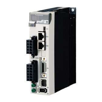
Product Name : AC servo driver
Part Number : MINAS-A5NL, A5N9 Series
Motor Business Unit, Appliances Company
Panasonic Corporation
7-1-1 Morofuku, Daito-City, Osaka 574-0044, Japan
Phone :
(072) 871-1212
Fax
:
(072) 870-3151
No. SX-DSV02308
Issued on
th
Mar. 6
, 2012
Revised on
Advertisement
Table of Contents

Related Manuals for Panasonic A5N9 Series


Summary of Contents for Panasonic A5N9 Series
- Page 1 No. SX-DSV02308 REFERENCE SPECIFICATIONS MODEL Product Name : AC servo driver Part Number : MINAS-A5NL, A5N9 Series Issued on Mar. 6 , 2012 Revised on Motor Business Unit, Appliances Company Panasonic Corporation 7-1-1 Morofuku, Daito-City, Osaka 574-0044, Japan Phone :...
- Page 2 No. SX-DSV02308 REVISIONS Date Page Rev. Description Signed NEWLY ISSUED Mar. 6, 2012 R1.0 Motor Business Unit, Appliances Company, Panasonic Corporation...
-
Page 3: Table Of Contents
XA , XB , XC , XD and Terminal Block .............21 7-2 USB Connector X1 .............................24 7-3 RTEX connectors X2A and X2B ......................25 7-4 Safety function connector X3 (for MINAS-A5N9 Series) ................25 7-5 I/O Connector X4 ............................26 7-6 Feedback Scale Connector X5 ........................28 7-7 CS signal Connector X6 ..........................28... -
Page 4: Scope
No. SX-DSV02308 - 1 - 1. Scope The specifications are for AC servo driver MINAS-A5NL Series and MINAS-A5N9 Series made by Motor Business Unit, Appliances Company, Panasonic Corporation. <Software version> This technical reference applies to the servo drivers compatible with software of the following version: Ver.8.01 or later... -
Page 5: Product Line-Up
33.1 83.7 (Note 1) MINAS-A5N9 Series are the models which are added the safety function to MINAS-A5NL series. (Note 2) For the applicable motor and feedback scale, also refer to the technical document SX-DSV02309. (Note 3) For the serial communication type of the rotary type, contact us. -
Page 6: Specifications
10–60 Hz (Continuous operation at resonance point is not allowed) 4-2 Compatible Standard (Under Contemplation) Item Description EMC directive EN55011 (CISPR11), EN61000-6-2, EN61800-3 Directive Low voltage directive EN61800-5-1 UL508C CSA22. 2 No.14 KN11 , KN61000-4-2,34,5,6,8,11 R1.0 Motor Business Unit, Appliances Company, Panasonic Corporation... -
Page 7: Dimensions
Option Standard Rack-mountable Base mounting type 2-M4 useful thread 4.7 (front mounting) (rear mounting) (an opposite side is the same) [Front mounting bracket Optional part number] Part number For frame A DV0PM20027 R1.0 Motor Business Unit, Appliances Company, Panasonic Corporation... - Page 8 Option Standard Rack-mountable Base mounting type (front mounting) (rear mounting) 2-M4 useful thread 4.7 (an opposite side is the same) [Front mounting bracket Optional part number] Part number For frame B DV0PM20028 R1.0 Motor Business Unit, Appliances Company, Panasonic Corporation...
- Page 9 Option Standard Rack-mountable Base mounting type 2-M4 useful thread 5.2 (front mounting) (rear mounting) (an opposite side is the same) [Front mounting bracket Optional part number] Part number For frame C DV0PM20029 R1.0 Motor Business Unit, Appliances Company, Panasonic Corporation...
- Page 10 2-M4 useful thread 4.65 (an opposite side is the same) Option Standard Rack-mountable Base mounting type (front mounting) (rear mounting) [Front mounting bracket Optional part number] Part number For frame D DV0PM20030 R1.0 Motor Business Unit, Appliances Company, Panasonic Corporation...
- Page 11 For base mounting type (rear mounting type), attach the mounting bracket to the rear surface. Although the above figure shows brackets attached to both the front and rear surfaces, the unit is shipped out with the bracket attached to only the front. R1.0 Motor Business Unit, Appliances Company, Panasonic Corporation...
- Page 12 For base mounting type (rear mounting type), attach the mounting bracket to the rear surface. Although the above figure shows brackets attached to both the front and rear surfaces, the unit is shipped out with the bracket attached to only the front. R1.0 Motor Business Unit, Appliances Company, Panasonic Corporation...
- Page 13 For base mounting type (rear mounting type), attach the mounting bracket to the rear surface. Although the above figure shows brackets attached to both the front and rear surfaces, the unit is shipped out with the bracket attached to only the front. R1.0 Motor Business Unit, Appliances Company, Panasonic Corporation...
- Page 14 No. SX-DSV02308 - 11 - Size H 200 V/400 V Name plate Mount Base mounting type (rear mounting) Mount R1.0 Motor Business Unit, Appliances Company, Panasonic Corporation...
-
Page 15: Appearance And Part Names
S05B-F32SK-GGXR (JST) or equivalent Main power source input terminal Control power source Charge lamp input terminal 06JFAT-SAXGF (JST) or equivalent Regenerative resistor S06B-F32SK-GGXR (JST) or connection terminal equivalent Motor connection terminal Earth terminal screw R1.0 Motor Business Unit, Appliances Company, Panasonic Corporation... - Page 16 Main power source input terminal Control power source input terminal Charge lamp 06JFAT-SAXGF (JST) or equivalent Regenerative resistor S06B-F32SK-GGXR (JST) connection terminal or equivalent (B2–B3: Normally short-circuited) Motor connection terminal Earth terminal screw R1.0 Motor Business Unit, Appliances Company, Panasonic Corporation...
- Page 17 Main power source or equivalent input terminal 04JFAT-SAXGSA-M(JST) Regenerative resistor or equivalent connection terminal S04B-JTSMSK-GSANXR(JST) (B2–B3: Normally or equivalent short-circuited) 03JFAT-SAXGSA-M(JST) Charge lamp or equivalent Motor connection terminal S03B-JTSMSK-GSANXR(JST) or equivalent Earth terminal screw R1.0 Motor Business Unit, Appliances Company, Panasonic Corporation...
- Page 18 Control power source input terminal 06JFAT-SAXGSA-L (JST) Regenerative resistor or equivalent connection terminal Charge lamp (B2–B3: Normally short-circuited) S03B-JTSLSK-GSANXR (JST) or equivalent Motor connection terminal 03JFAT-SAXGSA-L (JST) or equivalent Earth terminal screw R1.0 Motor Business Unit, Appliances Company, Panasonic Corporation...
- Page 19 S03B-JTSLSS-GSANYR(JST) or equivalent input terminal 04JFAT-SAXGSA-L(JST) Regenerative resistor or equivalent connection terminal (B2–B3: Normally S04B-JTSLSK-GSANXR(JST) short-circuited) or equivalent 03JFAT-SAXGSA-L(JST) or equivalent Charge lamp Motor connection terminal S03B-JTSLSK-GSANXR(JST) or equivalent Earth terminal screw R1.0 Motor Business Unit, Appliances Company, Panasonic Corporation...
- Page 20 Main power source input terminal Control power source input terminal Regenerative resistor connection terminal (B2–B3: Normally short-circuited) Motor connection terminal Charge lamp Earth terminal screw Note: Terminal block with the cover removed R1.0 Motor Business Unit, Appliances Company, Panasonic Corporation...
- Page 21 Control power source input terminal Main power source input terminal Regenerative resistor connection terminal (B2–B3: Normally short-circuited) Motor connection terminal Charge lamp Earth terminal screw Note: Terminal block with the cover removed R1.0 Motor Business Unit, Appliances Company, Panasonic Corporation...
- Page 22 External dynamic brake resistor control terminal Motor connection DB3–DB4: Normally short-circuited terminal (Open: When external dynamic brake resistor is connected) Charge lamp Earth terminal screw Note: Terminal block with the cover removed R1.0 Motor Business Unit, Appliances Company, Panasonic Corporation...
- Page 23 L1 L2 L3 B1 B2 U V W Main power Regenerative Motor Terminal Block (lower side) source input resistor connection terminal connection terminal Earth terminal screw Note: Terminal block with the cover removed R1.0 Motor Business Unit, Appliances Company, Panasonic Corporation...
-
Page 24: Configuration Of Connectors And Terminal Blocks
Connect the one terminal to ground, and the other to the E terminal of a motor. Do not connect more than one wire to a grounding terminal. • Refer to section 9-3 for the tightening torque of the screw. R1.0 Motor Business Unit, Appliances Company, Panasonic Corporation... - Page 25 Do not connect more than one wire to a grounding terminal. • Refer to section 9-3 for the tightening torque of the screw. • Tighten the fixing screw of the terminal block cover with a torque 0.2 N•m or lower. R1.0 Motor Business Unit, Appliances Company, Panasonic Corporation...
- Page 26 Do not connect more than one wire to a grounding terminal. • Refer to section 9-3 for the tightening torque of the screw. • Tighten M3 terminal block cover fixing screw with the 0.2 N•m torque. R1.0 Motor Business Unit, Appliances Company, Panasonic Corporation...
-
Page 27: Usb Connector X1
Connector Name Symbol Description pin no. VBUS Communicate with a computer USB signal • For manufacturer use • Do not connect Signal ground • Signal ground R1.0 Motor Business Unit, Appliances Company, Panasonic Corporation... -
Page 28: Rtex Connectors X2A And X2B
Frame ground Shell Connect to shield of cable. • Be sure to use shielded twisted pair (STP) compatible with 5e of TIA/EIA-568 or higher category. 7-4 Safety function connector X3 (for MINAS-A5N9 Series) For the safety function connector. Connector I/O type... -
Page 29: I/O Connector X4
• Use a shielded twisted-pair cable for wiring, and connect the shield wire to the connector shell. • Signal ground Signal ground — • Be sure to connect the ground of the line receiver to this terminal. R1.0 Motor Business Unit, Appliances Company, Panasonic Corporation... - Page 30 Name Symbol Description I/O type pin no. 14, 15 Reserved — • Do not connect — 23, 24 Frame ground Shell • Connected to the earth terminal in the servo driver. — R1.0 Motor Business Unit, Appliances Company, Panasonic Corporation...
-
Page 31: Feedback Scale Connector X5
EX5V power supply output for feedback scale and E5V power supply output for CS signal are rated at 5.2 V 5% and 300 Note 2: mA at maximum. To use an feedback scale and CS signal with a current consumption higher than that, a preparation of an external power supply is required. R1.0 Motor Business Unit, Appliances Company, Panasonic Corporation... -
Page 32: Monitor Connector X7
Analog monitor output 2 —SX-DSV02309. Signal ground • Signal ground Reserved • Do not connect Reserved • Do not connect Reserved • Do not connect R1.0 Motor Business Unit, Appliances Company, Panasonic Corporation... - Page 33 Output signal amplitude is 10V Do-1 Equivalent of AM26C31 + - +: Pins 17, 20, 21, -: Pins 18, 19, 22 Connect a terminating resistor (approx. 330 Ω) between the input terminals of the line receiver. R1.0 Motor Business Unit, Appliances Company, Panasonic Corporation...
- Page 34 CS signal interface CN X6 CS sensor SN74LV14APW or equivalent +5.2V CS-GND EX5V EX0V (Note) Refer to technical document SX-DSV02309 for the relation of the move direction of CS signal and the linear motor. R1.0 Motor Business Unit, Appliances Company, Panasonic Corporation...
-
Page 35: Wiring
Solder plug 10126-3000PE (soldering type) Sumitomo 3M Shell kit 10326-52A0-008 Connector MUF-PK10K-X J. S. T. Mfg 3E206-0100KV Connector Sumitomo 3M 3E306-3200-008 Connector 51004-0600 Molex Connector pin 50011-8100 Use connectors listed above or equivalents. R1.0 Motor Business Unit, Appliances Company, Panasonic Corporation... -
Page 36: Precautions For Wiring
Main power Power supply (3-phase) supply Control power supply External regenerative resistor Short cable Detach it when using an external regenerative resistor (Sizes C,D). White Motor Connection Black Green ALM+ 12–24 VDC ALM- R1.0 Motor Business Unit, Appliances Company, Panasonic Corporation... - Page 37 MCCB Main power Power supply (3-phase) supply Control power supply External regenerative resistor Short cable Detach it when using an external regenerative resistor White Motor Connection Black Green ALM+ 12–24 VDC ALM- R1.0 Motor Business Unit, Appliances Company, Panasonic Corporation...
- Page 38 + 24V dc power Control power supply supply - External regenerative resistor Short cable Detach it when using an external regenerative resistor White Motor Connection Black Green ALM+ 12-24 VDC ALM- R1.0 Motor Business Unit, Appliances Company, Panasonic Corporation...
- Page 39 MCCB Main power supply Power supply (3-phase) Control power supply Short cable Detach it when using an external regenerative resistor External regenerative resistor White Motor Connection Black Green ALM+ 12–24 VDC ALM- R1.0 Motor Business Unit, Appliances Company, Panasonic Corporation...
- Page 40 Power supply (3-phase) Control power supply 24V dc power + supply - Short cable Detach it when using an external regenerative resistor External regenerative resistor White Motor Connection Black Green ALM+ 12–24 VDC ALM- R1.0 Motor Business Unit, Appliances Company, Panasonic Corporation...
- Page 41 MCCB Power supply Main power (3-phase) supply Control power supply External regenerative resistor Short ber Detach it when using an external regenerative resistor White Motor Connection Black Green ALM+ 12-24 VDC ALM- R1.0 Motor Business Unit, Appliances Company, Panasonic Corporation...
- Page 42 Control 24V dc power + power supply supply - External regenerative resistor Short ber Detach it when using an external regenerative resistor White Motor Connection Black Green ALM+ 12-24 VDC ALM- R1.0 Motor Business Unit, Appliances Company, Panasonic Corporation...
- Page 43 White Motor Connection Black Green Servo may be turned on in the external sequence if the dynamic brake resistor deposits to protect the system, provide the auxiliary contact. ALM+ 12-24 VDC ALM- R1.0 Motor Business Unit, Appliances Company, Panasonic Corporation...
- Page 44 White Motor Connection Black Green Servo may be turned on in the external sequence if the dynamic brake resistor deposits to protect the system, provide the auxiliary contact. ALM+ 12-24 VDC ALM- R1.0 Motor Business Unit, Appliances Company, Panasonic Corporation...
- Page 45 [14] In order to reduce the terminal noise voltage, install a noise filter. [15] Turn ON the power after the wiring was finished. R1.0 Motor Business Unit, Appliances Company, Panasonic Corporation...
- Page 46 • Install the regenerative resistor so that people cannot directly touch it, such as the incombustible to cover it. • Keep the temperature of places, which people can directly touch, below 70 deg. Celsius. R1.0 Motor Business Unit, Appliances Company, Panasonic Corporation...
- Page 47 Insert only 1 wire into a wire insertion opening. • Connected wire can be removed in the same way as it is inserted. • Be careful not to be injured when using a screwdriver. R1.0 Motor Business Unit, Appliances Company, Panasonic Corporation...
- Page 48 4.7k 4.7k 4.7k 4.7k 12-24 VDC 4.7k 4.7k Servo driver side The functions of the pins SI1-SI8 are assigned by parameters. For factory default settings, refer to Appendix “Specification for Each Model”. R1.0 Motor Business Unit, Appliances Company, Panasonic Corporation...
- Page 49 AM26C32 or equivalent AM26C31or equivalent Servo driver side Note: [1] To receive the output pulse, use RS422 line receiver (AM26C32 or equivalent), with an appropriate termination resistor (approx. 330 ) connected across its inputs. R1.0 Motor Business Unit, Appliances Company, Panasonic Corporation...
- Page 50 [9] When using a magnet pole position estimation function without CS signal, wiring of X6 is unnecessary. The example of A/B phase, differential origin signal input type wiring EX5V EX0V Detection head Feedback scale unit CS-GND Cable side Feedback scale side Servo driver side R1.0 Motor Business Unit, Appliances Company, Panasonic Corporation...
- Page 51 No. SX-DSV02308 - 48 - The example of serial communication type wiring EX5V EX0V EXPS EXPS Detection head Feedback scale unit CS-GND Feedback scale side Cable side Servo driver side R1.0 Motor Business Unit, Appliances Company, Panasonic Corporation...
- Page 52 (Note 2) Do not connect with EX5V pin. And do not supply EX5V pin with power supply from the exterior. External power source EX0V Detection head Feedback scale unit CS-GND Feedback scale side Cable side Servo driver side R1.0 Motor Business Unit, Appliances Company, Panasonic Corporation...
- Page 53 White/Orange Orange White/Blue Blue White/Brown Brown Shield on connector Shield on connector Higher-level device or servo driver in the Shielded twisted pair cable of 5e or higher category Servo driver preceding circuit R1.0 Motor Business Unit, Appliances Company, Panasonic Corporation...
- Page 54 White/Brown Brown Shield on connector Shield on connector Higher-level device or servo driver in the Shielded twisted pair cable of 5e or higher category Servo driver subsequent circuit Pins on RJ45 plug R1.0 Motor Business Unit, Appliances Company, Panasonic Corporation...
-
Page 55: Compliance With European Ec Directive/Ul Standard
UL standard UL508C (File No. E164620) CSA standard C22. 2 No. 14 International Electrotechnical Commission Europaischen Norman EMC : Electromagnetic Compatibility Under writers Laboratoris CSA : Canadian Standards Association International Organization for Standardization R1.0 Motor Business Unit, Appliances Company, Panasonic Corporation... -
Page 56: Peripheral Device Configuration
24 V dc power Surge scale supply absorber Noise filter for signal line Noise filter for signal line RTEX Insulated type I/O communication power supply I/O controller Safety controller Protection ground (PE) R1.0 Motor Business Unit, Appliances Company, Panasonic Corporation... - Page 57 (PE) of the control panel. (2) Do not tighten the connection to the ground terminal ( ) along with other parts. The servo driver has two ground terminals. R1.0 Motor Business Unit, Appliances Company, Panasonic Corporation...
-
Page 58: List Of Peripheral Devices Applicable To Servo Driver
To become compliant with European EC directive, make sure to connect a circuit breaker compliant with IEC standard and UL certification (marked with LISTED) between the power supply and the noise filter. R1.0 Motor Business Unit, Appliances Company, Panasonic Corporation... - Page 59 RJ8095 T400-61D MICROMETALS - DV0P4170 SUP-EK5-ER-6 DV0P4180 3SUP-HQ10-ER-6 DV0P4220 3SUP-HU30-ER-6 Okaya Electric Industries DV0P3410 3SUP-HL50-ER-6B DV0PM20042 3SUP-HU10-ER-6 DV0PM20043 3SUP-HU50-ER-6 Noise filter FN258L-16-07(29) - - FN258L-30-07(33) Schaffner - FS5559-60-34 FS5559-80-34 - FN258-42-07(33) - R1.0 Motor Business Unit, Appliances Company, Panasonic Corporation...
-
Page 60: Compliance With Ul Standard
[2] Make sure to evaluate and confirm the compliance with F47 power supply instantaneous stop standard with an actual device. 11. Compliance with KC mark Conformity of Korea Certification mark is registered by suiting EMC directive. Registration No.KCC-REM-FAN-M-D R1.0 Motor Business Unit, Appliances Company, Panasonic Corporation... -
Page 61: Safety Precautions
(10) Motor servo driver heat sink and peripheral device become very hot. Do not touch them. Do not carry out wiring or do not operate the equipment with wet hands. (11) (12) Wiring work is strictly allowed only for an engineer specializing electrical work. R1.0 Motor Business Unit, Appliances Company, Panasonic Corporation... - Page 62 (26) Be sure not to use the electromagnetic contactor installed on the main power supply to start or stop the motor. (27) Avoid frequent switching on and off the main power supply of the servo driver. R1.0 Motor Business Unit, Appliances Company, Panasonic Corporation...
- Page 63 5 years. Commission the manufacturer or sales agency authorized by the manufacturer to replace the parts. Be sure to read the operating manual (safety book) before use. R1.0 Motor Business Unit, Appliances Company, Panasonic Corporation...
- Page 64 (include radiation) or static electricity, or a defect of the input power supply, wiring or components may cause the servo driver to operate beyond the preset conditions. Therefore, you should exercise thorough caution to ensure safety against an unexpected operation. R1.0 Motor Business Unit, Appliances Company, Panasonic Corporation...
-
Page 65: Life And Warranty
This warranty shall be exempted when the life of component exceeds its rated standard life. (2) Warranty scope Panasonic warrants the replacement of the defected parts of the product or repair of them when the defects of the product occur during the warranty period, and when the defects are under Panasonic responsibility. This warranty only covers the product itself and does not cover any damage incurred by such defects. -
Page 66: Others
When discarding the equipment, process the item as an industrial waste. Carry out matching of a linear motor and servo driver and the checking of safety in the responsibility of your company. R1.0 Motor Business Unit, Appliances Company, Panasonic Corporation... - Page 67 ・ When an unexpected trouble occurs at the matching of motor, distributor, motor manufacture, and machine manufacture is to correspond the trouble in good faith.in good faith R1.0 Motor Business Unit, Appliances Company, Panasonic Corporation...
-
Page 68: Specification For Each Model
Dimensions Size A Size A Size A Size A Current values were calculated on the basis of the power supply input described above, assuming a voltage of 100 V or 200 V. R1.0 Motor Business Unit, Appliances Company, Panasonic Corporation... - Page 69 Approx. 1.0 kg Approx. 1.0 kg Dimensions Size B Size B Current values were calculated on the basis of the power supply input described above, assuming a voltage of 100 V or 200 V. R1.0 Motor Business Unit, Appliances Company, Panasonic Corporation...
- Page 70 Approx.1.6 kg Approx.1.6 kg Dimensions Size C Size C Current values were calculated on the basis of the power supply input described above, assuming a voltage of 100 V or 200 V. R1.0 Motor Business Unit, Appliances Company, Panasonic Corporation...
- Page 71 Size D Size D Size D Current values were calculated on the basis of the power supply input described above, assuming a voltage of 200 V, 400 V or 24 V dc. R1.0 Motor Business Unit, Appliances Company, Panasonic Corporation...
- Page 72 Approx. 2.7 kg Dimensions Size E Size E Current values were calculated on the basis of the power supply input described above, assuming a voltage of 200 V, 400 V or 24 V dc. R1.0 Motor Business Unit, Appliances Company, Panasonic Corporation...
- Page 73 Size F Size F Size F Current values were calculated on the basis of the power supply input described above, assuming a voltage of 200 V, 400 V or 24 V dc. R1.0 Motor Business Unit, Appliances Company, Panasonic Corporation...
- Page 74 Size G Size G Size H Size H Current values were calculated on the basis of the power supply input described above, assuming a voltage of 200 V, 400V and 24 V dc. R1.0 Motor Business Unit, Appliances Company, Panasonic Corporation...
- Page 75 Dimensions Size A Size A Size A Size A Current values were calculated on the basis of the power supply input described above, assuming a voltage of 100 V or 200 V. R1.0 Motor Business Unit, Appliances Company, Panasonic Corporation...
- Page 76 Approx. 1.0 kg Approx. 1.0 kg Dimensions Size B Size B Current values were calculated on the basis of the power supply input described above, assuming a voltage of 100 V or 200 V. R1.0 Motor Business Unit, Appliances Company, Panasonic Corporation...
- Page 77 Approx.1.6 kg Approx.1.6 kg Dimensions Size C Size C Current values were calculated on the basis of the power supply input described above, assuming a voltage of 100 V or 200 V. R1.0 Motor Business Unit, Appliances Company, Panasonic Corporation...
- Page 78 Size D Size D Size D Current values were calculated on the basis of the power supply input described above, assuming a voltage of 200 V, 400 V or 24 V dc. R1.0 Motor Business Unit, Appliances Company, Panasonic Corporation...
- Page 79 Approx. 2.7 kg Dimensions Size E Size E Current values were calculated on the basis of the power supply input described above, assuming a voltage of 200 V, 400 V or 24 V dc. R1.0 Motor Business Unit, Appliances Company, Panasonic Corporation...
- Page 80 Size F Size F Size F Current values were calculated on the basis of the power supply input described above, assuming a voltage of 200 V, 400 V or 24 V dc. R1.0 Motor Business Unit, Appliances Company, Panasonic Corporation...
- Page 81 Size G Size G Size H Size H Current values were calculated on the basis of the power supply input described above, assuming a voltage of 200 V, 400V and 24 V dc. R1.0 Motor Business Unit, Appliances Company, Panasonic Corporation...
- Page 82 External latch input 3 NO contact SI-MON4 General monitor input 4 NO contact BRK-OFF External brake release signal NO contact 25,26 EX-OUT1 RTEX operation output 1 NO contact Alarm output NC contact R1.0 Motor Business Unit, Appliances Company, Panasonic Corporation...
- Page 83 [Default value of the parameters(1/3)] No. SX-DSV02308 PARAMETER MINAS-A5NL and A5N9 series all common MODEL Cate Cate Cate Cate Cate Parameter Default value Parameter Default value Parameter Default value Parameter Default value Parameter Default value gory gory gory gory gory...
- Page 84 [Default value of the parameters(2/3)] No. SX-DSV02308 PARAMETER MINAS-A5NL and A5N9 series all common MODEL Cate Cate Cate Cate Cate Parameter Default value Parameter Default value Parameter Default value Parameter Default value Parameter Default value gory gory gory gory gory...
- Page 85 [Default value of the parameters(3/3)] No. SX-DSV02308 PARAMETER MINAS-A5NL and A5N9 series all common MODEL Cate Cate Cate Cate Cate Parameter Default value Parameter Default value Parameter Default value Parameter Default value Parameter Default value gory gory gory gory gory Thrust command filter for estimating 1.00...