
Related Manuals for Mitsubishi Electric QJ71DN91


Summary of Contents for Mitsubishi Electric QJ71DN91
- Page 1 DeviceNet Master-Slave Module User's Manual -QJ71DN91 -GX Configurator-DN (SW1D5C-QDNU-E)
-
Page 3: Safety Precautions
WARNING If a communications error occurs on a DeviceNet network, faulty nodes will behave as follows: (1) The master node (QJ71DN91) holds input data which had been received from slave nodes before the error occurred. (2) Whether output signals of a slave node are turned off or held is determined by the slave node's specifications or the parameters set at the master node. -
Page 4: Wiring Precautions
[INSTALLATION PRECAUTIONS] CAUTION Use the programmable controller in an environment that meets the general specifications contained in the User's Manual of the CPU module used. Using it in an environment that does not meet them may result in an electric shock, fire, malfunction, and damage to or deterioration of the product. - Page 5 [STARTUP/MAINTENANCE PRECAUTIONS] DANGER Do not touch any terminal unless all phases of the external power supply have been shut off. Doing so may cause a malfunction. Always turn off all phases of the external power supply before cleaning or retightening the terminal screws.
-
Page 6: Conditions Of Use For The Product
CONDITIONS OF USE FOR THE PRODUCT (1) Mitsubishi programmable controller ("the PRODUCT") shall be used in conditions; i) where any problem, fault or failure occurring in the PRODUCT, if any, shall not lead to any major or serious accident; and ii) where the backup and fail-safe function are systematically or automatically provided outside of the PRODUCT for the case of any problem, fault or failure occurring in the PRODUCT. -
Page 7: Revisions
REVISIONS *The manual number is given on the bottom left of the back cover. Print Date *Manual Number Revision Dec. 2000 SH (NA)-080143-A First Printing Jun. 2001 SH (NA)-080143-B Addition Section 2.3, 2.4 Delete Section 2.2.1, 2.2.2 Correction SAFETY PRECAUTIONS, About the Generic Terms and Abbreviations, Product Configuration, Section 2.2, 2.4, Section 6.2, 6.2.1, 6.2.2, 6.3.3, Feb. - Page 8 This manual confers no industrial property rights or any rights of any other kind, nor does it confer any patent licenses. Mitsubishi Electric Corporation cannot be held responsible for any problems involving industrial property rights which may occur as a result of using the contents noted in this manual.
-
Page 9: Table Of Contents
INTRODUCTION Thank you for purchasing the MELSEC-Q series programmable controller. Before using the product, please read this manual carefully to understand the functions and performance of the Q series programmable controller to ensure correct use. CONTENTS SAFETY PRECAUTIONS ..........................A- 1 CONDITIONS OF USE FOR THE PRODUCT ..................... - Page 10 3.4.11 Own node information area ......................3-42 3.4.12 Hardware test area .......................... 3-43 3.4.13 Parameter saving area selection area.................... 3-45 3.4.14 Auto communication start setting area ................... 3-45 3.4.15 Operation Setting Area For Bus Off Error ..................3-46 3.4.16 Data consistency dedicated instruction area ................. 3-47 3.5 Communication Performance ........................
- Page 11 6.5.2 Parameter area monitor/test ......................6-20 6.5.3 Save parameters to flash ROM ......................6-21 6.5.4 Node configuration status monitor ....................6-22 6.5.5 Node communication status monitor ....................6-22 6.5.6 Node communication error status monitor ..................6-23 6.5.7 Node fault status monitor ........................6-23 6.5.8 Failed node detection setting ......................
- Page 12 Appendix 4 The Comparison of Operation Between GX Configurator-DN and GX Works2 ....App- 7 Appendix 5 How to Use the QJ71DN91 in System of MELSEC iQ-R Series ..........App- 8 Appendix 6 Parameter Setting Sheet (For the Master Function) .............App- 9 Appendix 7 Parameter Setting Sheet (For the Slave Function) ..............
-
Page 13: Compliance With The Emc And Low Voltage Directives
COMPLIANCE WITH THE EMC AND LOW VOLTAGE DIRECTIVES (1) Method of ensuring compliance To ensure that Mitsubishi programmable controllers maintain EMC and Low Voltage Directives when incorporated into other machinery or equipment, certain measures may be necessary. Please refer to one of the following manuals. ... -
Page 14: Generic Terms And Abbreviations
GENERIC TERMS AND ABBREVIATIONS Unless otherwise specified, this manual uses the following generic terms and abbreviations to explain the QJ71DN91 DeviceNet master/slave module. Generic term/abbreviation Description GX Developer The product name of the software package for the MELSEC programmable controllers... -
Page 15: Definitions Of Terminology
Master/slave node Parameters for setting information such as connection type or I/O points, which are used to Master function exchange I/O data with respective slave nodes when the QJ71DN91 is used as a master parameters node. Configured in sequence programs or GX Configurator-DN. -
Page 16: Packing List
PACKING LIST The following are included in the package. Model Product name Quantity QJ71DN91 DeviceNet master/slave module QJ71DN91 Terminating resistor 121 , 1/4W Connector SW1D5C-QDNU-E GX Configurator-DN Version 1 (single license product) (CD-ROM) SW1D5C-QDNU-EA GX Configurator-DN Version 1 (volume license product) -
Page 17: Overview
Volumes 1 and 2. DeviceNet is a registered trademark of Open DeviceNet Vendor Association, Inc. POINT The QJ71DN91 is assumed to be compatible with most of DeviceNet products on the market. However, the compatibility with products manufactured by other vendors is not guaranteed. - Page 18 1 OVERVIEW MELSEC-Q Message communication function (Refer to Section 4.2.) Using the buffer memory of the QJ71DN91, attribute data can be read from or written to slave nodes. For details of other message communications, refer to the DeviceNet common service in the DeviceNet Specifications (Release2.0).
- Page 19 No communication between DeviceNet slaves (4) Preventing inconsistency of I/O data When I/O data is read from/written to the buffer memory of the QJ71DN91, data inconsistency can be avoided using Data consistency dedicated instruction (DNTMRD, DNTMWR, DNTSRD, DNTSWR). (Refer to Chapter 9.)
-
Page 20: System Configuration
The number of modules connectable to a DeviceNet network is 64, including master, slave and master/slave nodes. The QJ71DN91 can be used as a master node, a slave node or a master/slave node. The following shows an example of a system configuration:... - Page 21 2 SYSTEM CONFIGURATION MELSEC-Q Remarks Please inquire to ODVA about the following devices that are required to construct a DeviceNet network. • Network power supply unit • Power supply tap • Tap • Terminating resistor • DeviceNet cable Contact: Open DeviceNet Vendor Association, Inc. http://www.odva.org/ 2 - 2 2 - 2...
-
Page 22: Applicable Systems
When mounted with a CPU module The table below shows the CPU modules and base units applicable to the QJ71DN91 and quantities for each CPU model. Depending on the combination with other modules or the number of mounted modules, power supply capacity may be insufficient. - Page 23 *1: Limited within the range of I/O points for the CPU module. *2: Can be installed to any I/O slot of a base unit. *3: Use the QJ71DN91 whose serial number (first five digits) is 03052 or later. Mounting to a MELSECNET/H remote I/O station The QJ71DN91 cannot be mounted to any MELSECNET/H remote I/O station.
- Page 24 2 SYSTEM CONFIGURATION MELSEC-Q (2) Support of the multiple CPU system When using the QJ71DN91 in a multiple CPU system, refer to the QCPU User’s Manual (Multiple CPU System) first. 2 - 5 2 - 5...
- Page 25 2 SYSTEM CONFIGURATION MELSEC-Q (3) Supported software packages Relation between the system containing the QJ71DN91 and software package is shown in the following table. To use the QJ71DN91, GX Developer or GX Works2 is required. Software version GX Developer Configurator-DN...
- Page 26 Appendix 4. (4) Remote operation is not allowed from another DeviceNet node Each DeviceNet node on DeviceNet cannot read/write/monitor the sequence program or data of the programmable controller CPU where the QJ71DN91 is installed. 2 - 7 2 - 7...
-
Page 27: How To Check The Function Version, Serial Number And Software Version
This section describes how to check the function version and serial number of the QJ71DN91 and GX Configurator-DN software version. (1) Checking the function version and serial number of the QJ71DN91 Checking at "the SERIAL field of the rating plate" located on the side of the... - Page 28 Function version Serial No. Product No. Product number display Since the QJ71DN91 does not support the product number display, "-" is displayed. POINT The serial No. displayed in the Product Information List of GX Developer may be different from the one on the rating plate and the front of the module.
- Page 29 2 SYSTEM CONFIGURATION MELSEC-Q (2) Checking the software version of GX Configurator-DN To check the software version of GX Configurator-DN, select "Help" and then "Product information" from GX Developer. Software version (In the case of GX Developer Version 8) 2 - 10 2 - 10...
-
Page 30: Precautions On System Configuration
2.4 Precautions on System Configuration (1) DeviceNet products manufactured by other vendors The QJ71DN91 is assumed to be compatible with most of the DeviceNet products on the market. However, the compatibility with products manufactured by other vendors is not guaranteed. -
Page 31: Specifications
This chapter provides the performance specifications of the QJ71DN91, I/O signals used with a programmable controller CPU, and buffer memory specifications. For the general specifications for the QJ71DN91, refer to the User’s Manual (Hardware) of the CPU module used. 3.1 Performance Specifications Table 3.1 shows the performance specifications of the QJ71DN91. -
Page 32: Maximum Trunk Line Distance When Using Thick And Thin Cables
3 SPECIFICATIONS MELSEC-Q 3.1.1 Maximum trunk line distance when using thick and thin cables The maximum transmission distance in the case of using thick and thin cables is shown below. Table 3.2 Maximum trunk line distance when using thick and thin cables Maximum trunk line distance when using thick Communication speed and thin cables... -
Page 33: Function Lists
The connection type is selectable for each slave node. Master function The QJ71DN91 master node can read attribute data from or write them to slave nodes, using its own buffer memory. Message For further details, refer to the DeviceNet common service in communication the DeviceNet Specifications (Release2.0). -
Page 34: I/O Signals For Programmable Controller Cpu
3 SPECIFICATIONS MELSEC-Q 3.3 I/O Signals for Programmable Controller CPU This section explains the input/output signals that the QJ71DN91 sends to or receives from a programmable controller CPU. 3.3.1 I/O signal list The I/O signal assignments shown are based on the case where the start I/O No. of the QJ71DN91 is "0000"... -
Page 35: I/O Signals For The Master Function
This section describes the on/off timings and conditions of the I/O signals used for the master function. (1) Watchdog Timer Error (X00) This is set to on when a hardware failure occurs in the QJ71DN91. OFF: Module normal Module error When Watchdog Timer Error (X00) is set to on, Module Ready (X0F) is set to off. - Page 36 3 SPECIFICATIONS MELSEC-Q When parameter check failed Module Ready (X0F) I/O Communication Request (Y11) I/O Communicating (X01) Error Set Signal for Master Function (X03) Parameter check POINT (1) I/O Communicating (X01) is not set to on even if I/O Communication Request (Y11) is turned on with the following output signals set to on, •...
- Page 37 3 SPECIFICATIONS MELSEC-Q When starting I/O communication automatically at power-up Set "Start" in Automatic Communication Start Setting (address: 0631 • When power is turned on, Module Ready (X0F) is set to on and parameters are checked. • If the parameter check is completed successfully, I/O communication with each slave node is started and I/O Communicating (X01) is set to on.
- Page 38 3 SPECIFICATIONS MELSEC-Q (3) Message Communication Completion (X02), Message Communication Error Signal (X05), Message Communication Request (Y12) These signals are used for message communication. Execute each signal action when Master Function Communication Status (address: 01B0 ) is "OPERATE )" or "STOP (40 )".
- Page 39 3 SPECIFICATIONS MELSEC-Q (4) Error Set Signal for Master Function (X03), Error Reset Request for Master Function (Y13) These signals are used for notification of an error occurred during master function execution and for error code resetting. When a master function error occurs, the error information is stored in Error Information for Master Function (address: 01B1 ), and Error Set Signal for Master Function (X03) is set to on.
- Page 40 3 SPECIFICATIONS MELSEC-Q (6) Saving Parameters to Flash ROM (X06), Parameters Saved to Flash ROM (X07), Request for Saving Parameters to Flash ROM (Y17) These signals are used to save the parameters in the buffer memory to the flash ROM. Execute each signal action while I/O Communicating (X01) is off. When Request for Saving Parameters to Flash ROM (Y17) is set to on, parameters are checked.
- Page 41 (7) Module Ready (X0F) This signal indicates whether or not the QJ71DN91 is operable. When the QJ71DN91 is ready to operate, it is set to on. When Watchdog Timer Error (X00) turns on, this Module Ready (X0F) is set to off.
- Page 42 3 SPECIFICATIONS MELSEC-Q (8) Auto-Configuring (X14), Auto Configuration Completion (X15), Auto Configuration Request (Y15) These signals are used to configure parameters automatically. Execute them while I/O Communicating (X01) is off. When Auto Configuration Request (Y15) is set to on, auto configuration starts and Auto-Configuring (X14) is set to on.
-
Page 43: I/O Signals For The Slave Function
3 SPECIFICATIONS MELSEC-Q 3.3.3 I/O signals for the slave function This section describes the on/off timings and conditions of the I/O signals used for the slave function. (1) Watchdog Timer Error (X00) Refer to Section 3.3.2 (1). (2) I/O Communicating (X01), I/O Communication Request (Y11) These are used to start I/O communication with a master node. - Page 44 3 SPECIFICATIONS MELSEC-Q When parameter check failed Module Ready (X0F) I/O Communication Request (Y11) I/O Communicating (X01) Error Set Signal for Slave Function (X08) Parameter check POINT (1) I/O Communicating (X01) is not set to on even if I/O Communication Request (Y11) is turned on with the following output signals set to on, •...
- Page 45 3 SPECIFICATIONS MELSEC-Q When starting I/O communication automatically at power-up Set "Start" in Automatic Communication Start Setting (address: 0631 • When power is turned on, Module Ready (X0F) is set to on and parameters are checked. • If the parameter check is completed successfully, I/O communication with the master node is started and I/O Communicating (X01) is set to on.
- Page 46 3 SPECIFICATIONS MELSEC-Q (4) Error Set Signal for Slave Function (X08), Error Reset Request for Slave Function (Y18) These signals are used for notification of an error occurred during slave function execution and for error code resetting. When a slave function error occurs, the error information is stored in Error Information for Slave Function (address: 0601 ), and Error Set Signal for Slave Function (X08) is set to on.
-
Page 47: Buffer Memory
3 SPECIFICATIONS MELSEC-Q 3.4 Buffer Memory This section explains the buffer memory of the QJ71DN91. 3.4.1 Buffer memory list The buffer memory list is shown in Table 3.6. Table 3.6 Buffer memory list (1/3) Address Availability Reference Item Description Read/Write *1... - Page 48 0631 1585 3.4.14 Setting *2 the flash ROM at the time of power on from off or CPU reset. Set whether or not to reset the QJ71DN91’s Operation Setting Area for CAN chip (communication chip) to restart 0632 1586 3.4.15...
- Page 49 3 SPECIFICATIONS MELSEC-Q Table 3.6 Buffer memory list (3/3) Address Availability Reference Item Description Read/Write *1 Master Slave Hex. Dec. section function function 0B40 2880 to 3071 Use prohibited — — — — — 0BFF 0C00 Slave Function Transmit 3072 to 3135 Data to be sent to the master node is set.
-
Page 50: Message Communication Area For Master Function
3 SPECIFICATIONS MELSEC-Q 3.4.2 Message communication area for master function This area is used for the message communication of the master function. For the execution timing, refer to Section 3.3.2 (3). (1) Message Communication Command (address: 0110 to 011F /272 to 287) Set a command for message communication. - Page 51 3 SPECIFICATIONS MELSEC-Q Other message communications Data to be set are shown below. For details, refer to DeviceNet common service in the DeviceNet Specifications (Release2.0). Table 3.11 Other message communications Buffer memory address Item Description (Hex.) 0110 Command No. FE** : Refer to DeviceNet Common Service for**.
- Page 52 3 SPECIFICATIONS MELSEC-Q Reading communication error information of a slave node Table 3.14 Read communication error information Buffer memory Item Description address (Hex.) 0120 Command No. 0001 =Read communication error information Normal completion: 0000 0121 Execution error code Failed: Execution error code (Refer to Section 10.2.2.) Resetting Table 3.15 Reset Buffer memory...
- Page 53 3 SPECIFICATIONS MELSEC-Q (3) Message Communication Data (address: 0130 to 01A7 /304 to 423) This area stores data sent/received by message communications. Getting attribute data of a slave node Attribute data is stored in units of bytes. 0130 2nd byte 1st byte 4th byte 3rd byte...
- Page 54 Stores an additional error code sent from the slave 0134 Additional error code node. *2 Stores the number of times the QJ71DN91 has 0135 Heartbeat timeout count detected failure of each slave node. *1: Refer to the manual of each slave node for actual failures and troubleshooting.
-
Page 55: Own Node Status Area For Master Function
3 SPECIFICATIONS MELSEC-Q 3.4.3 Own node status area for master function This area stores the communication status, error information, etc. of the master function. (1) Master Function Communication Status (address: 01B0 /432) The communication status of the master function is stored. High byte The I/O communication status of the master station is stored. - Page 56 3 SPECIFICATIONS MELSEC-Q Low byte The communication status of the network is stored. Depending on the communication status, each bit turns on/off as shown below. Bit 7 Bit 6 Bit 5 Bit 4 Bit 3 Bit 2 Bit 1 Bit 0 A faulty node exists.
- Page 57 An increase of this value means that communications are unreliable. (4) Bus Off Counter (address: 01B3 /435) The number of times that the QJ71DN91 was placed in the bus off status is stored. An increase of this value means that communications are unreliable.
-
Page 58: Node Status Area For Master Function
3 SPECIFICATIONS MELSEC-Q 3.4.4 Node status area for master function The operation status of each slave node is stored in this area. (1) Node Configuration Status (address: 01B4 to 01B7 /436 to 439) The parameter setting status of each slave node is stored. •... - Page 59 3 SPECIFICATIONS MELSEC-Q (3) Node Communication Error Status (address: 1C0 to 1C3 /448 to 451) The I/O communication error status of each slave node is stored. While I/O Communicating (X01) is off, all bits are off. Note that no error is detected for the node whose corresponding bit is on in Failed Node Detection Setting (address: 01CC to 01CF •...
- Page 60 3 SPECIFICATIONS MELSEC-Q (5) Failed Node Detection Setting (address: 01CC to 01CF /460 to 463) Whether or not to detect a failed node is set in this area. The setting determines whether or not the off status in Node Communication Status (address: 01BC to 01BF ) is reflected to Slave Down Signal (X04).
-
Page 61: Master Function Parameter Setting Area
3 SPECIFICATIONS MELSEC-Q 3.4.5 Master function parameter setting area Parameters for master function are set in this area. To exchange I/O data with each slave node (up to 63 nodes), information such as connection types and I/O points is set. (1) Parameters for Master Function (address: 01D4 to 03CF /468 to... - Page 62 3 SPECIFICATIONS MELSEC-Q Buffer memory Item Description address (Hex.) Set an action for watchdog timeout of the slave node. 0000 : Equivalent to the following Timeout (Default) 0001 : Timeout The connection is placed in timeout status. Not recovered until an operator stops the communication and then resumes it.
- Page 63 3 SPECIFICATIONS MELSEC-Q Table 3.25 Details of the expected packet rate and production inhibit time Expected packet rate Production inhibit time (1) Set a communication watchdog timer value for the (1) Set a minimum transmit interval of the slave node, slave node.
- Page 64 3 SPECIFICATIONS MELSEC-Q (2) Auto Configuration Operation Setting (address: 03F0 /1008) The operation of auto configuration is set in this area. For the execution timing, refer to Section 7.3 (2). Setting details High byte Set an auto configuration type. : All configuration (Default) : Add configuration Low byte Set the maximum detection node No.
- Page 65 3 SPECIFICATIONS MELSEC-Q Contents of Parameters for Master Function set by auto configuration An execution of auto configuration reads parameters of each slave node and writes them to Parameters for Master Function (address: 01D4 to 03CF Set values can be changed in sequence programs or GX Configurator-DN. Table 3.26 Auto configuration settings Buffer memory Item...
-
Page 66: Communication Data Area For Master Function
3 SPECIFICATIONS MELSEC-Q 3.4.6 Communication data area for master function Communication data for the master function are stored in this area. (1) Master Function Receive Data (address: 0700 to 07FF /1792 to 2047) Data received from each slave node are stored. Data are aligned on word boundaries of slave nodes and stored as shown below. - Page 67 3 SPECIFICATIONS MELSEC-Q (2) Master Function Transmit Data (address: 0900 to 09FF /2304 to 2559) Data to be sent to each slave node are set in this area. Data are aligned on word boundaries of slave nodes and stored as shown below. For double-word data, the low word is stored first and then the high word.
-
Page 68: Link Scan Time Area For Master Function
3 SPECIFICATIONS MELSEC-Q (3) I/O Address Area for Master Function (address: 0500 to 05FB /1280 to 1531) This area stores the start addresses and sizes (number of words) of Master Function Receive Data (address: 0700 to 07FF /1792 to 2047) and Master Function Transmit Data (address: 0900 to 09FF /2304 to 2559) for each node. -
Page 69: Own Node Status Area For Slave Function
An error code is stored. (Refer to Section 10.2.1.) Low byte The number of the node (MAC ID), where an error occurred, is stored. , FF (254, 255): Own node (QJ71DN91) to 3F (0 to 63): Node No. (MAC ID) of the node where an error occurred. -
Page 70: Parameter Setting Area For Slave Function
3 SPECIFICATIONS MELSEC-Q 3.4.9 Parameter setting area for slave function Parameters for the slave function are set in this area. (1) Slave Function Receive-Bytes Setting Area (address: 060E /1550)/Slave Function Transmit-Bytes Setting Area (address: 060F /1551) Input/output points for the slave function are set. For saving parameters to a flash ROM, refer to Section 8.2 (2). -
Page 71: Communication Data Area For Slave Function
6th byte POINT When the QJ71DN91 is used as a master node, set an even number of byte modules. If an odd number is set and when word modules and double-word modules are set at the same time, these word and double-word data cannot be sent or received normally. -
Page 72: Own Node Information Area
3 SPECIFICATIONS MELSEC-Q 3.4.11 Own node information area Information of the own node (QJ71DN91) is stored in this area. (1) Model Name (address: 0620 to 0624 /1568 to 1572) "QJ71DN91" is stored in ASCII code format. 0620 "J" "Q" 0621 "1"... -
Page 73: Hardware Test Area
3 SPECIFICATIONS MELSEC-Q 3.4.12 Hardware test area This area is used for hardware test and communication test. For the hardware test, refer to Section 5.4. For the communication test, refer to Section 5.6. (1) Hardware Test Item Area (address: 062E /1582) The test item No. - Page 74 3 SPECIFICATIONS MELSEC-Q (2) Hardware Test Result Area (address: 062F /1583) The hardware or communication test result is stored. Table 3.31 Hardware test results Error code Error Action 0000 No error Hardware test completed normally. 60AA RAM error A hardware failure has occurred. Please consult your local 61AA ROM error Mitsubishi representative.
-
Page 75: Parameter Saving Area Selection Area
3 SPECIFICATIONS MELSEC-Q 3.4.13 Parameter saving area selection area This area is used to save parameters in the buffer memory to a flash ROM. For the execution timing, refer to Section 7.3 (3) and 8.2 (2). (1) Parameter Area Select Bit (address: 0630 /1584) Select an area of the parameters that are to be saved to a flash ROM. -
Page 76: Operation Setting Area For Bus Off Error
(1) Operation Setting Area for Bus Off Error (address: 0632 /1586) Set whether or not to reset the QJ71DN91's CAN chip (communication chip) to resume the communication if a bus off error occurs. Setting "1" in this area enables communication resumption without resetting the CPU module. -
Page 77: Data Consistency Dedicated Instruction Area
3 SPECIFICATIONS MELSEC-Q 3.4.16 Data consistency dedicated instruction area This area is used to execute Data consistency dedicated instruction. For details of Data consistency dedicated instruction, refer to Chapter 9. (1) Data consistency dedicated instruction setting area (address: 0633 /1587) Enable or disable Data consistency dedicated instruction. -
Page 78: Communication Performance
3.5 Communication Performance 3.5.1 Link scan time The link scan time represents a time during which the QJ71DN91 waits for responses from all nodes after sending a polling request or bit-strobe requests. The following shows the link scan time calculation formulas. -
Page 79: Communication Cycle Time
3 SPECIFICATIONS MELSEC-Q 3.5.2 Communication cycle time The communication cycle time is an interval from the time a polling or bit strobe request is sent to a slave node until another request is sent to the same node. The calculation formulas for the communication cycle time of each slave node are shown below. -
Page 80: Transmission Delay
3 SPECIFICATIONS MELSEC-Q 3.5.3 Transmission delay Transmission delay time depends on the use of Data consistency dedicated instruction. The following notations are used in the calculation formulas (1) and (2). : Sequence scan time [ms] : Link scan time [ms] (Refer to Section 3.5.1.) : Production inhibit time [ms] (Refer to Section 3.4.5.) : Communication cycle time [ms] LS <... -
Page 81: Functions
4 FUNCTIONS MELSEC-Q 4 FUNCTIONS This chapter explains the functions of the QJ71DN91. 4.1 Master Function (I/O Communication Function) This function allows I/O data communication with respective slave nodes (up to 63 nodes), using the buffer memory of the QJ71DN91. - Page 82 4 FUNCTIONS MELSEC-Q (2) Reading/writing I/O data I/O data are stored in the following buffer memory areas. Buffer memory Reference Item Description address (Hex.) section Master function 0700 to 07FF Data received from each slave node are stored. receive data 3.4.6 Master function 0900...
- Page 83 4 FUNCTIONS MELSEC-Q Set the following: • Set parameters in Parameters for Master Function (address: 01D4 to 03CF • Set whether to enable or disable Data consistency dedicated instruction in Data consistency dedicated instruction setting for master function (address: bit 0 of 0633 Set initial values of on/off information for each slave node in Master Function Transmit Data (address: 0900 to 09FF...
- Page 84 4 FUNCTIONS MELSEC-Q When starting I/O communication automatically at power-up Set "Start" in Automatic Communication Start Setting (address: 0631 Module Ready (X0F) I/O Communication Request (Y11) I/O Communicating (X01) Error Set Signal for Master Function (X03) Error Information for MOV/FROM Master Function (01B1 instruction Parameters for Master...
- Page 85 4 FUNCTIONS MELSEC-Q (4) Overview of each connection type One of the connection types shown below can be selected for each slave node. For available connection types, refer to the manual for each slave node. • Polling • Bit strobe •...
- Page 86 4 FUNCTIONS MELSEC-Q Bit strobe Bit strobe is a communication method by which the following steps 1) to 4) are repeated to each slave node. 1) Up to one bit of output information is simultaneously sent to respective slave nodes. 2) Step 1) triggers input data transmission from the slave node.
- Page 87 4 FUNCTIONS MELSEC-Q Change of state Change of state is a communication method by which the following steps 1) and 2) are performed to each slave node by changes in I/O data. No data transmission is performed unless any change is made in I/O data, 1) When output data of the master node changes, the master node sends the data to the slave node.
- Page 88 4 FUNCTIONS MELSEC-Q Cyclic Cyclic is a communication method by which the following steps 1) and 2) are repeated to each slave node at fixed intervals. 1) Data of the master node are sent to the slave node. 2) Data of the slave node are sent to the master node. The cycle of cyclic transmission can be specified for each slave node.
-
Page 89: Master Function (Message Communication Function)
4 FUNCTIONS MELSEC-Q 4.2 Master Function (Message Communication Function) The QJ71DN91 can read or write attribute data of slave nodes using its own buffer memory. For details of other message communications, refer to DeviceNet Common Service in DeviceNet Specifications (Release 2.0). - Page 90 4 FUNCTIONS MELSEC-Q Set Attribute Programmable controller CPU QJ71DN91 Slave node (MAC ID) 0110 Class Message Comm. Instance Command area 011F Attribute 0130 Message Attribute Comm. Data area 01A7 Message Comm. SET Y12 Request Class Instance 0120 Message Comm. Attribute...
- Page 91 011F When Message Communication Request (Y12) is set to on, the communication error information of the relevant slave node, which has been accumulated in the QJ71DN91, is stored in Message Communication Data (address: 0130 to 01A7 Upon completion of reading, the processing result is stored in...
-
Page 92: Slave Function (I/O Communication Function)
4.3 Slave Function (I/O Communication Function) This function allows I/O data communication with the master node, using the buffer memory of the QJ71DN91. Communications of 128 input bytes and 128 output bytes are available. The polling method is used as the connection type. - Page 93 4 FUNCTIONS MELSEC-Q (3) Operation flow This section explains how I/O communication is performed with the master node. When starting I/O communication by I/O Communication Request (Y11) Set the following: • Set parameters in Parameters for Slave Function (address: 060E 060F •...
- Page 94 4 FUNCTIONS MELSEC-Q If the parameter check has failed, the ERR. LED lights up and Error Set Signal for Slave Function (X08) is set to on. At this time, I/O Communicating (X01) is not set to on. Check the error code in Error Information for Slave Function (address: 0601 ), and take corrective actions.
- Page 95 4 FUNCTIONS MELSEC-Q When starting I/O communication automatically at power-up Set "Start" in Automatic Communication Start Setting (address: 0631 Module Ready (X0F) I/O Communication Request (Y11) I/O Communicating (X01) Error Set Signal for Slave Function (X08) Error Information for MOV/FROM Slave Function (0601 instruction Parameters for Slave...
-
Page 96: Setup And Preparation
(See Section 5.3.2.) Set mode to 0, 1, or 2. (See Section 5.3.3.) (See Section 5.5.) Connect DeviceNet cable to QJ71DN91. Not use Use GX Configurator-DN? Auto configuration (See Section 7.3.1 (1).) *1 Auto configuration (See Section 7.3.1 (1).) *1 Create sequence program for executing auto Execute auto configuration. -
Page 97: When Using The Slave Function
(See Section 5.3.2.) Set mode to 3, 4, or 5. (See Section 5.3.3.) (See Section 5.5.) Connect DeviceNet cable to QJ71DN91. Not use Use GX Configurator-DN? Parameters for slave function (See Section 8.2.1 (1).) Parameters for slave function (See Section 8.2.2 (1).) Set parameters for slave function. -
Page 98: When Using Both The Master And Slave Functions
Set node No. (See Section 5.3.2.) Set mode to 6, 7, or 8. (See Section 5.3.3.) (See Section 5.5.) Connect DeviceNet cable to QJ71DN91. Not use Use GX Configurator-DN? Auto configuration *1 Auto configuration *1 Create sequence program for executing auto Execute auto configuration. -
Page 99: Implementation And Installation
MELSEC-Q 5.2 Implementation and Installation This section describes handling precautions to be taken from unpacking to mounting the QJ71DN91. For more details, refer to the User's Manual of your programmable controller CPU. 5.2.1 Handling precautions (1) Do not drop the module casing or connector, or do not subject it to strong impact. -
Page 100: Part Names And Settings
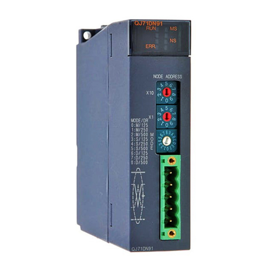
5 SETUP AND PREPARATION MELSEC-Q 5.3 Part Names and Settings This section describes the part names, LED indications, and respective switch settings of the QJ71DN91. Node No. switches Mode switch DeviceNet connector 5 - 5 5 - 5... -
Page 101: Led Indications
MELSEC-Q 5.3.1 LED indications The following explains the names of the LEDs on the QJ71DN91 and their indications in mode 0 to 8. For the LED indications in mode 9 to C, refer to Section 5.4 Hardware Test or 5.6 Communication Test. -
Page 102: Node Number Switches
5 SETUP AND PREPARATION MELSEC-Q 5.3.2 Node number switches The following explains the node number switches of the QJ71DN91 Table 5.2 Node number switches Name Description Node number switch Used to set the node No. of the module. (Factory default: 0) Do not change the node No. -
Page 103: Hardware Test
5 SETUP AND PREPARATION MELSEC-Q 5.4 Hardware Test The hardware test checks whether or not the module operates normally in stand- alone condition. It performs ROM check, RAM check, self-loopback test, etc. Be sure to perform the hardware test before building a system. For the test related to DeviceNet communications, refer to Section 5.6 Communication Test and perform it after wiring. -
Page 104: Wiring
5 SETUP AND PREPARATION MELSEC-Q 5.5 Wiring (1) Connecting a DeviceNet cable The following explains how to connect a DeviceNet cable to the QJ71DN91. V+ (red) CAN_H (white) Shield (drain wire) CAN_L (blue) V- (black) The figure above shows the QJ71DN91's DeviceNet connector. -
Page 105: Communication Test
5 SETUP AND PREPARATION MELSEC-Q 5.6 Communication Test The transmission and reception tests are performed after connecting the QJ71DN91 and other DeviceNet devices with DeviceNet cables. There is no restriction on the node No. setting of the communication target. Execute the test in the following sequence:... -
Page 106: Precautions For Network Power Supply
5 SETUP AND PREPARATION MELSEC-Q 5.7 Precautions for Network Power Supply This section describes the precautions for network power supply. 5.7.1 Network power supply unit position Follow the procedure below to determine the position to install the network power supply unit. Calculate the current consumption of each node on the network. -
Page 107: Network Power Supply Unit Position And Current Capacity Calculation
5 SETUP AND PREPARATION MELSEC-Q 5.7.2 Network power supply unit position and current capacity calculation This section describes where to install the network power supply unit and how to calculate the current capacity. (1) Connecting the network power supply unit to one end of the network When the network is 200m long in total and uses thick cables, the current capacity can be calculated as shown below. - Page 108 5 SETUP AND PREPARATION MELSEC-Q (3) When the network power supply current capacity is insufficient In the case where the network power supply unit is connected to the following network that uses thick cables: Network power supply unit Terminating Terminating resistor resistor Master node...
- Page 109 5 SETUP AND PREPARATION MELSEC-Q (4) When using both trunk and drop lines The current capacity is calculated as shown below when the network power supply unit is connected to a network that has a 200m-long trunk line of thick cables and a 6m-long drop line of a thin cable.
-
Page 110: Utility Package (Gx Configurator-Dn)
Description section (1) The QJ71DN91’s buffer memory is configured for automatic refresh. (2) Values set for auto refresh and stored in the QJ71DN91’s buffer memory are Auto refresh automatically read out when the END instruction is executed in the programmable controller CPU. -
Page 111: Installing And Uninstalling The Utility Package
6 UTILITY PACKAGE (GX Configurator-DN) MELSEC-Q 6.2 Installing and Uninstalling the Utility Package For how to install or uninstall the utility package, refer to "Method of installing the MELSOFT Series" included in the utility package. 6.2.1 Handling precautions The following explains the precautions on using the GX Configurator-DN. (1) For safety Since GX Configurator-DN is add-in software for GX Developer, read "Safety Precautions"... - Page 112 (7) Writing parameters via the network The QJ71DN91 does not support writing of parameters via the network. 6 - 3 6 - 3...
-
Page 113: Operating Environment
6 UTILITY PACKAGE (GX Configurator-DN) MELSEC-Q 6.2.2 Operating environment This section explains the operating environment of the personal computer that runs GX Configurator-DN. Item Description *2*4 Add-in to GX Developer Version 4 (English version) or later Installation (Add-in) target Computer Personal computer compatible with the operating system listed below Refer to the next page "Operating system and performance required for personal computer". - Page 114 6 UTILITY PACKAGE (GX Configurator-DN) MELSEC-Q Operating system and performance required for personal computer Performance required for personal computer Operating system Memory ® ® Windows Pentium 133MHz or more 32MB or more ® ® Windows Pentium 133MHz or more 32MB or more ®...
-
Page 115: Utility Package Operation
6 UTILITY PACKAGE (GX Configurator-DN) MELSEC-Q 6.3 Utility Package Operation 6.3.1 Common utility package operations (1) Control keys Special keys that can be used for operation of the utility package and their applications are shown in the table below. Application Cancels the current entry in a cell. - Page 116 6 UTILITY PACKAGE (GX Configurator-DN) MELSEC-Q (2) Data created with the utility package The following data or files that are created with the utility package can be also handled in GX Developer. Figure 6.1 shows respective data or files are handled in which operation.
- Page 117 Auto refresh setting, or Monitor/Test screen. The text files can be utilized to create user documents. GX Developer/ Disk GX Configurator-DN Project Project Personal computer QCPU QJ71DN91 QJ71DN91 Q25HCPU MODE ERR. ERR. USER NODE ADDRESS A: Intelligent function module parameters B: Flash ROM data.
-
Page 118: Operation Overview
6 UTILITY PACKAGE (GX Configurator-DN) MELSEC-Q 6.3.2 Operation overview GX Developer screen [Tools] - [Intelligent function utility] - [Start] Screen for selecting a target intelligent function module Enter "Start I/O No.", and select "Module type" and "Module model name". Refer to Section 6.3.3. Auto refresh Auto refresh setting screen Refer to Section 6.4. - Page 119 6 UTILITY PACKAGE (GX Configurator-DN) MELSEC-Q [Tools] - [Flash ROM setting] [Online] - [Monitor/Test] Selecting monitor/test module screen Flash ROM setting Select "Module type" Select and "Module model name." Select a module to be monitored/tested. Monitor/Test Flash ROM setting screen Monitor/Test screen Refer to Section 6.6.
-
Page 120: Starting The Intelligent Function Module Utility
6 UTILITY PACKAGE (GX Configurator-DN) MELSEC-Q 6.3.3 Starting the Intelligent function module utility [Operating procedure] Intelligent function module utility is started from GX Developer. [Tools] [Intelligent function utility] [Start] [Setting screen] [Explanation of items] Activation of other screens Following screens can be displayed from the intelligent function module utility screen. - Page 121 6 UTILITY PACKAGE (GX Configurator-DN) MELSEC-Q (3) Menu bar (a) File menu Intelligent function module parameters of the project opened by GX Developer are handled. [Open parameters]: Reads a parameter file. [Close parameters]: Closes the parameter file. If any data are modified, a dialog asking for file saving will appear.
-
Page 122: Auto Refresh
6 UTILITY PACKAGE (GX Configurator-DN) MELSEC-Q 6.4 Auto Refresh [Purpose] Configure the QJ71DN91's buffer memory for automatic refresh. This auto refresh setting eliminates the need for reading and writing by sequence programs. [Operating procedure] "Start I/O No.* " "Module type"... - Page 123 6 UTILITY PACKAGE (GX Configurator-DN) MELSEC-Q [Setting items] Reference Item Buffer memory address (Hex.) section Master Function Communication Status 01B0 Error Information for Master Function 01B1 3.4.3 Bus Error Counter 01B2 Bus Off Counter 01B3 Node Configuration Status 01B4 to 01B7 Node Communication Status, Node Communication Error 01BC to 01C3...
- Page 124 6 UTILITY PACKAGE (GX Configurator-DN) MELSEC-Q Command buttons Creates a file containing the screen data in text file format. Make text file Saves the set data and ends the operation. End setup Cancels the setting and ends the operation. Cancel POINT •...
-
Page 125: Monitoring/Test
6 UTILITY PACKAGE (GX Configurator-DN) MELSEC-Q 6.5 Monitoring/Test [Purpose] Start buffer memory monitoring/testing and I/O signal monitoring/testing from this screen. [Operating procedure] "Select monitor/test module" screen "Start I/O No. " "Module type" "Module model name" Monitor/test * Enter the start I/O No. in hexadecimal. The screen can also be started from System monitor of GX Developer Version 6 or later. - Page 126 6 UTILITY PACKAGE (GX Configurator-DN) MELSEC-Q Reference Item Buffer memory address (Hex.) section X/Y Monitor/Test 6.5.1 Parameter Area Monitor/Test 6.5.2 Save Parameters to Flash ROM 6.5.3 Node Configuration Status Monitor 6.5.4 Node Communication Status Monitor 6.5.5 Node Communication Error Status Monitor 6.5.6 Node Fault Status Monitor 6.5.7...
- Page 127 Enter or select values to be written into the buffer memory for test operation. (2) Command buttons Writes parameters to the flash ROM of the QJ71DN91. Write to module Reads parameters from the flash ROM of the Read from module QJ71DN91.
-
Page 128: X/Y Monitor/Test
6 UTILITY PACKAGE (GX Configurator-DN) MELSEC-Q 6.5.1 X/Y monitor/test [Purpose] Monitor I/O signals and tests output signals. [Operating procedure] Monitor/Test screen X/Y Monitor/Test [Setting screen] [Setting items] Reference Item Buffer memory address (Hex.) section X00: Watchdog Timer Error 3.3.2 (1) 3.3.2 (2) X01: I/O Communicating 3.3.3 (2) -
Page 129: Parameter Area Monitor/Test
6 UTILITY PACKAGE (GX Configurator-DN) MELSEC-Q 6.5.2 Parameter area monitor/test [Purpose] Configure parameters for master function, parameters for slave function, and auto communication start settings. For auto configuration of the parameters for master function, refer to Section 6.5.15. For saving parameters to the flash ROM, refer to Section 6.5.3. [Operating procedure] Monitor/Test screen Param. -
Page 130: Save Parameters To Flash Rom
6 UTILITY PACKAGE (GX Configurator-DN) MELSEC-Q 6.5.3 Save parameters to flash ROM [Purpose] Save parameters to the flash ROM. Follow the instructions shown in the Setting item column. [Operating procedure] Monitor/Test screen Flash ROM Save [Setting screen] [Setting items] Reference Item Buffer memory address (Hex.) section... -
Page 131: Node Configuration Status Monitor
6 UTILITY PACKAGE (GX Configurator-DN) MELSEC-Q 6.5.4 Node configuration status monitor [Purpose] Monitor the parameter setting status of each slave node. [Operating procedure] Monitor/Test screen Config. Status Mon. [Setting screen] [Setting items] Reference Item Buffer memory address (Hex.) section Node 0 to Node 63 01B4 to 01B7 3.4.4 (1) -
Page 132: Node Communication Error Status Monitor
6 UTILITY PACKAGE (GX Configurator-DN) MELSEC-Q 6.5.6 Node communication error status monitor [Purpose] Monitor the I/O communication error status of each slave node. [Operating procedure] Monitor/Test screen Comm. Err. Status Mon. [Setting screen] [Setting items] Reference Item Buffer memory address (Hex.) section Node 0 to Node 63 01C0... -
Page 133: Failed Node Detection Setting
6 UTILITY PACKAGE (GX Configurator-DN) MELSEC-Q 6.5.8 Failed node detection setting [Purpose] Test whether or not to detect a failed node. [Operating procedure] Monitor/Test screen Failed Node Detection Setting [Setting screen] [Setting items] Reference Item Buffer memory address (Hex.) section Node 0 to Node 63 01CC to 01CF... -
Page 134: Message Communication Area Monitor/Test
6 UTILITY PACKAGE (GX Configurator-DN) MELSEC-Q 6.5.9 Message communication area monitor/test [Purpose] Test the message communication area. For the execution timing, refer to Section 3.3.2 (3). [Operating procedure] Monitor/Test screen Msg. Comm. Area [Setting screen] [Setting items] Reference Item Buffer memory address (Hex.) section Message Communication Command 0110... -
Page 135: I/O Address Area Monitor For Master Function
6 UTILITY PACKAGE (GX Configurator-DN) MELSEC-Q 6.5.10 I/O address area monitor for master function [Purpose] Monitor the start address and size (words) for each slave node in Master Function Receive Data (address: 0700 to 07FF ) and Master Function Transmit Data (address: 0900 to 09FF [Operating procedure]... -
Page 136: Master Function Receive Data Monitor
6 UTILITY PACKAGE (GX Configurator-DN) MELSEC-Q 6.5.11 Master function receive data monitor [Purpose] Monitor the data received from each slave node. [Operating procedure] Monitor/Test screen Master Receive Data [Setting screen] [Setting items] Reference Item Buffer memory address (Hex.) section Master Function Receive Data 0700 to 07FF 3.4.6 (1) -
Page 137: Slave Function Receive Data Monitor
6 UTILITY PACKAGE (GX Configurator-DN) MELSEC-Q 6.5.13 Slave function receive data monitor [Purpose] Monitor the data received from the master node. [Operating procedure] Monitor/Test screen Slave Receive Data [Setting screen] [Setting items] Reference Item Buffer memory address (Hex.) section Slave Function Receive Data 0B00 to 0B3F 3.4.10 (1) -
Page 138: Auto Configuration
6 UTILITY PACKAGE (GX Configurator-DN) MELSEC-Q 6.5.15 Auto configuration [Purpose] Using the auto configuration, set the parameters for master function. Follow the instructions shown in the Setting item column. [Operating procedure] Scroll down on the Monitor/Test screen. [Setting screen] [Setting items] Reference Item Buffer memory address (Hex.) -
Page 139: Flash Rom Parameter Clear
6 UTILITY PACKAGE (GX Configurator-DN) MELSEC-Q 6.5.16 Flash ROM parameter clear [Purpose] Clear the parameters from the flash ROM. Follow the instructions shown in the Setting item column. [Operating procedure] Scroll down on the Monitor/Test screen. [Setting screen] [Setting items] Reference Item Buffer memory address (Hex.) -
Page 140: Parameter Backup
6 UTILITY PACKAGE (GX Configurator-DN) MELSEC-Q 6.5.17 Parameter backup [Purpose] Read the parameters saved in the QJ71DN91’s flash ROM, and save them in the personal computer. Or, read the parameters saved in the personal computer, and save them in the QJ71DN91’s flash ROM. -
Page 141: Flash Rom Setting
6 UTILITY PACKAGE (GX Configurator-DN) MELSEC-Q 6.6 Flash ROM Setting [Purpose] Edit the flash ROM settings offline. Edited parameters can be written to the module from the "Parameter Backup" screen under "Monitor/Test". [Operating procedure] Flash ROM setting screen "Module type" "Module model name"... - Page 142 6 UTILITY PACKAGE (GX Configurator-DN) MELSEC-Q [Explanation of items] (1) Items Setting item: Displays parameter names. Setting value: Enter or select values to be set in the flash ROM. (2) Command button Save file Saves the parameters on the hard disk, etc. Load file Reads the parameters saved on the hard disk, etc.
-
Page 143: Programming For Executing The Master Function
7 PROGRAMMING FOR EXECUTING THE MASTER FUNCTION MELSEC-Q 7 PROGRAMMING FOR EXECUTING THE MASTER FUNCTION This chapter explains programming for executing the master function. When applying the program examples introduced in this chapter to the actual system, make sure to examine the applicability and confirm that it will not cause system control problems. - Page 144 7 PROGRAMMING FOR EXECUTING THE MASTER FUNCTION MELSEC-Q When data of multiple words is sent from/received in the buffer memory of the QJ71DN91, data inconsistency may occur. When sending/receiving data of multiple words, use Data consistency dedicated instruction (DNTMRD, DNTMWR, DNTSRD, DNTSWR).
- Page 145 7 PROGRAMMING FOR EXECUTING THE MASTER FUNCTION MELSEC-Q Transmitting node (QJ71DN91 master) Stores transmit data in Master function transmit data area. Transmit Transmit complete Transmit request Master function data flag: 703H flag: 903H transmit data: 900H Sets Transmit request flag.
-
Page 146: System Configuration
(DRT1-OD08) + 16-point input (1794ADN+IB16)* *1: The QJ71DN91 (master node) is installed to slot 0 of the base unit, with the start I/O No. set to "0000 ". *2: The QJ71DN91 (slave node) is installed to slot 1 of the base unit, with the start I/O No. set to "0020... - Page 147 Node No. Node No.2 Communication speed 125kbaud Connection type Polling I/O points 8 output points 3rd slave node (QJ71DN91(slave node)) Item Setting Node number (Node number switches) Node No.4 (04) Communication speed (Mode switch) 125kbaud (Mode 3) Connection type Polling...
- Page 148 8-point input Receive data FROM X100 to X107 I00 to I07 Node No. 1 Input 00 to input 07 QJ71DN91 slave node (node No. 4) FROM Node No. 4 X110 to X14F 8-byte transfer Node No. 3 status Transmit data...
-
Page 149: Parameters For Master Function
7 PROGRAMMING FOR EXECUTING THE MASTER FUNCTION MELSEC-Q 7.3 Parameters for Master Function (1) Setting items The following table lists the parameters for master function, which are set in a program example. For details of the parameters for master function, refer to Section 3.4.5. For setting by auto configuration, refer to (2) in this section. - Page 150 7 PROGRAMMING FOR EXECUTING THE MASTER FUNCTION MELSEC-Q (2) Operation flow of auto configuration The following explains the operation flow in the case of using auto configuration. When using the utility package, refer to Section 7.3.1 (1). When not using the utility package, refer to Section 7.3.2 (1). I/O Communication Request (Y11) I/O Communicating (X01)
- Page 151 7 PROGRAMMING FOR EXECUTING THE MASTER FUNCTION MELSEC-Q (3) Operation flow of parameter saving to flash ROM The following explains the operation flow in the case of saving parameters to the flash ROM. When using the utility package, refer to Section 7.3.1 (3). When not using the utility package, refer to Section 7.3.2 (3).
-
Page 152: Program Example Using The Utility Package
7 PROGRAMMING FOR EXECUTING THE MASTER FUNCTION MELSEC-Q 7.3.1 Program example using the utility package (1) When using auto configuration POINT (1) Pre-determine the slave node settings (e.g. connection type) before executing auto configuration. (2) Check that the power of the slave nodes and the network is on and the wiring is correct. - Page 153 7 PROGRAMMING FOR EXECUTING THE MASTER FUNCTION MELSEC-Q [1. Stop I/O Communication.] Clicking the I/O Comm. Stop button on the [Monitor/Test] screen will display the [1. Stop I/O Communication.] screen. Follow the setting instructions. When the current value for "Y11: I/O Communication Request" is "I/O Comm.
- Page 154 7 PROGRAMMING FOR EXECUTING THE MASTER FUNCTION MELSEC-Q When the current value for "Y17: Request for Saving Parameters to Flash ROM" is "Save Request", set "OFF" for it. Select "OFF" Execute test button Click the Close button. [2. Set Auto Configuration Operation.] Clicking the Operation Setting button on the [Monitor/Test] screen will display the [1.
- Page 155 7 PROGRAMMING FOR EXECUTING THE MASTER FUNCTION MELSEC-Q [3. Execute Auto Configuration.] Clicking the Auto Config button on the [Monitor/Test] screen will display the [3. Execute Auto Configuration.] screen. Follow the setting instructions. Set "Config. Request" for "Y15: Auto Configuration Request". Select "Config.
- Page 156 7 PROGRAMMING FOR EXECUTING THE MASTER FUNCTION MELSEC-Q [4. Confirm Auto-Configured Parameters.] Clicking the Param. Check button on the [Monitor/Test] screen will display the [4. Confirm Auto-Configured Parameters.] screen. Check the parameters for master function. Check that the settings such as node No., connection type, and I/O points are correct.
- Page 157 7 PROGRAMMING FOR EXECUTING THE MASTER FUNCTION MELSEC-Q POINT (1) Slave node settings detected by auto configuration are stored in order of node (2) When changing parameters for master function, set default values in the areas after the parameter-set areas. (Example) When changing the number of slave nodes that can perform I/O communication from 6 to 4, set default values in the areas for 5th and 6th slave nodes.
- Page 158 7 PROGRAMMING FOR EXECUTING THE MASTER FUNCTION MELSEC-Q (2) When setting parameters manually Set the parameters for master function. Clicking the Parameter Area Monitor/Test button on the [Monitor/Test] screen will display the [Parameter Area Monitor/Test] screen. For information on how to display the [Monitor/Test] screen, refer to Section 6.3.
- Page 159 7 PROGRAMMING FOR EXECUTING THE MASTER FUNCTION MELSEC-Q Save parameters to a flash ROM (Refer to (3) in this section.) POINT When changing parameters for master function, set default values in the areas after the parameter-set areas. (Example) When changing the number of slave nodes that can perform I/O communication from 6 to 4, set default values in the areas for 5th and 6th slave nodes.
- Page 160 7 PROGRAMMING FOR EXECUTING THE MASTER FUNCTION MELSEC-Q When saving the parameters to a flash ROM Clicking the Flash ROM Save button on the [Monitor/Test] screen will display the [5. Save Parameters to Flash ROM.] or [Save Parameters to Flash ROM] screen. (The same setting details are displayed on the both screens.) Follow the setting instructions.
- Page 161 7 PROGRAMMING FOR EXECUTING THE MASTER FUNCTION MELSEC-Q Select the parameter saving area. When saving the parameters for master function and the auto communication start setting, set "Master/Auto Comm." for "Parameter Saving Area Selection". Select "Master/Auto Comm. " Execute test button Set "Save Request"...
- Page 162 7 PROGRAMMING FOR EXECUTING THE MASTER FUNCTION MELSEC-Q If parameter check has failed, "Error Occurred" is displayed for "X03: Error Set Signal for Master Function". Check the error code in the current value column of "Error Information for Master Function", and take corrective actions. (Refer to Section 10.2.1.) After completing the parameter saving to the flash ROM, set "OFF"...
- Page 163 7 PROGRAMMING FOR EXECUTING THE MASTER FUNCTION MELSEC-Q When clearing parameters from the flash ROM Clicking the Flash ROM Clear button on the [Monitor/Test] screen will display the [Flash ROM Parameter Clear] screen. Follow the setting instructions. Set "Param. Clear" for "Flash ROM Parameter Clear". Select "Param.
- Page 164 7 PROGRAMMING FOR EXECUTING THE MASTER FUNCTION MELSEC-Q After completion of clearing the flash ROM parameters, set "OFF" for "Request for Saving Parameters to Flash ROM". Select "OFF" Execute test button Click the Close button. 7 - 22 7 - 22...
- Page 165 7 PROGRAMMING FOR EXECUTING THE MASTER FUNCTION MELSEC-Q 7.3.2 Program example not using the utility package When using auto configuration Device list Reference Device Description section Parameter Setting Command for Master Function M300 Auto Configuration Command ― M301 Auto-Configuration Flag I/O Communicating Auto-Configuring Auto Configuration Completion...
- Page 166 7 PROGRAMMING FOR EXECUTING THE MASTER FUNCTION MELSEC-Q When setting parameters manually Device list Reference Device Description section Parameter Setting Command for Master Function I/O Communicating ― I/O Communication Request Parameters for Master Function (for 1st to 4th slave D4 to D35 3.4.5 nodes) Program example...
- Page 167 7 PROGRAMMING FOR EXECUTING THE MASTER FUNCTION MELSEC-Q Parameters for master function [3rd slave node] Node No.= 4, message group = 3 Connection type = Polling Input byte module = 8 Output byte module = 8 Input word module = 0 Output word module = 0 Input double-word module = 0 Output double-word module = 0...
- Page 168 7 PROGRAMMING FOR EXECUTING THE MASTER FUNCTION MELSEC-Q When saving parameters to a flash ROM Device list Reference Device Description section M302 Parameter Saving Command ― M303 Saving Parameters to Flash ROM Flag I/O Communicating Saving Parameters to Flash ROM Parameters Saved to Flash ROM 3.3.2 (6) I/O Communication Request...
-
Page 169: I/O Communication Function
7 PROGRAMMING FOR EXECUTING THE MASTER FUNCTION MELSEC-Q 7.4 I/O Communication Function 7.4.1 Program example using the utility package Device list Reference Device Description section I/O Communication Start Command ― M96 to M111* Node Communication Status 3.4.4 X100 to X10F* 1st slave node: Node No.1 Master Function X110 to X14F*... - Page 170 7 PROGRAMMING FOR EXECUTING THE MASTER FUNCTION MELSEC-Q Writing intelligent function module parameters (Refer to Section 6.3.3.) Write parameters of the intelligent function modules (auto refresh settings) to the CPU module. Perform this operation from the screen for selecting a target intelligent function module.
-
Page 171: Program Example Not Using The Utility Package
7 PROGRAMMING FOR EXECUTING THE MASTER FUNCTION MELSEC-Q 7.4.2 Program example not using the utility package Device list Reference Device Description section I/O Communication Command ― M100 to M115 Node Communication Status 3.4.4 M200 Data consistency dedicated instruction setting status for master function 3.6.16 D100... - Page 172 7 PROGRAMMING FOR EXECUTING THE MASTER FUNCTION MELSEC-Q Program example When Data consistency dedicated instruction (DNTMRD, DNTMWR) is used Setting parameters for master function (See Section 7.3.) I/O communication function Enables Data consistency- dedicated instruction setting for master function. Reads Data consistency- dedicated instruction setting status for master function.
- Page 173 7 PROGRAMMING FOR EXECUTING THE MASTER FUNCTION MELSEC-Q When the FROM/TO instruction is used Setting parameters for master function (See Section 7.3.) I/O communication function Sets initial transmit data values. Set I/O Communication Request to on. Reads node communication status. 1st slave node: Node No.1 Error handling program for node No.1 Input data processing program for node No.1...
-
Page 174: Message Communication Function
7 PROGRAMMING FOR EXECUTING THE MASTER FUNCTION MELSEC-Q 7.5 Message Communication Function This section explains an example of a sequence program created for message communication. 7.5.1 Example of reading message communication data An example program in this section performs Get Attribute to node No.3. For the area enclosed with a dotted line, refer to the manual for the relevant slave node since the class ID, instance ID, and attribute ID are different depending on the actual area and the slave node. - Page 175 7 PROGRAMMING FOR EXECUTING THE MASTER FUNCTION MELSEC-Q Program example Reads master function communication status. Executes Get Attribute if Master Function Comm. Status is C0 or 40 Get Attribute Node No.3, Class ID = 1 Instance ID = 1 Attribute ID = 7 Writes message comm.
-
Page 176: Example Of Writing Message Communication Data
7 PROGRAMMING FOR EXECUTING THE MASTER FUNCTION MELSEC-Q 7.5.2 Example of writing message communication data An example program in this section performs Set Attribute to node No.3. For the area enclosed with a dotted line, refer to the manual for the relevant slave node since the class ID, instance ID, and attribute ID are different depending on the actual area and the slave node. -
Page 177: Obtaining Error Information
7 PROGRAMMING FOR EXECUTING THE MASTER FUNCTION MELSEC-Q 7.6 Obtaining Error Information This section explains an example of a sequence program that obtains the error information for the master function. Device list Reference Device Description section Error Reset Command ― Error Set Signal for Master Function 3.3.2 (4) Error Reset Request for Master Function... -
Page 178: Allocating Transmit/Receive Data Storage Devices For Future Expansion
) is stored in D1000 to D1251, and the FROM or TO instruction is executed using the start buffer memory address of this information and the data length. QJ71DN91 master node Remote I/O (node No. 1) Programmable controller CPU 8-point input... - Page 179 7 PROGRAMMING FOR EXECUTING THE MASTER FUNCTION MELSEC-Q The following explains a sequence program example for this case. Device list Reference Device Description section I/O Communication Start Command ― I/O Communicating 3.3.2 (2) X200 to X23F 1st slave node: Node No.1 X240 to X27F 2nd slave node: Node No.2 Master Function...
-
Page 180: Programming For Executing The Slave Function
8.1 System Configuration The explanation of the programs in this chapter is based on the system shown in Section 7.2. Note that the transmit/receive data of the QJ71DN91 (slave node) are assigned to the following devices. Item Device Receive data... - Page 181 8 PROGRAMMING FOR EXECUTING THE SLAVE FUNCTION MELSEC-Q Operation flow of parameter saving to flash ROM The following explains the operation flow in the case of saving parameters to the flash ROM. When using the utility package, refer to Section 8.2.1 (2). When not using the utility package, refer to Section 8.2.2 (2).
-
Page 182: Program Example Using The Utility Package
8 PROGRAMMING FOR EXECUTING THE SLAVE FUNCTION MELSEC-Q 8.2.1 Program example using the utility package Setting example Setting the parameters for slave function. Clicking the Parameter Area Monitor/Test button on the [Monitor/Test] screen will display the [Parameter Area Monitor/Test] screen. For information on how to display the [Monitor/Test] screen, refer to Section 6.3. - Page 183 8 PROGRAMMING FOR EXECUTING THE SLAVE FUNCTION MELSEC-Q When saving parameters to flash ROM Clicking the Flash ROM Save button on the [Monitor/Test] screen will display the [5. Save Parameters to Flash ROM.] or [Save Parameters to Flash ROM] screen. (The same setting details are displayed on the both screens.) Follow the setting instructions.
- Page 184 8 PROGRAMMING FOR EXECUTING THE SLAVE FUNCTION MELSEC-Q Select the parameter saving area. When saving the parameters for slave function and the auto communication start setting, set "Slave/Auto Comm." for "Parameter Saving Area Selection". Select "Slave/Auto Comm." Execute test button Set "Save Request"...
- Page 185 8 PROGRAMMING FOR EXECUTING THE SLAVE FUNCTION MELSEC-Q If parameter check has failed, "Error Occurred" is displayed for "X08: Error Set Signal for Slave Function". Check the error code in the current value column of "Error Information for Slave Function", and take corrective actions. (Refer to Section 10.2.1.) After completing the parameter saving to the flash ROM, set "OFF"...
- Page 186 8 PROGRAMMING FOR EXECUTING THE SLAVE FUNCTION MELSEC-Q 8.2.2 Program example not using the utility package Setting example Device list Reference Device Description section Parameter Setting Command for Slave Function I/O Communicating — I/O Communication Request Slave Function Receive-Bytes (Input Sizes) Setting Area 3.4.9 Slave Function Transmit-Bytes (Output Sizes) Setting...
- Page 187 8 PROGRAMMING FOR EXECUTING THE SLAVE FUNCTION MELSEC-Q When saving parameters to a flash ROM Device list Reference Device Description section M402 Parameter Saving Command — M403 Saving Parameters to Flash ROM Flag I/O Communicating Saving Parameters to Flash ROM Parameters Saved to Flash ROM 3.3.2 (6) I/O Communication Request...
-
Page 188: I/O Communication Function
8 PROGRAMMING FOR EXECUTING THE SLAVE FUNCTION MELSEC-Q 8.3 I/O Communication Function 8.3.1 Program example using the utility package Device list Reference Device Description section I/O Communication Start Command — I/O Communicating 3.3.3 (2) X200 to X23F Slave Function Receive Data 3.4.10 I/O Communication Request 3.3.3 (2) - Page 189 8 PROGRAMMING FOR EXECUTING THE SLAVE FUNCTION MELSEC-Q Program example Setting parameters for slave function (See Section 8.2.) I/O communication function Sets I/O Communication Request to on. Input data processing program Output data processing program POINT To ensure consistency of transmit/receive data of multiple words, take a measure such as providing a handshake area at the end of transmit/receive data to check the data transfer.
-
Page 190: Program Example Using The Utility Package
8 PROGRAMMING FOR EXECUTING THE SLAVE FUNCTION MELSEC-Q 8.3.2 Program example not using the utility package Device list Reference Device Description section I/O Communication Start Command — M250 Data consistency dedicated instruction setting status for slave function 3.6.16 D150 Data consistency dedicated instruction setting for slave function I/O Communicating 3.3.3 (2) - Page 191 8 PROGRAMMING FOR EXECUTING THE SLAVE FUNCTION MELSEC-Q When the FROM/TO instruction is used Setting parameters for slave function (See Section 8.2.) I/O communication function Sets initial transmit data values. Sets I/O Communication Request to on. Reads receive data. Input data processing program Output data processing program Writes transmit data.
-
Page 192: Obtaining Error Information
8 PROGRAMMING FOR EXECUTING THE SLAVE FUNCTION MELSEC-Q 8.4 Obtaining Error Information This section explains an example of a sequence program that obtains the error information for the slave function. Device list Reference Device Description section Error Reset Command — Error Set Signal for Slave Function 3.3.3 (4) Error Reset Request for Slave Function... - Page 193 9 DEDICATED INSTRUCTIONS Dedicated instructions enable easy programming to use the functions of an intelligent function module. This chapter explains dedicated instructions available for the QJ71DN91. (1) List of dedicated instructions Dedicated instructions available for the QJ71DN91 are shown below.
-
Page 194: Precautions
Compatible module versions Use the modules with the following serial numbers. • The QJ71DN91 with the first five digits of the serial number is "13042" or later • The QCPU with the first five digits of the serial number is "02092" or later... -
Page 195: G.dntmrd
This program reads 4-point data from the Master Function Receive Data (address: 0700 ~) area of the QJ71DN91 to D0 - D3 by turning on the following I/O signal and buffer memory area. (In this example, the QJ71DN91 is mounted on the slot 0 of the base unit with "0000 "... -
Page 196: G.dntmwr
09FF ) area of the QJ71DN91 by turning on the following I/O signal and buffer memory area. (In this example, the QJ71DN91 is mounted on the slot 0 of the base unit with "0000 " set to start I/O No.) •... -
Page 197: G.dntsrd
This program reads 4-point data from the Slave Function Receive Data (address: 0B00 ~) area of the QJ71DN91 to D0 - D3 by turning on the following I/O signal and buffer memory area. (In this example, the QJ71DN91 is mounted on the slot 0 of the base unit with "0000 "... -
Page 198: G.dntswr
0C3F ) area of the QJ71DN91 by turning on the following I/O signal and buffer memory area. (In this example, the QJ71DN91 is mounted on the slot 0 of the base unit with "0000 " set to start I/O No.) •... -
Page 199: Troubleshooting
10 TROUBLESHOOTING MELSEC-Q 10 TROUBLESHOOTING This chapter describes the errors that may occur while using the QJ71DN91 as well as their troubleshooting procedures. This chapter contains the following information: Section 10.1 Problem Identification Troubleshooting procedures are shown according to symptoms. -
Page 200: Problem Identification
10 TROUBLESHOOTING MELSEC-Q 10.1 Problem Identification This section explains checking procedures and actions to be taken when a problem occurs. 10.1.1 Checking the LEDs Problem occurred Set Mode switch in range of 0 to 8 Mode switch set in 0 to 8? and reset. -
Page 201: When Unable To Communicate With All Slave Nodes (When Using Master Function)
Terminating resistors connected? Connect terminating resistors. Is there a slave node having same node No. as Eliminate node No. duplication. QJ71DN91? Have the parameters been written? Are the parameters matched with hardware configuration of the Configure and write correct parameters. -
Page 202: When Unable To Communicate With A Specific Slave Node (When Using Master Function)
10 TROUBLESHOOTING MELSEC-Q 10.1.3 When unable to communicate with a specific slave node (when using master function) Unable to communicate with a specific slave node. (NS LED is flashing red.) Power on the slave node. Is the slave node powered on? Is DeviceNet cable connected to the slave no Connect DeviceNet cable securely. -
Page 203: When Unable To Communicate With Master Node (When Using Slave Function)
Mode switch set in 3 to 8? Set Mode switch in range of 3 to 8 and reset. Is DeviceNet Connect DeviceNet cable securely. cable connected to QJ71DN91's connector securely Is network power supply on? Turn on the network power supply. -
Page 204: Troubleshooting For Other Cases
• Is the network powered on? powered up and the wiring is correct. • Is the wiring correct? • If the target slave node is the QJ71DN91, When the auto communication start setting is check if "Start" is set in Auto Communication... - Page 205 10 TROUBLESHOOTING MELSEC-Q Symptom Check Action • Set "Not start" in Auto Communication Start Setting (address: 0631 ), and save the After power-up, I/O • Is "Start" set in Auto Communication Start parameters to a flash ROM. communication starts Setting (address: 0631 •...
-
Page 206: Error Codes
• Set the node No. within the range of 0 to The node No. (MAC ID) value is out of QJ71DN91 range. • Set the mode switch to any other than D The mode switch value is out of range. - Page 207 Zero (0) is set for both the input and • Set the input and output points according QJ71DN91 output points of a slave node. to the slave node specifications. The low byte of the slave node No. in the QJ71DN91 •...
- Page 208 DNTMWR is executed in every scan. DNTMWR was not executed for three • When not using Data consistency sequence scans although "Data QJ71DN91 dedicated instruction, disable "Data consistency dedicated instruction setting consistency dedicated instruction setting for master function" is enabled.
- Page 209 • Check the slave node manual, and prevent any data of the function not Response data of the function that is not supported by the QJ71DN91 from being QJ71DN91 supported by the QJ71DN91 was sent from the slave node.
- Page 210 The number of bytes received by polling • Set the master node’s I/O points that QJ71DN91 is greater than the max. number of match the settings of the QJ71DN91. receive points. 10 - 12 10 - 12...
-
Page 211: Execution Error Codes Of Message Communication (For The Master Function Only)
When reading communication error information Error Detected code Description Action (Dec.) QJ71DN91 The specified slave node No. is other than 0 to 63. • Specify a slave node No. within the range of 0 to 63. When getting/setting attribute, or resetting Error Detected code... - Page 212 • Check the entire network and slave node states for QJ71DN91 Slave node did not respond. any fault such as slave node failure, or disconnection of a terminating resistor.
- Page 213 Description Action (Dec.) • Check whether the parameter value for the message QJ71DN91 Failed to open a message connection. group is set correctly or not. • Verify that the transmit message can be responded by Slave node The response data length is too long.
-
Page 214: General Devicenet Error Codes Of Message Communication (For The Master Function Only)
10 TROUBLESHOOTING MELSEC-Q 10.2.3 General DeviceNet error codes of message communication (for the master function only) A general DeviceNet error code is stored in Message Communication Data (address: 0133 Read it when Message Communication Completion signal (X02) is set to on, and check the error details. -
Page 215: Checking The Qj71Dn91 Status By System Monitor In Gx Developer
10 TROUBLESHOOTING MELSEC-Q 10.3 Checking the QJ71DN91 Status by System Monitor in GX Developer Error codes and LED status can be checked by selecting the detailed information of the QJ71DN91 from System monitor of GX Developer. Operation procedure Select "Diagnostics" – "System monitor", choose a module, and then "Module's Detailed Information"... - Page 216 10 TROUBLESHOOTING MELSEC-Q H/W LED Information The LED status of the QJ71DN91 is displayed. (0: OFF, 1: ON) ERR: Indicates the "ERR" LED status. MS RED: Indicates the "MS (red)" LED status. MS GREEN: Indicates the "MS (green)" LED status.
-
Page 217: Appendixes
APPENDIXES MELSEC-Q APPENDIXES Appendix 1 External Dimensions The external dimensions of the QJ71DN91 are shown below. 27.4 (Unit: mm) App - 1 App - 1... -
Page 218: Appendix 2 Functional Upgrade Of The Qj71Dn91
APPENDIXES MELSEC-Q Appendix 2 Functional Upgrade of the QJ71DN91 The table below lists new functions of the QJ71DN91 and serial number and software version of the products that support each function. First 5 digits of serial Software version Reference number... -
Page 219: Appendix 3.2 I/O Signals
APPENDIXES MELSEC-Q Appendix 3.2 I/O signals The following table lists differences in I/O signals between the QJ71DN91 and the AJ71DN91/A1SJ71DN91. Precautions when replacing the Model QJ71DN91 AJ71DN91/A1SJ71DN91 AJ71DN91/A1SJ71DN91 with the Signal QJ71DN91 I/O Communicating Refreshing The module operation using this I/O... - Page 220 APPENDIXES MELSEC-Q (1) Operation of the module using I/O signals The QJ71DN91 and the AJ71DN91/A1SJ71DN91 differ in the following: • Timing of I/O communication start and I/O data communication • Operation after parameters are saved normally Operation of the QJ71DN91...
-
Page 221: Appendix 3.3 Buffer Memory
APPENDIXES MELSEC-Q Appendix 3.3 Buffer memory The following table lists differences in buffer memory between the QJ71DN91 and the AJ71DN91/A1SJ71DN91. Model Precautions when replacing the Buffer memory address QJ71DN91 AJ71DN91/A1SJ71DN91 AJ71DN91/A1SJ71DN91 with the QJ71DN91 Hex. Dec. Replace the address of Input data with... -
Page 222: Appendix 3.4 Parameters For Master Function
01DD EXPECTED PACKET RATE Default value: 200ms Default value: 500ms Appendix 3.5 Hardware The following table lists differences in hardware between the QJ71DN91 and the AJ71DN91/A1SJ71DN91. Model Precautions when replacing the AJ71DN91/A1SJ71DN91 with QJ71DN91 AJ71DN91/A1SJ71DN91 Signal the QJ71DN91 L.RUN... -
Page 223: Appendix 4 The Comparison Of Operation Between Gx Configurator-Dn And Gx Works2
4) Click the Execute button. Follow the procedure below when performing flash ROM setting. Flash ROM setting is performed on the 1) Open the setting window data of QJ71DN91. Flash ROM setting Flash ROM window. (Refer to Section 2) Select [Tool] →[Flash ROM Operation]. -
Page 224: Appendix 5 How To Use The Qj71Dn91 In System Of Melsec Iq-R Series
MELSEC-Q Appendix 5 How to Use the QJ71DN91 in System of MELSEC iQ-R Series By using RQ extension base unit, the QJ71DN91 can be used in the system of MELSEC iQ-R series. For details, refer to the MELSEC iQ-R Module Configuration Manual. -
Page 225: Appendix 6 Parameter Setting Sheet (For The Master Function)
APPENDIXES MELSEC-Q Appendix 6 Parameter Setting Sheet (For the Master Function) Buffer memory Item Description Set value address (Hex.) Specify a value to make the link scan time constant. 01D7 Constant scan (Setting range: 0 to 65535ms (FFFF th slave node] Buffer memory Item Description... -
Page 226: Appendix 7 Parameter Setting Sheet (For The Slave Function)
APPENDIXES MELSEC-Q Appendix 7 Parameter Setting Sheet (For the Slave Function) Buffer memory Item Description Set value address (Hex.) Slave function receive-bytes Set a size of I/O data that can be received for the slave function. 060E (input size) setting area (Setting range: 0 to 128 bytes, Default: 8 bytes) Slave function transmit-bytes Set a size of I/O data that can be sent for the slave function. -
Page 227: Appendix 8 List Of Communication Parameters Of Slave Nodes From Various Manufactures
UCMM manufacturer type Timeout group Rate Time Output Input Output Input Output Input Action DeviceNet 200ms Timeout 10ms QJ71DN91 master/slave Polling (H1) (K201) (H1) (H0) Mitsubishi module Electric A500 Series Corporation inverter 1000ms Timeout 10ms FR-A5ND Polling (H1) DeviceNet (K1001) -
Page 228: Appendix 9 Eds File Of The Qj71Dn91
APPENDIXES MELSEC-Q Appendix 9 EDS File of the QJ71DN91 The following shows the EDS file of the QJ71DN91. $ Mitsubishi Master/Slave EDS file $ File Description Section [File] DescText="QJ71DN91 EDS file"; CreateDate=08-28-2000; $ created CreateTime=12:00:00; ModDate=08-28-2000; $ last change ModTime=12:00:00;... -
Page 229: Index
INDEX Expected packet rate ........3-33 External dimensions ........App-1 Add configuration .......... 3-34 All configuration ..........3-34 Auto-configuring (X14) ........3-12 Failed node detection setting ......3-30 Auto configuration ......... A-13 Flash ROM setting ......... 6-32 Auto configuration completion (X15) .... 3-12 Functions of the utility package ....... - Page 230 Message communication error signal (X05) Slave function (I/O communication function) ................. 3-8 ..............4-12, 8-9 Message communication function ..4-9, 7-32 Slave function communication status .... 3-39 Message communication request (Y12) ..3-8 Slave function receive data ......3-41 Slave function receive-bytes setting area ..3-40 Slave function transmit data ......
- Page 231 WARRANTY Please confirm the following product warranty details before using this product. 1. Gratis Warranty Term and Gratis Warranty Range If any faults or defects (hereinafter "Failure") found to be the responsibility of Mitsubishi occurs during use of the product within the gratis warranty term, the product shall be repaired at no cost via the sales representative or Mitsubishi Service Company.
- Page 232 Microsoft, Windows, Windows Vista, Windows NT, Windows XP, Windows Server, Visio, Excel, PowerPoint, Visual Basic, Visual C++, and Access are either registered trademarks or trademarks of Microsoft Corporation in the United States, Japan, and other countries. Intel, Pentium, and Celeron are either registered trademarks or trademarks of Intel Corporation in the United States and other countries.
- Page 234 SH(NA)-080143-M(1409)MEE MODEL: QJ71DN91-U-S-E MODEL CODE: 13JR32 HEAD OFFICE : TOKYO BUILDING, 2-7-3 MARUNOUCHI, CHIYODA-KU, TOKYO 100-8310, JAPAN NAGOYA WORKS : 1-14 , YADA-MINAMI 5-CHOME , HIGASHI-KU, NAGOYA , JAPAN When exported from Japan, this manual does not require application to the Ministry of Economy, Trade and Industry for service transaction permission.