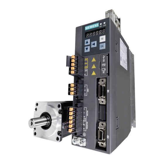
Siemens SIMOTICS S-1FL6 Operating Instructions Manual
Sinamics / simotics
Hide thumbs
Also See for SIMOTICS S-1FL6:
- Compact operating instructions (119 pages) ,
- Installation manual (10 pages) ,
- Operating instructions manual (432 pages)
Table of Contents
Advertisement
Quick Links
SINAMICS/SIMOTICS
SINAMICS V90, SIMOTICS S-1FL6
Operating Instructions
PROFINET (PN) interface
09/2016
A5E37208830-002
___________________
Preface
Fundamental safety
___________________
instructions
___________________
General information
___________________
Mounting
___________________
Connecting
___________________
Commissioning
___________________
Basic operator panel (BOP)
___________________
Control functions
___________________
PROFINET communication
___________________
Safety integrated function
___________________
Tuning
___________________
Parameters
___________________
Diagnostics
___________________
Appendix
1
2
3
4
5
6
7
8
9
10
11
12
A
Advertisement
Table of Contents

Related Manuals for Siemens SIMOTICS S-1FL6


Summary of Contents for Siemens SIMOTICS S-1FL6
- Page 1 ___________________ Preface Fundamental safety ___________________ instructions ___________________ SINAMICS/SIMOTICS General information ___________________ Mounting SINAMICS V90, SIMOTICS S-1FL6 ___________________ Connecting ___________________ Commissioning Operating Instructions ___________________ Basic operator panel (BOP) ___________________ Control functions ___________________ PROFINET communication ___________________ Safety integrated function ___________________ Tuning ___________________...
- Page 2 Note the following: WARNING Siemens products may only be used for the applications described in the catalog and in the relevant technical documentation. If products and components from other manufacturers are used, these must be recommended or approved by Siemens. Proper transport, storage, installation, assembly, commissioning, operation and maintenance are required to ensure that the products operate safely and without any problems.
-
Page 3: Preface
Describes how to install, connect, operate, and perform basic commissioning of the SINAMICS V90 PN servo sys- tem. SIMOTICS S-1FL6 Servo Motors Installation Guide Describes how to install the SMOTICS S-1FL6 servo motor and relevant safety notices. SINAMICS V90 Servo Drives Information Guide Describes how to find all the SINAMICS V90 documents from the website and relevant safety notices. - Page 4 This document contains recommendations relating to third-party products. Siemens accepts the fundamental suitability of these third-party products. You can use equivalent products from other manufacturers. Siemens does not accept any warranty for the properties of third-party products. SINAMICS V90, SIMOTICS S-1FL6 Operating Instructions, 09/2016, A5E37208830-002...
-
Page 5: Table Of Contents
Motor power - U, V, W ......................78 Control/status interface - X8 ....................80 4.3.1 Digital inputs/outputs (DIs/Dos) ....................81 4.3.1.1 DIs ............................81 4.3.1.2 DOs ............................83 4.3.2 Standard application wiring (factory setting) ................84 SINAMICS V90, SIMOTICS S-1FL6 Operating Instructions, 09/2016, A5E37208830-002... - Page 6 Setting the mechanical system .................... 133 7.2.2 Configuring the linear/modular axis ..................134 7.2.3 Backlash compensation ....................... 135 7.2.4 Over-travel ........................... 136 7.2.5 Software position limit ......................137 7.2.6 Speed limit ........................... 138 SINAMICS V90, SIMOTICS S-1FL6 Operating Instructions, 09/2016, A5E37208830-002...
- Page 7 System features ........................190 9.3.1 STO functional safety data ....................190 9.3.2 Certification ........................... 190 9.3.3 Safety instructions ......................... 191 9.3.4 Probability of failure of the safety function ................192 9.3.5 Response time ........................192 SINAMICS V90, SIMOTICS S-1FL6 Operating Instructions, 09/2016, A5E37208830-002...
- Page 8 Assembly of cable connectors on the motor side ..............286 Motor selection ........................290 A.3.1 Selection procedure ......................290 A.3.2 Parameter description ......................291 A.3.3 Selection examples ......................293 Replacing fans ........................294 Index ..............................295 SINAMICS V90, SIMOTICS S-1FL6 Operating Instructions, 09/2016, A5E37208830-002...
-
Page 9: Fundamental Safety Instructions
Touching live components can result in death or severe injury. • Only use power supplies that provide SELV (Safety Extra Low Voltage) or PELV- (Protective Extra Low Voltage) output voltages for all connections and terminals of the electronics modules. SINAMICS V90, SIMOTICS S-1FL6 Operating Instructions, 09/2016, A5E37208830-002... - Page 10 • Tighten all power connections with the specified tightening torques, e.g. line supply connection, motor connection, DC link connections. • Check all power connections at regular intervals. This applies in particular after transport. SINAMICS V90, SIMOTICS S-1FL6 Operating Instructions, 09/2016, A5E37208830-002...
- Page 11 • Check that the warning labels are complete based on the documentation. • Attach any missing warning labels to the components, in the national language if necessary. • Replace illegible warning labels. SINAMICS V90, SIMOTICS S-1FL6 Operating Instructions, 09/2016, A5E37208830-002...
- Page 12 As a result of incorrect or changed parameterization, machines can malfunction, which in turn can lead to injuries or death. • Protect the parameterization (parameter assignments) against unauthorized access. • Respond to possible malfunctions by applying suitable measures (e.g. EMERGENCY STOP or EMERGENCY OFF). SINAMICS V90, SIMOTICS S-1FL6 Operating Instructions, 09/2016, A5E37208830-002...
- Page 13 • Operate the motor according to the relevant specifications. • Only operate the motors in conjunction with effective temperature monitoring. • Immediately switch off the motor if excessively high temperatures occur. SINAMICS V90, SIMOTICS S-1FL6 Operating Instructions, 09/2016, A5E37208830-002...
-
Page 14: Handling Electrostatic Sensitive Devices (Esd)
– Wearing ESD shoes or ESD grounding straps in ESD areas with conductive flooring • Only place electronic components, modules or devices on conductive surfaces (table with ESD surface, conductive ESD foam, ESD packaging, ESD transport container). SINAMICS V90, SIMOTICS S-1FL6 Operating Instructions, 09/2016, A5E37208830-002... -
Page 15: Industrial Security
Siemens recommends strongly that you regularly check for product updates. For the secure operation of Siemens products and solutions, it is necessary to take suitable preventive action (e.g. cell protection concept) and integrate each component into a holistic, state-of-the-art industrial security concept. -
Page 16: Residual Risks Of Power Drive Systems
5. Release of environmental pollutants or emissions as a result of improper operation of the system and/or failure to dispose of components safely and correctly For more information about the residual risks of the drive system components, see the relevant sections in the technical user documentation. SINAMICS V90, SIMOTICS S-1FL6 Operating Instructions, 09/2016, A5E37208830-002... -
Page 17: General Information
95 x 170 x 195 6SL3210-5FB11-0UF1 three-phase, 200 V 6SL3210-5FB11-5UF0 6SL3210-5FB12-0UF0 Connectors For FSB 6SL3200-0WT02-0AA0 For FSC and FSD 6SL3200-0WT03-0AA0 Shielding plate For FSB For FSC and FSD User documentation Information Guide English-Chinese bilingual version SINAMICS V90, SIMOTICS S-1FL6 Operating Instructions, 09/2016, A5E37208830-002... - Page 18 * You can obtain the connectors for SINAMICS V90 PN 400V servo drives of FSB and FSC from the connector kits for SINAMICS V90 PN 400V servo drives of FSAA or FSA. SINAMICS V90, SIMOTICS S-1FL6 Operating Instructions, 09/2016, A5E37208830-002...
- Page 19 2.1 Deliverables Drive rating plate (example) ① ⑤ Drive name Order number ② ⑥ Power input MAC address ③ ⑦ Power output Product serial number ④ ⑧ Rated motor power Part number SINAMICS V90, SIMOTICS S-1FL6 Operating Instructions, 09/2016, A5E37208830-002...
-
Page 20: Motor Components
General information 2.1 Deliverables 2.1.2 Motor components Components in the SIMOTICS S-1FL6 low inertia motor package Component Illustration Rated power (kW) Shaft height (mm) Order number SIMOTICS S-1FL6, 0.05/0.1 1FL6022-2AF21-1❑❑1 low inertia 1FL6024-2AF21-1❑❑1 0.2/0.4 1FL6032-2AF21-1❑❑1 1FL6034-2AF21-1❑❑1 0.75/1.0 1FL6042-2AF21-1❑❑1 1FL6044-2AF21-1❑❑1 1.5/2.0 1FL6052-2AF21-0❑❑1... - Page 21 Thermal class Motor ID ④ ⑩ ⑯ Rated torque Degree of protection Weight ⑤ ⑪ ⑰ Stall torque Motor operating mode Maximum speed ⑥ ⑫ ⑱ Rated voltage Stall current Rated speed SINAMICS V90, SIMOTICS S-1FL6 Operating Instructions, 09/2016, A5E37208830-002...
-
Page 22: Device Combination
General information 2.2 Device combination Device combination V90 PN 200 V servo system SIMOTICS S-1FL6 low inertia servo motors SINAMICS V90 PN MOTION-CONNECT 300 pre-assembled 200 V servo drives cables Power Brake Encoder cable cable cable Rated Rated Rated Shaft... - Page 23 General information 2.2 Device combination V90 PN 400 V servo system SIMOTICS S-1FL6 high inertia servo motors SINAMICS V90 PN MOTION-CONNECT 300 pre-assembled 400 V servo drives cables Power Brake Encoder cable cable cable Rated Rated Rated Shaft Order number...
-
Page 24: Product Overview
General information 2.3 Product overview Product overview SINAMICS V90 PN servo drives ● SINAMICS V90 PN 200V variant FSC and FSD SINAMICS V90, SIMOTICS S-1FL6 Operating Instructions, 09/2016, A5E37208830-002... - Page 25 General information 2.3 Product overview ● SINAMICS V90 PN 400V variant FSAA and FSA FSB and FSC SINAMICS V90, SIMOTICS S-1FL6 Operating Instructions, 09/2016, A5E37208830-002...
- Page 26 General information 2.3 Product overview SIMOTICS S-1FL6 servo motors ● Low inertia motors Shaft height: 20 mm, 30 mm, and 40 mm Shaft height: 50 mm SINAMICS V90, SIMOTICS S-1FL6 Operating Instructions, 09/2016, A5E37208830-002...
-
Page 27: Accessories
5BK02-1AF0 10 m 5BK02-1BA0 20 m 5BK02-1CA0 Encod- 0SB14 Incre- 2CT20-1AD0 Incremen- 0SL12 er con- cre- tal encod- 2CT20-1AF0 nector menta 10 m 2CT20-1BA0 l en- connector coder 20 m 2CT20-1CA0 cable SINAMICS V90, SIMOTICS S-1FL6 Operating Instructions, 09/2016, A5E37208830-002... - Page 28 7 m * 2DB10-1AH0 coder cable 10 m 2DB10-1BA0 15 m * 2DB10-1BF0 20 m 2DB10-1CA0 * The cables with lengths of 7 m and 15 m are only supplied for high inertia motors. SINAMICS V90, SIMOTICS S-1FL6 Operating Instructions, 09/2016, A5E37208830-002...
- Page 29 National Electrical Code and any additional local codes. Refer to the table below for the selection of fuses, type-E combination motor controllers, and circuit breakers: SINAMICS V90, SIMOTICS S-1FL6 Operating Instructions, 09/2016, A5E37208830-002...
- Page 30 3RV 2021-4BA10 3NA3 810-6 (25 A) 25 A 20 to 25 380/480 3RV 2021-4DA10 The above types for Type-E combination motor controllers are listed in compliance with both CE and UL/cUL standards. SINAMICS V90, SIMOTICS S-1FL6 Operating Instructions, 09/2016, A5E37208830-002...
- Page 31 When the motor works in a fast round-trip process, the voltage of the line supply increases. The braking resistor starts to work if the voltage reaches the set threshold. The temperature of the heat sink increases (>100 °C) when the braking resistor is working. If alarms A52901 SINAMICS V90, SIMOTICS S-1FL6 Operating Instructions, 09/2016, A5E37208830-002...
- Page 32 189.6 Filter Siemens recommends you to use a line filter to protect the system from high frequency noise. The line filter restricts the conductive interference emitted from the SINAMICS V90 PN to the permissible values. The SINAMICS V90 PN drives with these external line filters have been tested in accordance with the emission requirements of the Category C2 environment.
- Page 33 General information 2.4 Accessories Outline dimensions (mm) Filter used on the single phase power network Filter used on the three phase power network Rated current (A) ø1 SINAMICS V90, SIMOTICS S-1FL6 Operating Instructions, 09/2016, A5E37208830-002...
- Page 34 Noise frequency 0.15 (MHz) CM (dB) DM (dB) Rated current 18 A Noise frequency 0.15 (MHz) CM (dB) DM (dB) Rated current 20 A Noise frequency 0.15 (MHz) CM (dB) DM (dB) SINAMICS V90, SIMOTICS S-1FL6 Operating Instructions, 09/2016, A5E37208830-002...
- Page 35 Wire gauge Stripping length 200 V current (A) torque (Nm) (AWG) L (mm) 6SL3210-5FB10-1UF0 18 Cross-tip (M4 22 to 20 screw) 6SL3210-5FB10-2UF0 22 to 20 6SL3210-5FB10-4UF1 18 to 16 6SL3210-5FB10-8UF0 14 to 12 SINAMICS V90, SIMOTICS S-1FL6 Operating Instructions, 09/2016, A5E37208830-002...
- Page 36 18 to 17 6SL3210-5FE11-0UF0 17 to 16 6SL3210-5FE11-5UF0 Cross-tip (M4 15 to 14 screw) 6SL3210-5FE12-0UF0 13 to 12 6SL3210-5FE13-5UF0 Cross-tip (M4 11 to 10 screw) 6SL3210-5FE15-0UF0 10 to 9 6SL3210-5FE17-0UF0 10 to 9 SINAMICS V90, SIMOTICS S-1FL6 Operating Instructions, 09/2016, A5E37208830-002...
-
Page 37: Function List
Torque limit (Page 156) Limits motor torque through internal torque limit commands EPOS, S (two groups) Basic operator panel (BOP) Displays servo status on a 6-digit 7-segment LED display EPOS, S (Page 111) SINAMICS V90, SIMOTICS S-1FL6 Operating Instructions, 09/2016, A5E37208830-002... -
Page 38: Technical Data
Set through a parameter or the analog input command (0 VDC to +10 VDC/max. torque) Environ- Surrounding air Opera- 0 °C to 45 °C: without power derating mental temperature tion 45 °C to 55 °C: with power derating conditions SINAMICS V90, SIMOTICS S-1FL6 Operating Instructions, 09/2016, A5E37208830-002... - Page 39 V90 PN 400 V servo drive has an overvoltage threshold of 820 VDC and an undervoltage threshold of 320 VDC. SINAMICS V90 PN does not support motor overtemperature protection. Motor overtemperature is calculated by I t and protected by the output current from the drive. SINAMICS V90, SIMOTICS S-1FL6 Operating Instructions, 09/2016, A5E37208830-002...
- Page 40 50 x 170 x 170 80 x 170 95 x 170 x 195 design H x D, mm) x 195 Weight (kg) 1.25 1.95 The values here are calculated at rated load. SINAMICS V90, SIMOTICS S-1FL6 Operating Instructions, 09/2016, A5E37208830-002...
- Page 41 80 x 180 x 200 100 x 180 x 220 140 x 260 x 240 design H x D, mm) 180 x Weight (kg) 5.75 The values here are calculated at rated load. SINAMICS V90, SIMOTICS S-1FL6 Operating Instructions, 09/2016, A5E37208830-002...
-
Page 42: Technical Data - Servo Motors
20,000 to 30,000 hours of service time. Even if the time is not reached, the bearing must be replaced when unusual noise, vibration, or faults are found. Specific technical data SIMOTICS S-1FL6, low inertia servo motor Order No. 1FL60... Rated power [kW] 0.05... - Page 43 This lifetime is only for reference. When a motor keeps running at 80% rated value and the surrounding temperature is 30 °C, the encoder lifetime can be ensured. Note The data of rated torque, rated power, maximum torque, and armature resistance in the above table allows a tolerance of 10%. SINAMICS V90, SIMOTICS S-1FL6 Operating Instructions, 09/2016, A5E37208830-002...
- Page 44 General information 2.6 Technical data Torque-Speed characteristics SINAMICS V90, SIMOTICS S-1FL6 Operating Instructions, 09/2016, A5E37208830-002...
- Page 45 • The feature in short-term operating area varies with power supply voltages. • The continuous operating area becomes smaller and the voltage consumptions on the cables grow larger when the cables in the major loop exceed 20 m. Permissible radial and axial forces SINAMICS V90, SIMOTICS S-1FL6 Operating Instructions, 09/2016, A5E37208830-002...
- Page 46 General information 2.6 Technical data SIMOTICS S-1FL6, high inertia servo motor Order No. 1FL60... Rated power [kW] 0.40 0.75 0.75 1.00 1.50 1.75 2.00 Rated torque [Nm] 1.27 2.39 3.58 4.78 7.16 8.36 9.55 11.9 16.7 23.9 33.4 Maximum torque [Nm] 10.7...
- Page 47 0.89 0.84 2000 1.00 0.94 0.90 0.86 0.82 2500 0.96 0.90 0.86 0.83 0.78 3000 0.92 0.86 0.82 0.79 0.75 3500 0.88 0.82 0.79 0.75 0.71 4000 0.82 0.77 0.74 0.71 0.67 SINAMICS V90, SIMOTICS S-1FL6 Operating Instructions, 09/2016, A5E37208830-002...
- Page 48 General information 2.6 Technical data Torque-Speed characteristics SINAMICS V90, SIMOTICS S-1FL6 Operating Instructions, 09/2016, A5E37208830-002...
- Page 49 20 meters. • For 1FL6096 motors, the maximum speed can be ensured when the line supply voltage is higher than 380V. Permissible radial and axial forces SINAMICS V90, SIMOTICS S-1FL6 Operating Instructions, 09/2016, A5E37208830-002...
-
Page 50: Technical Data - Cables
Cable used for 200 V variant servo drive + low inertia motor of 1.5 kW to 2 kW, and for 400 V variant servo drive + high inertia motor 0.4 kW to 7 kW SINAMICS V90, SIMOTICS S-1FL6 Operating Instructions, 09/2016, A5E37208830-002... -
Page 51: Address Of Ce-Authorized Manufacturer
Maximum acceleration 3 m/s , maximum speed 40 m/min: 1000000 2.6.4 Address of CE-authorized manufacturer The address of CE-authorized manufacturer is as follows: Siemens AG Digital Factory Motion Control Frauenauracher Straße 80 DE-91056 Erlangen Germany SINAMICS V90, SIMOTICS S-1FL6 Operating Instructions, 09/2016, A5E37208830-002... - Page 52 General information 2.6 Technical data SINAMICS V90, SIMOTICS S-1FL6 Operating Instructions, 09/2016, A5E37208830-002...
-
Page 53: Mounting
During operation and for a short time after switching-off the drive, the surfaces of the drive can reach a high temperature. Avoid coming into direct contact with the drive surface. For mounting conditions, see Technical data - servo drives (Page 38). SINAMICS V90, SIMOTICS S-1FL6 Operating Instructions, 09/2016, A5E37208830-002... -
Page 54: Mounting Orientation And Clearance
10 mm. In this case, the minimum mounting clearance should not be less than 5 mm. • The surrounding temperature is 45 °C to 55 °C. In this case, the minimum mounting clearance should not be less than 20 mm. SINAMICS V90, SIMOTICS S-1FL6 Operating Instructions, 09/2016, A5E37208830-002... -
Page 55: Drill Patterns And Outline Dimensions
Mounting 3.1 Mounting the drive 3.1.2 Drill patterns and outline dimensions SINAMICS V90 PN 200V variant (unit: mm) SINAMICS V90, SIMOTICS S-1FL6 Operating Instructions, 09/2016, A5E37208830-002... - Page 56 Mounting 3.1 Mounting the drive SINAMICS V90 PN 400V variant (unit: mm) SINAMICS V90, SIMOTICS S-1FL6 Operating Instructions, 09/2016, A5E37208830-002...
- Page 57 Mounting 3.1 Mounting the drive SINAMICS V90, SIMOTICS S-1FL6 Operating Instructions, 09/2016, A5E37208830-002...
-
Page 58: Mounting The Drive
Mounting 3.1 Mounting the drive 3.1.3 Mounting the drive SINAMICS V90, SIMOTICS S-1FL6 Operating Instructions, 09/2016, A5E37208830-002... -
Page 59: Mounting The Motor
Mounting the motor NOTICE Damage to the encoder Do not exert any shock at the shaft end; otherwise, the encoder may be damaged. For mounting conditions, see Technical data - servo motors (Page 42). SINAMICS V90, SIMOTICS S-1FL6 Operating Instructions, 09/2016, A5E37208830-002... -
Page 60: Mounting Orientation And Dimensions
3.2.1 Mounting orientation and dimensions Mounting orientation SIMOTICS S-1FL6 supports flange mounting only and three types of constructions, so it can be installed in three orientations as shown in the following figure. Note When configuring the IM V3 type of construction, pay particular attention to the permissible axial force (weight force of the drive elements) and the necessary degree of protection. - Page 61 Rated torque 0.2 kW 0.64 Nm 39.5 132.5 0.4 kW 1.27 Nm 39.5 157.5 Shaft height 40 mm Rated power Rated torque 0.75 kW 2.39 Nm 178.3 1.0 kW 3.18 Nm 158.8 198.1 SINAMICS V90, SIMOTICS S-1FL6 Operating Instructions, 09/2016, A5E37208830-002...
- Page 62 Rated torque a 1.5 kW 4.78 Nm 143.5 177.5 2.0 kW 6.37 Nm 167.5 201.5 SIMOTICS S-1FL6 high inertia servo motors (unit: mm) Shaft height 45 mm, with the incremental encoder Rated power Rated torque 0.4 kW 1.27 Nm 154.5 169.5 61.5 0.75 kW...
- Page 63 Shaft heightt 65 mm, with the incremental encoder Rated power Rated torque 0.75 kW 3.58 Nm 202.5 69.5 1.0 kW 4.78 Nm 235.5 1.5 kW 7.16 Nm 235.5 1.75 kW 8.36 Nm 268.5 2.0 kW 9.55 Nm 301.5 SINAMICS V90, SIMOTICS S-1FL6 Operating Instructions, 09/2016, A5E37208830-002...
- Page 64 3.58 Nm 205.5 69.5 1.0 kW 4.78 Nm 238.5 1.5 kW 7.16 Nm 238.5 1.75 kW 8.36 Nm 271.5 2.0 kW 9.55 Nm 304.5 Shaft height 90 mm, with the incremental encoder SINAMICS V90, SIMOTICS S-1FL6 Operating Instructions, 09/2016, A5E37208830-002...
-
Page 65: Mounting The Motor
Some motors, especially the 1FL609❑ are heavy. The excessive weight of the motor should be considered and any necessary assistance required for mounting should be sought. Otherwise, the motor can fall down during mounting. This can result in serious personal injury or material damage. SINAMICS V90, SIMOTICS S-1FL6 Operating Instructions, 09/2016, A5E37208830-002... - Page 66 Eyebolts that have been screwed in must be either tightened or removed after mounting. To ensure better heat dissipation, install a flange between the machine and the motor. You can install the motor onto the flange with four screws as shown in the following figure. SINAMICS V90, SIMOTICS S-1FL6 Operating Instructions, 09/2016, A5E37208830-002...
- Page 67 270 x 270 x 10 (mm) 8 Nm Aluminum alloy 1FL606❑ 4 x M8 390 x 390 x 15 (mm) 20 Nm 1FL609❑ 4 x M12 420 x 420 x 20 (mm) 85 Nm SINAMICS V90, SIMOTICS S-1FL6 Operating Instructions, 09/2016, A5E37208830-002...
- Page 68 Mounting 3.2 Mounting the motor SINAMICS V90, SIMOTICS S-1FL6 Operating Instructions, 09/2016, A5E37208830-002...
-
Page 69: Connecting
System connection The SINAMICS V90 PN servo drive is integrated with digital input/output interface and PROFINET communication port. It can be connected either to a Siemens controllers like S7- 1200 or S7-1500. The following illustrations show the examples of the SINAMICS V90 PN servo system connection. - Page 70 Connecting 4.1 System connection SINAMICS V90, SIMOTICS S-1FL6 Operating Instructions, 09/2016, A5E37208830-002...
- Page 71 Connecting 4.1 System connection Connection diagram for FSD on the three phase power network: SINAMICS V90, SIMOTICS S-1FL6 Operating Instructions, 09/2016, A5E37208830-002...
- Page 72 In order to meet EMC requirements, all cables must be shielded cables. The cable shields of shielded twisted-pair cables should be connected to the shielding plate or the hose clamp of the servo drive. SINAMICS V90, SIMOTICS S-1FL6 Operating Instructions, 09/2016, A5E37208830-002...
- Page 73 Note The mini-USB interface of the SINAMICS V90 PN is used for fast commissioning and diagnostics with SINAMICS V-ASSISTANT installed in the PC. Do not use it for long monitoring. SINAMICS V90, SIMOTICS S-1FL6 Operating Instructions, 09/2016, A5E37208830-002...
- Page 74 To achieve EMC-compliant installation of the drive, use the shielding plate that is shipped with the drive to connect the cable shields. See the following example for steps of connecting cable shields with the shielding plate: SINAMICS V90, SIMOTICS S-1FL6 Operating Instructions, 09/2016, A5E37208830-002...
- Page 75 Note Rotating the connectors You can rotate all the three motor-side connectors only within 360°. SINAMICS V90, SIMOTICS S-1FL6 Operating Instructions, 09/2016, A5E37208830-002...
-
Page 76: Main Circuit Wirings
The procedure of assembling a line supply cable terminal is the same as that for a power cable terminal on the drive side. For more information, see Section "Assembly of cable terminals on the drive side (Page 283)". SINAMICS V90, SIMOTICS S-1FL6 Operating Instructions, 09/2016, A5E37208830-002... - Page 77 The FSB and FSC servo drives are equipped with barrier terminals for line supply connection. You can fix the line supply cable on the servo drives by using the M4 screws with a tightening torque of 2.25 Nm (19.91 lb.in). SINAMICS V90, SIMOTICS S-1FL6 Operating Instructions, 09/2016, A5E37208830-002...
-
Page 78: Motor Power - U, V, W
Protective earthing Low inertia motor, shaft height: 50 mm High inertia motor, shaft height: 45 mm, 60 mm, and 90 mm Black Phase U Brown Phase V Gray Phase W Yellow-green Protective earthing SINAMICS V90, SIMOTICS S-1FL6 Operating Instructions, 09/2016, A5E37208830-002... - Page 79 • Make sure you first fix the motor power connector on the drive, and then attach the cable to the connector. 200 V variant ● For FSB SINAMICS V90, SIMOTICS S-1FL6 Operating Instructions, 09/2016, A5E37208830-002...
-
Page 80: Control/Status Interface - X8
Motor holding brake control sig- inputs nal, negative None Reserved Reserved Reserved Reserved Reserved Reserved Reserved Reserved * The pins are used to connect the brake control signals for 200 V variant drive only. SINAMICS V90, SIMOTICS S-1FL6 Operating Instructions, 09/2016, A5E37208830-002... -
Page 81: Digital Inputs/Outputs (Dis/Dos)
• TLIM Level Torque limit selection You can select two internal torque limit sources with the digital input signal TLIM. 0: internal torque limit 1 • 1: internal torque limit 2 • SINAMICS V90, SIMOTICS S-1FL6 Operating Instructions, 09/2016, A5E37208830-002... - Page 82 1: condition for operation • 1→0: emergency stop (OFF3) • Wiring The digital inputs support both PNP and NPN types of wirings. You can find detailed information from the following diagrams: NPN wiring PNP wiring SINAMICS V90, SIMOTICS S-1FL6 Operating Instructions, 09/2016, A5E37208830-002...
-
Page 83: Dos
1: number of droop pulses is in the preset in-position range (parameter • p2544) 0: droop pulses are beyond the in-position range • REFOK Referenced 1: referenced • 0: not referenced • SINAMICS V90, SIMOTICS S-1FL6 Operating Instructions, 09/2016, A5E37208830-002... -
Page 84: Standard Application Wiring (Factory Setting)
The digital outputs support both PNP and NPN types of wirings. You can find detailed information from the following diagrams: NPN wiring PNP wiring 4.3.2 Standard application wiring (factory setting) Example 1 SINAMICS V90, SIMOTICS S-1FL6 Operating Instructions, 09/2016, A5E37208830-002... - Page 85 Digital inputs, supporting both PNP and NPN types. The pins are used to connect the brake control signals for 200 V variant drive only. Re- fer to section "Motor holding brake (Page 93)" for the detailed connections. SINAMICS V90, SIMOTICS S-1FL6 Operating Instructions, 09/2016, A5E37208830-002...
-
Page 86: Connection Example With Plcs
Connecting 4.3 Control/status interface - X8 4.3.3 Connection example with PLCs 4.3.3.1 SIMATICS S7-1200 SINAMICS V90, SIMOTICS S-1FL6 Operating Instructions, 09/2016, A5E37208830-002... -
Page 87: Simatics S7-1500
Connecting 4.3 Control/status interface - X8 4.3.3.2 SIMATICS S7-1500 SINAMICS V90, SIMOTICS S-1FL6 Operating Instructions, 09/2016, A5E37208830-002... -
Page 88: Power Supply/Sto
2). If you do not need to use it any more, you must reinsert the short-circuit stick; otherwise, the motor will not run. For detailed information about the STO function, refer to "Safety Integrated basic function (Page 193)". SINAMICS V90, SIMOTICS S-1FL6 Operating Instructions, 09/2016, A5E37208830-002... -
Page 89: Encoder Interface - X9
● Incremental encoder TTL 2500 ppr ● Absolute encoder single-turn 21-bit The SINAMICS V90 PN 400V variant servo drive supports two kinds of encoders: ● Incremental encoder TTL 2500 ppr ● Absolute encoder 20-bit + 12-bit multi-turn SINAMICS V90, SIMOTICS S-1FL6 Operating Instructions, 09/2016, A5E37208830-002... - Page 90 Encoder B phase negative signal Encoder B phase positive signal Encoder A phase negative signal Encoder A phase positive signal Screw type: UNC 4-40 (plug-in terminal block) Tightening torque: 0.5 Nm - 0.6 Nm SINAMICS V90, SIMOTICS S-1FL6 Operating Instructions, 09/2016, A5E37208830-002...
- Page 91 Power supply 0 Phase A+ n. c. Not connected Phase A- Clock_N Inverted clock Phase B+ Data_P Data Phase B- Clock_P Clock Phase R+ n. c. Not connected Phase R- Data_N Inverted data SINAMICS V90, SIMOTICS S-1FL6 Operating Instructions, 09/2016, A5E37208830-002...
- Page 92 Wiring Low inertia motor, shaft height: 20 mm, 30 mm and 40 mm Low inertia motor, shaft height: 50 mm High inertia motor, shaft height: 45 mm, 65 mm, and 90 mm SINAMICS V90, SIMOTICS S-1FL6 Operating Instructions, 09/2016, A5E37208830-002...
-
Page 93: External Braking Resistor - Dcp, R1
(for example, the servo power is shut off). The servo motor can move because of its own weight or an external force even the motor power has been cut off. SINAMICS V90, SIMOTICS S-1FL6 Operating Instructions, 09/2016, A5E37208830-002... - Page 94 Low inertia motor, shaft height: 20 mm, 30 mm and 40 mm Brake+ Phase Brake+ Brake- Phase Brake- Low inertia motor, shaft height: 50 mm High inertia motor, shaft height: 45 mm, 65 mm, and 90 mm Brake+ Phase Brake+ Brake- Phase Brake- SINAMICS V90, SIMOTICS S-1FL6 Operating Instructions, 09/2016, A5E37208830-002...
- Page 95 For the 200 V variant servo drive The following diagrams show the examples when the brake is controlled through the motor holding brake signal (Brake) of the 200 V variant servo drive. SINAMICS V90, SIMOTICS S-1FL6 Operating Instructions, 09/2016, A5E37208830-002...
- Page 96 Connecting 4.7 Motor holding brake Example 1: Example 2: SINAMICS V90, SIMOTICS S-1FL6 Operating Instructions, 09/2016, A5E37208830-002...
- Page 97 Consider the following current-time and voltage-time characteristics when making a decision to use a surge absorber or a diode to suppress the surge voltage or surge current: SINAMICS V90, SIMOTICS S-1FL6 Operating Instructions, 09/2016, A5E37208830-002...
- Page 98 You can configure the holding brake with the parameter p1215 according to the actual application. When you set p1215=1, the motor holding brake is open once the control word STW1.0 has a rising edge and becomes closed once the motor is in "servo off" state. SINAMICS V90, SIMOTICS S-1FL6 Operating Instructions, 09/2016, A5E37208830-002...
- Page 99 The motor brake is used for holding purpose only. Frequent emergency stops with the motor brake will shorten its service life. Unless absolutely necessary, do not apply the motor brake as an emergency stop or deceleration mechanism. SINAMICS V90, SIMOTICS S-1FL6 Operating Instructions, 09/2016, A5E37208830-002...
-
Page 100: Profinet Interface - X150
Every PROFINET device on the network is uniquely identified via its PROFINET interface. For this purpose, each PROFINET interface has: ● A MAC address (factory default) ● An IP address ● A device name (name of the station) SINAMICS V90, SIMOTICS S-1FL6 Operating Instructions, 09/2016, A5E37208830-002... - Page 101 LED. This allows the following status information about the respective PROFINET port to be displayed: Name Color Status Meaning Link Green Transfer rate 100 Mbit/s No or faulty connection Activity Orange Data exchange No data exchange SINAMICS V90, SIMOTICS S-1FL6 Operating Instructions, 09/2016, A5E37208830-002...
- Page 102 Note When connecting the ports P1 and P2, you need to make sure that the physical input and output connections are the same with the connections in the topology. SINAMICS V90, SIMOTICS S-1FL6 Operating Instructions, 09/2016, A5E37208830-002...
-
Page 103: Commissioning
• Do not switch off the drive power supply when the data transfer from the micro SD card/SD card to the drive is in process. SINAMICS V90, SIMOTICS S-1FL6 Operating Instructions, 09/2016, A5E37208830-002... - Page 104 Windows operating system. It communicates with the SINAMICS V90 PN servo drive with a USB cable (To ensure the stability of online commissioning, Siemens recommends you to use a shielded USB cable of no longer than 3 m with ferrite cores on both ends.). With SINAMICS V-ASSISTANT, you can change drive parameters and monitor drive working states in online mode.
-
Page 105: Commissioning In Jog Mode
JOG function; otherwise, you cannot access the function related parameter p1058. If you have assigned digital signal EMGS, keep it at a high level (1) to ensure normal operation. SINAMICS V90, SIMOTICS S-1FL6 Operating Instructions, 09/2016, A5E37208830-002... - Page 106 DOWN button to run the servo motor. Section "JOG (Page 123)". For the engineering tool, use the JOG function to run the For more information about JOG with SINAMICS V- servo motor. ASSISTANT, see SINAMICS V-ASSISTANT Online Help. SINAMICS V90, SIMOTICS S-1FL6 Operating Instructions, 09/2016, A5E37208830-002...
-
Page 107: Commissioning In Basic Positioner Control Mode (Epos)
= 0: linear axis • the modular axis, you need to define the modular range by p29245 = 1: modular axis • setting parameter p29246. Refer to "Configuring the linear/modular axis (Page 134)". SINAMICS V90, SIMOTICS S-1FL6 Operating Instructions, 09/2016, A5E37208830-002... -
Page 108: Commissioning In Speed Control Mode (S)
The device name must be unique within the PROFINET network. Active the IP configuration and device name with parameter p8925. Set the torque limitation and speed limitation. Refer to "Torque limit (Page 156)" and "Speed limit (Page 154)". SINAMICS V90, SIMOTICS S-1FL6 Operating Instructions, 09/2016, A5E37208830-002... - Page 109 Send and receive the process data (PZD) with TIA Portal. The actual speed of the servo motor can be viewed from the BOP operating display. The default display is the actual speed. Refer to "Actual status display (Page 117)". SINAMICS V90, SIMOTICS S-1FL6 Operating Instructions, 09/2016, A5E37208830-002...
- Page 110 Commissioning 5.4 Commissioning in speed control mode (S) SINAMICS V90, SIMOTICS S-1FL6 Operating Instructions, 09/2016, A5E37208830-002...
-
Page 111: Basic Operator Panel (Bop)
You can use the BOP for the following operations: ● Standalone commissioning ● Diagnosis ● Parameter access ● Parameter settings ● Micro SD card/SD card operations ● Drive restart SINAMICS V90, SIMOTICS S-1FL6 Operating Instructions, 09/2016, A5E37208830-002... -
Page 112: Bop Display
Figure after "In" indicates the number of indices. For example, "In 001" means that this in- dexed parameter is 1. xxx.xxx Negative parameter value xxx.xx<> Current display can be moved to left or right SINAMICS V90, SIMOTICS S-1FL6 Operating Instructions, 09/2016, A5E37208830-002... - Page 113 (Page 125)". sd--dr Upload data from micro SD card/SD Refer to "Transferring data (SD to drive) card to drive (Page 126)". Update Update firmware Refer to "Updating firmware (Page 127)". SINAMICS V90, SIMOTICS S-1FL6 Operating Instructions, 09/2016, A5E37208830-002...
- Page 114 The communication between the commissioning tool SINAMICS V- ASSISTANT and the servo drive is established. In this case, the BOP is protected from any operations except clearing alarms and ac- knowledging faults. SINAMICS V90, SIMOTICS S-1FL6 Operating Instructions, 09/2016, A5E37208830-002...
-
Page 115: Control Buttons
Moves current display to the left page when is displayed at the upper right corner, for example Moves current display to the right page when is displayed at the lower right corner, for example SINAMICS V90, SIMOTICS S-1FL6 Operating Instructions, 09/2016, A5E37208830-002... -
Page 116: Parameter Structure
Basic operator panel (BOP) 6.2 Parameter structure Parameter structure The overall parameter structure of SINAMICS V90 PN BOP is designed as follows: SINAMICS V90, SIMOTICS S-1FL6 Operating Instructions, 09/2016, A5E37208830-002... -
Page 117: Actual Status Display
With p29002, you define which of the following drive operating status data is to be displayed on the BOP.: Parameter Value Meaning p29002 0 (default) Actual speed DC voltage Actual torque Actual position Position following error Note Make sure you save p29002 after modification. SINAMICS V90, SIMOTICS S-1FL6 Operating Instructions, 09/2016, A5E37208830-002... -
Page 118: Basic Operations
● Method 1: change the value directly with the UP or DOWN button ● Method 2: move the cursor to a digit with the SHIFT button, then change the digit value with the UP or DOWN button SINAMICS V90, SIMOTICS S-1FL6 Operating Instructions, 09/2016, A5E37208830-002... - Page 119 Basic operator panel (BOP) 6.4 Basic operations Method 1 SINAMICS V90, SIMOTICS S-1FL6 Operating Instructions, 09/2016, A5E37208830-002...
- Page 120 Basic operator panel (BOP) 6.4 Basic operations Method 2 Note Parameters p1414 and p1656 cannot be changed using the SHIFT button. SINAMICS V90, SIMOTICS S-1FL6 Operating Instructions, 09/2016, A5E37208830-002...
-
Page 121: Viewing Parameters
To view a parameter, proceed as follows: 6.4.3 Searching parameters in "P ALL" menu If you do not know which group that a parameter belongs to, you can search for in the "P ALL" menu. SINAMICS V90, SIMOTICS S-1FL6 Operating Instructions, 09/2016, A5E37208830-002... -
Page 122: Auxiliary Functions
Adjust absolute encoder NOTE: This function is available only when the servo motor with an absolute encoder is connected. ④ Copy parameter set from a drive to a mi- cro SD card/SD card SINAMICS V90, SIMOTICS S-1FL6 Operating Instructions, 09/2016, A5E37208830-002... -
Page 123: Jog
To run the connected motor with the JOG function and view the JOG torque, proceed as follows: JOG in torque (example) NOTICE Exit the JOG mode after completing JOG run. The servo motor cannot run if the servo drive is in the JOG mode. SINAMICS V90, SIMOTICS S-1FL6 Operating Instructions, 09/2016, A5E37208830-002... -
Page 124: Saving Parameters (Ram To Rom)
Editing parameters (Page 118) 6.5.3 Setting parameters to default This function is used to reset all parameters to their default values. To reset the parameters to their default values, proceed as follows: SINAMICS V90, SIMOTICS S-1FL6 Operating Instructions, 09/2016, A5E37208830-002... -
Page 125: Transferring Data (Drive To Sd)
You can save the parameter set from the drive ROM to a micro SD card/SD card with the BOP. To do this, proceed as follows: Note Data transfer between the drive and the SD card is possible only when the drive is in "servo off" state. SINAMICS V90, SIMOTICS S-1FL6 Operating Instructions, 09/2016, A5E37208830-002... -
Page 126: Transferring Data (Sd To Drive)
Note Parameter inconsistency If the parameters on the micro SD card/SD card are inconsistent with existing parameters in the drive memory, you must restart the servo drive to apply the changes. SINAMICS V90, SIMOTICS S-1FL6 Operating Instructions, 09/2016, A5E37208830-002... -
Page 127: Updating Firmware
Note Update the firmware by restarting the drive. After inserting the micro SD card/SD card with proper firmware files, you can also update the firmware by restarting the drive. SINAMICS V90, SIMOTICS S-1FL6 Operating Instructions, 09/2016, A5E37208830-002... -
Page 128: Adjusting An Absolute Encoder
With the BOP function menu "ABS", you can set the current position of an absolute encoder to the zero position. To do this, proceed as follows: Note Save parameter The position value is set in parameter p2525. You must save the parameters after setting the zero position. SINAMICS V90, SIMOTICS S-1FL6 Operating Instructions, 09/2016, A5E37208830-002... -
Page 129: Control Functions
Stopping method at servo OFF You can select a stopping method when the drive is in "servo off" state. The following stopping methods are available: ● Ramp-down (OFF1) ● Coast-down (OFF2) ● Emergency stop (OFF3) SINAMICS V90, SIMOTICS S-1FL6 Operating Instructions, 09/2016, A5E37208830-002... - Page 130 Emergency stop. For detailed information about the PROFINET control word and the digital input signal EMGS, refer to Section "Definition of the control word STW (Page 163)" and "Digital inputs/outputs (DIs/Dos) (Page 81)". SINAMICS V90, SIMOTICS S-1FL6 Operating Instructions, 09/2016, A5E37208830-002...
-
Page 131: Travel To Fixed Stop
The clamping torque can be parameterized in the traversing task (p2622). An adjustable monitoring window for travel to fixed stop prevents the drive from traveling beyond the window if the fixed stop should break away. SINAMICS V90, SIMOTICS S-1FL6 Operating Instructions, 09/2016, A5E37208830-002... - Page 132 If the brake application point is reached without the "fixed stop reached" status being detected, then the fault F07485 "Fixed stop is not reached" is output with fault reaction OFF1, the torque limit is canceled and the drive cancels the traversing block. SINAMICS V90, SIMOTICS S-1FL6 Operating Instructions, 09/2016, A5E37208830-002...
-
Page 133: Basic Positioner (Epos)
N times accordingly. Otherwise, the fault F7450 or F7452 occurs. Relevant parameters Parameter Range Factory setting Unit Description p29247 1 to 2147483647 10000 LU per load revolution p29248 1 to 1048576 Load revolutions p29249 1 to 1048576 Motor revolutions SINAMICS V90, SIMOTICS S-1FL6 Operating Instructions, 09/2016, A5E37208830-002... -
Page 134: Configuring The Linear/Modular Axis
Description p29245 0 to 1 0: linear axis • 1: modular axis • p29246 1 to 2147482647 360000 Modular range Note After modifying parameter p29245, you must perform the referencing operation again. SINAMICS V90, SIMOTICS S-1FL6 Operating Instructions, 09/2016, A5E37208830-002... -
Page 135: Backlash Compensation
Set signal source for start direction of searching cam: 0: start in positive direction • 1: start in negative direction • When telegram 111 is used, the value of p2604 is assigned by control word POS_STW2.9. SINAMICS V90, SIMOTICS S-1FL6 Operating Instructions, 09/2016, A5E37208830-002... -
Page 136: Over-Travel
CCWL X8-b (b = 1 to Falling edge The servo motor has travelled to the 4; b ≠ a) (1→0) counter-clockwise travel limit and has an emergency stop after that. SINAMICS V90, SIMOTICS S-1FL6 Operating Instructions, 09/2016, A5E37208830-002... -
Page 137: Software Position Limit
-2147482648 Negative software position limit switch 2147482647 p2581 -2147482648 to 2147482648 Positive software position limit switch 2147482647 p2582 0 to 1 Activation of software limit switch: 0: deactivate • 1: activate • SINAMICS V90, SIMOTICS S-1FL6 Operating Instructions, 09/2016, A5E37208830-002... -
Page 138: Speed Limit
When p29240 = 1 or 2, the referencing process can only be implemented before you use the "ABS" function. Once the "ABS" function is implemented, the two referencing modes are not available any more. SINAMICS V90, SIMOTICS S-1FL6 Operating Instructions, 09/2016, A5E37208830-002... - Page 139 The current position is set to zero at a rising edge of the signal REF and the servo drive is referenced: CAUTION The referencing point may not be fixed during referencing. The servo motor must be in "servo on" state so that the referencing point is fixed during referencing. SINAMICS V90, SIMOTICS S-1FL6 Operating Instructions, 09/2016, A5E37208830-002...
- Page 140 When the servo motor reaches the reference point (p2599), the signal REFOK is output. Set STW1.11 to 0 and the referencing finishes successfully. The whole process is shown in the diagram below: SINAMICS V90, SIMOTICS S-1FL6 Operating Instructions, 09/2016, A5E37208830-002...
- Page 141 When the servo motor reaches the reference point (p2599), the signal REFOK is output. Set control word STW1.11 to 0 and the referencing finishes successfully. SINAMICS V90, SIMOTICS S-1FL6 Operating Instructions, 09/2016, A5E37208830-002...
- Page 142 1 to 40000000 1000 Speed for searching reference point LU/min 2. Set STW1.11 (0→1) to start referencing. Note During the referencing, if STW1.11 is set to 0, the referencing stops. SINAMICS V90, SIMOTICS S-1FL6 Operating Instructions, 09/2016, A5E37208830-002...
-
Page 143: Traversing Blocks
Activating a traversing task When telegrams 7, 9, 110, and 111 are used, activate a traversing task with the PROFINET control word STW1.6: Control word Setting Description STW1.6 Traversing task activation. Traversing task deactivation. SINAMICS V90, SIMOTICS S-1FL6 Operating Instructions, 09/2016, A5E37208830-002... - Page 144 0101, CONTINUE_EXTERNAL_ALARM: This is the same as CONTINUE_EXTERNAL_WAIT, except that alarm A07463 "External traversing block change in traversing block x not requested" is output when SINAMICS V90, SIMOTICS S-1FL6 Operating Instructions, 09/2016, A5E37208830-002...
- Page 145 The FIXED STOP task triggers a traversing movement with reduced torque to fixed stop. The following parameters are relevant: ● p2616[x] Block number ● p2617[x] Position ● p2618[x] Velocity ● p2619[x] Acceleration override ● p2620[x] Deceleration override SINAMICS V90, SIMOTICS S-1FL6 Operating Instructions, 09/2016, A5E37208830-002...
- Page 146 The following parameters are relevant: ● p2622[x] Task parameter = delay time in milliseconds ≥ 0 ms, but is rounded-off to a multiple of numeral 8 ● p2623[x] Task mode SINAMICS V90, SIMOTICS S-1FL6 Operating Instructions, 09/2016, A5E37208830-002...
- Page 147 Intermediate stop. Overview of important parameters EPOS traversing block, position • p2617[0...15] EPOS traversing block, velocity • p2618[0...15] EPOS traversing block, acceleration override • p2619[0...15] EPOS traversing block, deceleration override • p2620[0...15] SINAMICS V90, SIMOTICS S-1FL6 Operating Instructions, 09/2016, A5E37208830-002...
-
Page 148: Direct Setpoint Input (Mdi)
When telegram 111 is used, select a working mode with the PROFINET control word POS_STW1.14: Control word Setting Description POS_STW1.14 Signal setting-up selected. Signal positioning selected. Telegrams 7, 9, and 110 can only work in signal positioning mode. SINAMICS V90, SIMOTICS S-1FL6 Operating Instructions, 09/2016, A5E37208830-002... - Page 149 MDI_MOD.1 and MDI_MOD.2: Control word Setting Description MDI_MOD.1 Absolute positioning through the shortest distance. MDI_MOD.2 Absolute positioning/MDI direction selection, positive. Absolute positioning/MDI direction selection, negative. Absolute positioning through the shortest distance. SINAMICS V90, SIMOTICS S-1FL6 Operating Instructions, 09/2016, A5E37208830-002...
- Page 150 ● Position setpoint (MDI_TARPOS): 1 hex = 1 LU ● Velocity setpoint (MDI_VELOCITY): 1 hex = 1000 LU/min ● Acceleration override (MDI_ACC): 4000 hex = 100% ● Deceleration override (MDI_DEC): 4000 hex = 100% SINAMICS V90, SIMOTICS S-1FL6 Operating Instructions, 09/2016, A5E37208830-002...
-
Page 151: Ejog
When telegrams 7, 9, 110, and 111 are used, select a jogging channel with the PROFINET control words STW1.8 and STW1.9: Control word Setting Description STW1.8 No jogging channel activated. STW1.9 Jog 1 signal source rising edge activated. Jog 2 signal source rising edge activated. Reserved. SINAMICS V90, SIMOTICS S-1FL6 Operating Instructions, 09/2016, A5E37208830-002... - Page 152 EPOS jog 2 setpoint velocity • p2586 EPOS jog 1 travel distance • p2587 EPOS jog 2 travel distance • p2588 For more information about the parameters above, see Section "Parameter list (Page 216)". SINAMICS V90, SIMOTICS S-1FL6 Operating Instructions, 09/2016, A5E37208830-002...
-
Page 153: Position Tracking
(p29244 = 24). Measuring gear configuration (p29243) The following points can be set by configuring this parameter: Parameter Description p29243 0: deactivate position tracking • 1: activate position tracking • SINAMICS V90, SIMOTICS S-1FL6 Operating Instructions, 09/2016, A5E37208830-002... -
Page 154: Speed Control (S)
The bit 0 of parameter p29108 must be set to 1 to enable the speed limit function. Note You can switch between the two sources and modify their values when the servo drive is running. SINAMICS V90, SIMOTICS S-1FL6 Operating Instructions, 09/2016, A5E37208830-002... - Page 155 -210000 to 0 -210000 Internal speed limit 2 (negative) Note After the motor is commissioned, p1082, p1083, p1086, p29070 and p29071 are set to the maximum speed of the motor automatically. SINAMICS V90, SIMOTICS S-1FL6 Operating Instructions, 09/2016, A5E37208830-002...
-
Page 156: Torque Limit
-150 to 300 Internal torque limit 2 (posi- tive) p29051[0] -300 to 150 -300 Internal torque limit 1 (neg- ative) p29051[1] -300 to 150 -300 Internal torque limit 2 (neg- ative) SINAMICS V90, SIMOTICS S-1FL6 Operating Instructions, 09/2016, A5E37208830-002... -
Page 157: Ramp-Function Generator
This allows a smoothed transition in the event of setpoint changes. The maximum speed p1082 is used as the reference value for calculating the ramp-up and ramp-down times. You can see the properties of the ramp-function generator from the diagram below: SINAMICS V90, SIMOTICS S-1FL6 Operating Instructions, 09/2016, A5E37208830-002... - Page 158 0 to 999999 Ramp-function generator ramp-up time p1121 0 to 999999 Ramp-function generator ramp-down time p1130 0 to 30 Ramp-function generator initial rounding-off time p1131 0 to 30 Ramp-function generator final rounding-off time SINAMICS V90, SIMOTICS S-1FL6 Operating Instructions, 09/2016, A5E37208830-002...
-
Page 159: Profinet Communication
100 ms. Supported telegrams SINAMICS V90 PN supports standard telegrams and Siemens telegrams for speed control mode and basic positioner mode. You can select the desired telegram with parameter p0922. See the following table for details. - Page 160 STW2 ZSW2 STW2 ZSW2 PZD5 G1_ST G1_ZS G1_ST G1_ZS MOMR MELD MOMR MELD PZD6 G1_XIS XERR G1_XIS G1_ST G1_ZS G1_ST G1_ZS PZD7 G1_XIS XERR G1_XI PZD8 G1_XIS G1_XIS PZD9 G1_XIS G1_XI PZD10 SINAMICS V90, SIMOTICS S-1FL6 Operating Instructions, 09/2016, A5E37208830-002...
-
Page 161: I/O Data Signals
Speed setpoint A (16 bit) Receive word 4000 hex ≙ p2000 NSOLL_B Speed setpoint B (32 bit) Receive word 40000000 hex ≙ p2000 NIST_A Speed actual value A (16 bit) Send word 4000 hex ≙ p2000 SINAMICS V90, SIMOTICS S-1FL6 Operating Instructions, 09/2016, A5E37208830-002... - Page 162 1: Actual torque (0x4000 = • p2003) 2: Actual absolute current • (0x4000 = p2002) 3: DI status • Make sure that signal OVERRIDE is set to a value from 0 to 32767. SINAMICS V90, SIMOTICS S-1FL6 Operating Instructions, 09/2016, A5E37208830-002...
-
Page 163: Control Word Stw And Status Word Zsw
0 = Inhibit setpoint (set the ramp-function generator input to zero) STW1.7 = 1. Acknowledge faults STW1.8 Reserved STW1.9 Reserved STW1.10 1 = Control via PLC STW1.11 1 = Setpoint inversion STW1.12 Reserved STW1.13 Reserved STW1.14 Reserved STW1.15 Reserved SINAMICS V90, SIMOTICS S-1FL6 Operating Instructions, 09/2016, A5E37208830-002... - Page 164 Master sign-of-life, bit 3 Control words when telegrams 102, and 105 are used Note When p29108.0 = 0, STW2.4 is disabled. Note When telegram 105 is used, STW1.4, STW1.5, and STW1.6 are disabled. SINAMICS V90, SIMOTICS S-1FL6 Operating Instructions, 09/2016, A5E37208830-002...
- Page 165 STW1.10 must be set to 1 to allow PLC to control the drive. ● Control word STW2 Signal Description STW2.0 Reserved STW2.1 Reserved STW2.2 Reserved STW2.3 Reserved STW2.4 1 = Bypass ramp-function generator STW2.5 Reserved STW2.6 1 = Integrator inhibit, speed controller SINAMICS V90, SIMOTICS S-1FL6 Operating Instructions, 09/2016, A5E37208830-002...
- Page 166 1 = Jog 2 signal source STW1.10 1 = Control via PLC STW1.11 1 = Start referencing 0 = Stop referencing STW1.12 Reserved STW1.13 = External block change STW1.14 Reserved STW1.15 Reserved SINAMICS V90, SIMOTICS S-1FL6 Operating Instructions, 09/2016, A5E37208830-002...
- Page 167 3 = Absolute positioning through the shortest distance MDI_MOD.3 Reserved MDI_MOD.4 Reserved MDI_MOD.5 Reserved MDI_MOD.6 Reserved MDI_MOD.7 Reserved MDI_MOD.8 Reserved MDI_MOD.9 Reserved MDI_MOD.10 Reserved MDI_MOD.11 Reserved MDI_MOD.12 Reserved MDI_MOD.13 Reserved MDI_MOD.14 Reserved MDI_MOD.15 Reserved SINAMICS V90, SIMOTICS S-1FL6 Operating Instructions, 09/2016, A5E37208830-002...
- Page 168 2 = Absolute positioning/MDI direction selection, negative 3 = Absolute positioning through the shortest distance POS_STW1.11 Reserved POS_STW1.12 1 = Continuous transfer 0 = Activate MDI block change with of a traversing task (STW1.6) SINAMICS V90, SIMOTICS S-1FL6 Operating Instructions, 09/2016, A5E37208830-002...
- Page 169 0 = Start the search for reference in the positive direction POS_STW2.10 Reserved POS_STW2.11 Reserved POS_STW2.12 Reserved POS_STW2.13 Reserved POS_STW2.14 1 = Software limit switch activation POS_STW2.15 1 = STOP cam active SINAMICS V90, SIMOTICS S-1FL6 Operating Instructions, 09/2016, A5E37208830-002...
-
Page 170: Definition Of The Status Word Zsw
1 = Traverse to fixed endstop ZSW2.9 Reserved ZSW2.10 1 = Pulses enabled ZSW2.11 Reserved ZSW2.12 Slave sign-of-life, bit 0 ZSW2.13 Slave sign-of-life, bit 1 ZSW2.14 Slave sign-of-life, bit 2 ZSW2.15 Slave sign-of-life, bit 3 SINAMICS V90, SIMOTICS S-1FL6 Operating Instructions, 09/2016, A5E37208830-002... - Page 171 1 = Traverse to fixed endstop ZSW2.9 Reserved ZSW2.10 Reserved ZSW2.11 Reserved ZSW2.12 Slave sign-of-life, bit 0 ZSW2.13 Slave sign-of-life, bit 1 ZSW2.14 Slave sign-of-life, bit 2 ZSW2.15 Slave sign-of-life, bit 3 SINAMICS V90, SIMOTICS S-1FL6 Operating Instructions, 09/2016, A5E37208830-002...
- Page 172 1 = Reference point approach active POS_ZSW1.12 1 = Flying referencing active POS_ZSW1.13 1 = Traversing Block active POS_ZSW1.14 1 = Set-up active POS_ZSW1.15 1 = MDI active 0 = MDI inactive SINAMICS V90, SIMOTICS S-1FL6 Operating Instructions, 09/2016, A5E37208830-002...
-
Page 173: Encoder Control Word And Status Word
The following table shows the definition of the encoder 1 control word G1_STW. Signal Description G1_STW.0 Selects the function to be activate (with bit value = 1) G1_STW.1 G1_STW.2 G1_STW.3 G1_STW.4 Start/stop/read selected function G1_STW.5 SINAMICS V90, SIMOTICS S-1FL6 Operating Instructions, 09/2016, A5E37208830-002... - Page 174 1 = Measuring probe 1 deflected (high signal) G1_ZSW.9 1 = Measuring probe 2 deflected (high signal) G1_ZSW.10 Reserved G1_ZSW.11 1 = Acknowledge encoder fault active G1_ZSW.12 Reserved (for reference point offset) SINAMICS V90, SIMOTICS S-1FL6 Operating Instructions, 09/2016, A5E37208830-002...
-
Page 175: Signal Sources For Meldw
1 = Speed setpoint - actual value deviation within tolerance t_on MELDW.9 Reserved MELDW.10 Reserved MELDW.11 1 = Controller enable MELDW.12 1 = Drive ready MELDW.13 1 = Pulses enabled MELDW.14 Reserved MELDW.15 Reserved SINAMICS V90, SIMOTICS S-1FL6 Operating Instructions, 09/2016, A5E37208830-002... - Page 176 PROFINET communication 8.5 Signal sources for MELDW SINAMICS V90, SIMOTICS S-1FL6 Operating Instructions, 09/2016, A5E37208830-002...
-
Page 177: Safety Integrated Function
For example, the control system for a machine that is to be used in the US must fulfill local US requirements even if the machine manufacturer (OEM) is based in the European Economic Area (EEA). SINAMICS V90, SIMOTICS S-1FL6 Operating Instructions, 09/2016, A5E37208830-002... -
Page 178: Functional Safety
Machinery Directive and the Low-Voltage Directive apply). 9.1.2.1 Machinery Directive The basic safety and health requirements specified in Annex I of the Directive must be fulfilled for the safety of machines. SINAMICS V90, SIMOTICS S-1FL6 Operating Instructions, 09/2016, A5E37208830-002... -
Page 179: Harmonized European Standards
● Type B2 standards for protective safety devices are defined for different machine types (e.g. EMERGENCY STOP devices, two-hand operating circuits, interlocking elements, contactless protective devices, safety-related parts of controls). SINAMICS V90, SIMOTICS S-1FL6 Operating Instructions, 09/2016, A5E37208830-002... -
Page 180: Standards For Implementing Safety-Related Controllers
EC Machinery Directive are fulfilled. These standards ensure that the relevant safety requirements of the Machinery Directive are fulfilled. SINAMICS V90, SIMOTICS S-1FL6 Operating Instructions, 09/2016, A5E37208830-002... -
Page 181: Din En Iso 13849-1 (Replaces En 954-1)
EN 954-1. Performance levels (PL), which are based on the categories, are used. The following safety-related characteristic quantities are required for devices/equipment: ● Category (structural requirement) ● PL: Performance level SINAMICS V90, SIMOTICS S-1FL6 Operating Instructions, 09/2016, A5E37208830-002... -
Page 182: En 62061
PFHD value of the sub-system. Safety-related characteristic quantities for subsystem elements (devices): ● λ: Failure rate ● B10 value: For elements that are subject to wear ● T1: Lifetime SINAMICS V90, SIMOTICS S-1FL6 Operating Instructions, 09/2016, A5E37208830-002... -
Page 183: Series Of Standards En 61508 (Vde 0803)
IEC 62061 has been ratified as EN 62061 in Europe and harmonized as part of the Machinery Directive. 9.1.2.6 Series of standards EN 61508 (VDE 0803) This series of standards describes the current state of the art. SINAMICS V90, SIMOTICS S-1FL6 Operating Instructions, 09/2016, A5E37208830-002... -
Page 184: Risk Analysis/Assessment
When the procedure is repeated, this is known as an iterative process. This can help eliminate hazards (as far as this is possible) and can act as a basis for implementing suitable protective measures. SINAMICS V90, SIMOTICS S-1FL6 Operating Instructions, 09/2016, A5E37208830-002... - Page 185 EN ISO 13849-1. For electrical and electronic controllers, EN 62061 can be used as an alternative to EN ISO 13849-1. Electronic controllers and bus systems must also comply with IEC/EN 61508. SINAMICS V90, SIMOTICS S-1FL6 Operating Instructions, 09/2016, A5E37208830-002...
-
Page 186: Risk Reduction
The OSHA regulations are described in OSHA 29 CFR 1910.xxx ("OSHA Regulations (29 CFR) PART 1910 Occupational Safety and Health"). (CFR: Code of Federal Regulations.) SINAMICS V90, SIMOTICS S-1FL6 Operating Instructions, 09/2016, A5E37208830-002... -
Page 187: Nrtl Listing
NFPA 79 9.2.5.4.1.4). Like EN 60204-1, NFPA 79 no longer specifies that the electrical energy must be disconnected by electromechanical means for emergency stop functions. The core requirements regarding programmable electronics and communication buses are: system requirements (see NFPA 79 9.4.3) SINAMICS V90, SIMOTICS S-1FL6 Operating Instructions, 09/2016, A5E37208830-002... -
Page 188: Ansi B11
JIS number Comment ISO12100-1 JIS B 9700-1 Earlier designation TR B 0008 ISO12100-2 JIS B 9700-2 Earlier designation TR B 0009 ISO14121- 1 / EN1050 JIS B 9702 ISO13849- 1 JIS B 9705-1 SINAMICS V90, SIMOTICS S-1FL6 Operating Instructions, 09/2016, A5E37208830-002... -
Page 189: Machine Safety In Japan
In addition to the requirements of the guidelines and standards, company-specific requirements must be taken into account. Large corporations in particular (e.g. automobile manufacturers) make stringent demands regarding automation components, which are often listed in their own equipment specifications. SINAMICS V90, SIMOTICS S-1FL6 Operating Instructions, 09/2016, A5E37208830-002... -
Page 190: General Information About Sinamics Safety Integrated
● Safety integrity level 2 (SIL 2) to IEC 61508 In addition, the safety function of SINAMICS V90 PN has been certified by independent institutes. An up-to-date list of certified components is available on request from your local Siemens office. SINAMICS V90, SIMOTICS S-1FL6 Operating Instructions, 09/2016, A5E37208830-002... -
Page 191: Safety Instructions
When the safety function is deactivated, an automatic restart is permitted under certain circumstances depending on the risk analysis (except when Emergency Stop is reset). An automatic start is permitted when a protective door is closed, for example. SINAMICS V90, SIMOTICS S-1FL6 Operating Instructions, 09/2016, A5E37208830-002... -
Page 192: Probability Of Failure Of The Safety Function
Response time means the time from the control via terminals until the response actually occurs. The worst response time for the STO function is 5 ms. The response time of fault reaction functions is 2 s. SINAMICS V90, SIMOTICS S-1FL6 Operating Instructions, 09/2016, A5E37208830-002... -
Page 193: Residual Risk
● This function is integrated in the drive; this means that a higher-level controller is not required. ● The function is drive-specific, i.e. it is available for each drive and must be individually commissioned. SINAMICS V90, SIMOTICS S-1FL6 Operating Instructions, 09/2016, A5E37208830-002... - Page 194 High level Safe The servo motor can normally run when you power on the servo drive. Low level Low level Safe The servo drive starts up normally but the servo motor cannot run. SINAMICS V90, SIMOTICS S-1FL6 Operating Instructions, 09/2016, A5E37208830-002...
-
Page 195: Forced Dormant Error Detection
"Safe Torque Off" function. To fulfill the requirements of ISO 13849-1:2006 regarding timely error detection, the two switch-off signal paths must be tested at least once within a defined time to ensure that they SINAMICS V90, SIMOTICS S-1FL6 Operating Instructions, 09/2016, A5E37208830-002... - Page 196 The forced dormant error detection procedure of Safety Function (STO) always has to be executed through the terminals. The mission time of the devices is 40000 hours. SINAMICS V90, SIMOTICS S-1FL6 Operating Instructions, 09/2016, A5E37208830-002...
-
Page 197: Tuning
Since the current loop of SINAMICS V90 PN servo drive already has a perfect frequency width, it is only necessary for you to adjust the speed loop gain and the position loop gain. SINAMICS V90, SIMOTICS S-1FL6 Operating Instructions, 09/2016, A5E37208830-002... - Page 198 You can slowly adjust the position loop feed forward gain. The effect of feed forward function is not obvious if the position loop gain is too big. Parameter Value range Default value Unit Description p29111 0 to 200 Speed pre-control factor (feed forward) SINAMICS V90, SIMOTICS S-1FL6 Operating Instructions, 09/2016, A5E37208830-002...
-
Page 199: Tuning Mode
● Real-time auto tuning – Real-time auto tuning estimates the machine load moment of inertia automatically while the drive is running with the host controller command. After the motor is servo on, SINAMICS V90, SIMOTICS S-1FL6 Operating Instructions, 09/2016, A5E37208830-002... -
Page 200: One-Button Auto Tuning
– For the motor with an incremental encoder: the motor must be allowed to rotate freely about two rounds when tuning starts One-button auto tuning procedure Proceed as follows to perform one-button auto tuning for the SINAMICS V90 PN servo drive. SINAMICS V90, SIMOTICS S-1FL6 Operating Instructions, 09/2016, A5E37208830-002... - Page 201 ● Estimate the ratio of machine load moment of inertia with one-button auto tuning (p29023.2 = 1). When you have executed the one-button tuning many times and obtained a stable value of p29022, you can stop estimating it by setting p29023.2 = 0. SINAMICS V90, SIMOTICS S-1FL6 Operating Instructions, 09/2016, A5E37208830-002...
- Page 202 You should find a desired dynamic factor within a resonance-free range. A total of 35 dynamic factors are available for the SINAMICS V90 PN servo drive: Dynamic factor (p29020) Machine rigidity ↑ Middle ↓ High SINAMICS V90, SIMOTICS S-1FL6 Operating Instructions, 09/2016, A5E37208830-002...
- Page 203 LR position setpoint filter time constant p2572 1 to 2000000 100 1000 EPOS maximum acceleration LU/s p2573 1 to 2000000 100 1000 EPOS maximum deceleration LU/s p29022 1 to 10000 Ratio of load moment of inertia SINAMICS V90, SIMOTICS S-1FL6 Operating Instructions, 09/2016, A5E37208830-002...
- Page 204 One-button auto tuning may cause some changes of the control parameters. When the system rigidity is low, this may lead to a situation that when you set EMGS = 0, the motor needs take long time to emergency stop. SINAMICS V90, SIMOTICS S-1FL6 Operating Instructions, 09/2016, A5E37208830-002...
-
Page 205: Real-Time Auto Tuning
● Make sure that the motor has multiple accelerations and decelerations. Step command is recommended. ● Machine resonance frequency changes when the machine is running. Real-time auto tuning procedure Proceed as follows to perform real-time auto tuning for the SINAMICS V90 PN servo drive. SINAMICS V90, SIMOTICS S-1FL6 Operating Instructions, 09/2016, A5E37208830-002... - Page 206 ● Estimate the ratio of machine load moment of inertia with real-time auto tuning (p29024.2 = 1). When you have obtained a stable value of p29022, you can stop estimating it by setting p29024.2 = 0. SINAMICS V90, SIMOTICS S-1FL6 Operating Instructions, 09/2016, A5E37208830-002...
- Page 207 You should find a desired dynamic factor within a resonance-free range. 35 dynamic factors are available for the SINAMICS V90 PN servo drive: Dynamic factor (p29020) Machine rigidity ↑ Middle ↓ High SINAMICS V90, SIMOTICS S-1FL6 Operating Instructions, 09/2016, A5E37208830-002...
- Page 208 After the tuning is completed, the host controller can run the motor. Note After the real-time auto tuning is activated, do not change other auto tuning related control/filter parameters since these parameters can be set automatically and your changes will not be accepted. SINAMICS V90, SIMOTICS S-1FL6 Operating Instructions, 09/2016, A5E37208830-002...
-
Page 209: Manual Tuning
● p29021=5: auto tuning function is disabled and all control parameters are reset to tuning default values. ● p29021=0: auto tuning function is disabled without changing control parameters. SINAMICS V90, SIMOTICS S-1FL6 Operating Instructions, 09/2016, A5E37208830-002... - Page 210 10.5 Manual tuning Procedure for manual tuning Follow the procedure below to perform manual tuning: Note Resonance suppression For detailed information about the resonance suppression, refer to Section "Resonance suppression (Page 211)". SINAMICS V90, SIMOTICS S-1FL6 Operating Instructions, 09/2016, A5E37208830-002...
-
Page 211: Resonance Suppression
Now four current setpoint filters are available for the V90 PN servo drive. Filter 1 is lowpass filter. Filter 2, filter 3 and filter 4 are band damp filters. The gain decreasing frequency, width as well as depth can be set by setting the notch filter: SINAMICS V90, SIMOTICS S-1FL6 Operating Instructions, 09/2016, A5E37208830-002... - Page 212 Notch filter remains active when the resonance suppression function is activated automatically. After one-button tuning is completed, four filters can be activated at most. You can deactivate the notch filters by setting the parameter p1656. SINAMICS V90, SIMOTICS S-1FL6 Operating Instructions, 09/2016, A5E37208830-002...
- Page 213 , notch width is f , and notch depth is K, then the filter parameters can be calculated as follows: p1663=p1665=f p1664=f / (2 × f p1666=(f × 10 )/ (2 × f (k/20) SINAMICS V90, SIMOTICS S-1FL6 Operating Instructions, 09/2016, A5E37208830-002...
-
Page 214: Low Frequency Vibration Suppression
Set the control mode for the drive by p29003. ⑥ Enable the vibration suppression function by Set p29035 = 1 to activate the function. p29035. ⑦ Set the drive to "servo on" state. SINAMICS V90, SIMOTICS S-1FL6 Operating Instructions, 09/2016, A5E37208830-002... -
Page 215: Parameters
Data type Date type Abbreviation Description Integer16 16-bit integer Integer32 32-bit integer Unsigned8 8-bit unsigned integer Unsigned16 16-bit unsigned integer Unsigned32 32-bit unsigned integer FloatingPoint32 Float 32-bit floating point number SINAMICS V90, SIMOTICS S-1FL6 Operating Instructions, 09/2016, A5E37208830-002... -
Page 216: Parameter List
– Bit 0 = 1: inverted Bit 1: inverts signal DO 2 • – Bit 1 = 0: not inverted – Bit 1 = 1: inverted p0922 PROFIdrive: PZD tele- gram selection SINAMICS V90, SIMOTICS S-1FL6 Operating Instructions, 09/2016, A5E37208830-002... - Page 217 2: Standard telegram 2, PZD-4/4 • 3: Standard telegram 3, PZD-5/9 • 5: Standard telegram 5, PZD-9/9 • 102: SIEMENS telegram 102, PZD-6/10 • 105: SIEMENS telegram 105, PZD-10/10 • For basic positioner control mode: 7: Standard telegram 7, PZD-2/2 •...
- Page 218 Description: Sets the initial rounding-off time for the extended ramp generator. The value applies to ramp-up and ramp-down. Note: Rounding-off times avoid an abrupt response and prevent damage to the mechanical system. p1131 Ramp-function generator 0.000 30.000 0.000 Float T, U final rounding-off time SINAMICS V90, SIMOTICS S-1FL6 Operating Instructions, 09/2016, A5E37208830-002...
- Page 219 Notice: For reasons relating to the compatibility to earlier firmware versions, a parameter value of zero in indices 1 to 31 is overwritten with the parameter value in index 0 when the drive boots. SINAMICS V90, SIMOTICS S-1FL6 Operating Instructions, 09/2016, A5E37208830-002...
- Page 220 Dependency: Refer to p1226, p1227 Notice: When the motor holding brake is activated, pulse cancellation is additionally delayed by the brake closing time (p1217). p1414 Speed setpoint filter acti- 0000 T, U vation SINAMICS V90, SIMOTICS S-1FL6 Operating Instructions, 09/2016, A5E37208830-002...
- Page 221 Note: This parameter is only effective if the speed filter is set as a general filter. The filter is only effective if the natural frequency is less than half of the sampling frequency. SINAMICS V90, SIMOTICS S-1FL6 Operating Instructions, 09/2016, A5E37208830-002...
- Page 222 Dependency: Refer to p1414, p1421 Note: This parameter is only effective if the speed filter is set as a general filter. p1441 Actual speed smoothing 0.00 50.00 0.00 Float T, U time SINAMICS V90, SIMOTICS S-1FL6 Operating Instructions, 09/2016, A5E37208830-002...
- Page 223 0.700 Float T, U denominator damping Description: Sets the denominator damping for current setpoint filter 1. Dependency: The current setpoint filter 1 is activated via p1656.0 and parameterized via p1658 ... p1659. SINAMICS V90, SIMOTICS S-1FL6 Operating Instructions, 09/2016, A5E37208830-002...
- Page 224 10.000 0.300 Float T, U denominator damping Description: Sets the denominator damping for current setpoint filter 4. Dependency: Current setpoint filter 4 is activated via p1656.3 and parameterized via p1673 ... p1675. SINAMICS V90, SIMOTICS S-1FL6 Operating Instructions, 09/2016, A5E37208830-002...
- Page 225 Description: Sets the speed threshold value for the signal that indicates the axis is stationary. p2162 * Hysteresis speed n_act > 0.00 60000.00 0.00 Float T, U n_max Description: Sets the hysteresis speed (bandwidth) for the signal "n_act > n_max". SINAMICS V90, SIMOTICS S-1FL6 Operating Instructions, 09/2016, A5E37208830-002...
- Page 226 After the standstill monitoring time expires, it is cyclically checked whether the difference between the setpoint and actual position is located within the standstill window and, if required, an appropriate fault is output. Dependency: Refer to: p2542, p2545, and F07450 SINAMICS V90, SIMOTICS S-1FL6 Operating Instructions, 09/2016, A5E37208830-002...
- Page 227 LU/min] = max_speed[rpm] x p29248/p29249 x p29247/1000 p2572 ** EPOS maximum acceler- 2000000 ation LU/s ² Description: Sets the maximum acceleration for the "basic positioner" function (EPOS). Dependency: Refer to: p2619 SINAMICS V90, SIMOTICS S-1FL6 Operating Instructions, 09/2016, A5E37208830-002...
- Page 228 Dependency: Refer to p2581, p2582 p2581 EPOS software limit -2147482648 214748264 214748 T, U switch plus 2647 Description: Sets the software limit switch in the positive direction of travel. Dependency: Refer to p2580, p2582 SINAMICS V90, SIMOTICS S-1FL6 Operating Instructions, 09/2016, A5E37208830-002...
- Page 229 Refer to: p2604 p2585 EPOS jog 1 setpoint -40000000 40000000 -300 T, U velocity U/mi Description: Sets the setpoint speed for jog 1. Dependency: Refer to: p2587 SINAMICS V90, SIMOTICS S-1FL6 Operating Instructions, 09/2016, A5E37208830-002...
- Page 230 2647 imum distance Description: Sets the maximum distance after the start of the search for reference when traversing to the reference cam. Dependency: Refer to: p2604, p2605, and F07458 SINAMICS V90, SIMOTICS S-1FL6 Operating Instructions, 09/2016, A5E37208830-002...
- Page 231 Float T, U acceleration override Description: Sets the acceleration override for the traversing block. The override refers to the maximum acceleration (p2572). Dependency: Refer to: p2572, p2617, p2618, p2620, p2621, p2622, p2623 SINAMICS V90, SIMOTICS S-1FL6 Operating Instructions, 09/2016, A5E37208830-002...
- Page 232 SET_O: 1, 2 or 3 - set direct output 1, 2 or 3 (both) RESET_O: 1, 2 or 3 - reset direct output 1, 2 or 3 (both) JERK: 0 - deactivate, 1 - activate p2623[0... EPOS traversing block 65535 T, U task mode SINAMICS V90, SIMOTICS S-1FL6 Operating Instructions, 09/2016, A5E37208830-002...
- Page 233 Description: Sets a fixed setpoint for the acceleration override. Dependency: Refer to: p2572 Note: The percentage value refers to the maximum acceleration (p2572). p2693 MDI deceleration over- 0.100 100.000 100.000 % Float T, U ride, fixed setpoint SINAMICS V90, SIMOTICS S-1FL6 Operating Instructions, 09/2016, A5E37208830-002...
- Page 234 For a motor with an absolute encoder, the drive automatically reads the parameter value. The range of high inertia motor with multi-turn encoder is 10009 to 10048. p29001 Reversal of motor direc- tion SINAMICS V90, SIMOTICS S-1FL6 Operating Instructions, 09/2016, A5E37208830-002...
- Page 235 5: Disable with default controller parameters • p29022 Tuning: Ratio of total 1.00 10000.00 1.00 Float T, U inertia moment to motor inertia moment Description: Ratio of total inertia moment to servo motor inertia moment. SINAMICS V90, SIMOTICS S-1FL6 Operating Instructions, 09/2016, A5E37208830-002...
- Page 236 Bit 4: Activates the torque pre-control for the position controller. • Bit 5: Adapts acceleration limit. • p29026 Tuning: Test signal dura- 5000 2000 tion Description: The duration time of the one-button auto tuning test signal. SINAMICS V90, SIMOTICS S-1FL6 Operating Instructions, 09/2016, A5E37208830-002...
- Page 237 You can select the internal parameters as the source of the speed limit with the digital input signals SLIM. p29080 Overload threshold for Float output signal triggering Description: Overload threshold for the output power. p29108 Function module activate 0xffffffff SINAMICS V90, SIMOTICS S-1FL6 Operating Instructions, 09/2016, A5E37208830-002...
- Page 238 MDI direction selection Description: MDI direction selection: 0: Absolute positioning through the shortest distance • 1: Absolute positioning in the positive direction • 2: Absolute positioning in the negative direction • SINAMICS V90, SIMOTICS S-1FL6 Operating Instructions, 09/2016, A5E37208830-002...
- Page 239 Mechanical gear: LU per 214748364 10000 revolution Description: LU per load revolution. p29248 * Mechanical gear: Numer- 1048576 ator Description: (Load/Motor) Load revolutions. p29249 * Mechanical gear: Denom- 1048576 inator Description: (Load/Motor) Motor revolutions. SINAMICS V90, SIMOTICS S-1FL6 Operating Instructions, 09/2016, A5E37208830-002...
- Page 240 1: The sensitive VIBSUP filter has a higher sensitivity to frequency offsets compared with the rugged filter • type, but results in a lower delay of the motion sequence. The total motion sequence is extended by half the time period T /2 (T = 1/f SINAMICS V90, SIMOTICS S-1FL6 Operating Instructions, 09/2016, A5E37208830-002...
- Page 241 The signal is not suitable as a process quantity and may only be used as a display quantity. The field-generating current actual value is available smoothed (r0029) and unsmoothed. r0030 Current actual value torque-generating smoothed Arms Float Description: Displays the smoothed torque-generating actual current. SINAMICS V90, SIMOTICS S-1FL6 Operating Instructions, 09/2016, A5E37208830-002...
- Page 242 • [19]: Cooling unit liquid intake • Dependency: Refer to A01009 Notice: Only for internal Siemens troubleshooting. Note: The value of -200 indicates that there is no measuring signal. r0037[0]: Maximum value of the inverter temperatures (r0037[5...10]). • r0037[1]: Maximum value of the depletion layer temperatures (r0037[13...18]).
- Page 243 Motor temperature model, stator winding temperature °C Float Description: Displays the stator winding temperature of the motor temperature model. r0722 CU digital inputs status Description: Displays the status of the digital inputs. SINAMICS V90, SIMOTICS S-1FL6 Operating Instructions, 09/2016, A5E37208830-002...
- Page 244 Note: The buffer parameters are cyclically updated in the background. The structure of the fault buffer and the assignment of the indices is shown in r0945. r0964[0...6 Device identification Description: Displays the device identification. SINAMICS V90, SIMOTICS S-1FL6 Operating Instructions, 09/2016, A5E37208830-002...
- Page 245 Parameters 11.2 Parameter list Par. No. Name Unit Data type Index: [0]: Company (Siemens = 42) • [1]: Device type • [2]: Firmware version • [3]: Firmware data (year) • [4]: Firmware data (day/month) • [5]: Number of drive objects •...
- Page 246 Unit Data type Note: Example: r0975[0] = 42 → SIEMENS r0975[1] = SERVO drive object type r0975[2] = 102 → First part of the firmware version V01.02 (for second part, refer to index 10) r0975[3] = 2003 → Year 2003 r0975[4] = 1401 →...
- Page 247 Description: Binector output for bit-serial onward interconnection of a PZD word received from the PROFIdrive controller. r2122[0...6 Alarm code Description: Displays the number of faults that have occurred. Dependency: Refer to r2124 SINAMICS V90, SIMOTICS S-1FL6 Operating Instructions, 09/2016, A5E37208830-002...
- Page 248 Description: Displays the active subnet mask for the onboard PROFINET interface on the Control Unit. r8935 PROFIdrive: MAC address of station Description: Displays the MAC address for the onboard PROFINET interface on the Control Unit. SINAMICS V90, SIMOTICS S-1FL6 Operating Instructions, 09/2016, A5E37208830-002...
- Page 249 Bit 6: Reserved • Bit 7: MBR • Bit 8: OLL • Bit 9: Reserved • Bit 10: Reserved • Bit 11: Reserved • Bit 12: Reserved • Bit 13: RDY_ON • SINAMICS V90, SIMOTICS S-1FL6 Operating Instructions, 09/2016, A5E37208830-002...
- Page 250 Parameters 11.2 Parameter list SINAMICS V90, SIMOTICS S-1FL6 Operating Instructions, 09/2016, A5E37208830-002...
-
Page 251: Diagnostics
● General properties of faults and alarms – Triggering on selected messages possible. – Contain the component number for identifying the affected SINAMICS component. – Contain diagnostic information on the relevant message. SINAMICS V90, SIMOTICS S-1FL6 Operating Instructions, 09/2016, A5E37208830-002... - Page 252 The line filter monitoring has detected an excessively high temperature or another impermissible state. Check the temperature / temperature monitoring. Check the configuration to ensure that it is permissible (filter type, infeed, thresholds). SINAMICS V90, SIMOTICS S-1FL6 Operating Instructions, 09/2016, A5E37208830-002...
- Page 253 IMMEDIATELY. Alarm Single alarm Slow Self-acknowledgement NONE: no reaction • flashing in red The first alarm in the case of multiple alarms Non-first alarm in the case of multiple alarms SINAMICS V90, SIMOTICS S-1FL6 Operating Instructions, 09/2016, A5E37208830-002...
- Page 254 In the case that both faults and alarms occur, only faults are displayed until they have been acknowledged. BOP operations for faults and alarms To view faults or alarms, proceed as follows: ● Faults ● Alarms To exit from fault or alarm display, proceed as follows: ● Faults SINAMICS V90, SIMOTICS S-1FL6 Operating Instructions, 09/2016, A5E37208830-002...
- Page 255 Make sure that you have eliminated the cause(s) of the fault. • You can acknowledge faults using RESET signal. For details of the signal, refer to DIs (Page 81). SINAMICS V90, SIMOTICS S-1FL6 Operating Instructions, 09/2016, A5E37208830-002...
-
Page 256: Led Status Indicators
This section lists only common faults and alarms. To view the detailed information of all faults and alarms, call the online help for an active fault/alarm in the SINAMICS V- ASSISTANT engineering tool. SINAMICS V90, SIMOTICS S-1FL6 Operating Instructions, 09/2016, A5E37208830-002... - Page 257 Carry out a POWER ON (power off/on) for • all components. Message class: Hardware / software error (1) Upgrade firmware to the latest version. • Reaction: OFF2 Contact the Hotline. • Acknowledgement: POWER SINAMICS V90, SIMOTICS S-1FL6 Operating Instructions, 09/2016, A5E37208830-002...
- Page 258 (refer to the bus cycle time, Tdp and control system (9) Tpllw). Check the bus and controller for utilization • Reaction: OFF1 level (e.g. bus cycle time Tdp was set too Acknowledgement: short). IMMEDIATELY SINAMICS V90, SIMOTICS S-1FL6 Operating Instructions, 09/2016, A5E37208830-002...
- Page 259 (p29051) torque limit Message class: Error in the parameterization / configura- tion / commissioning proce- dure (18) Reaction: OFF2 Acknowledgement: IMMEDIATELY SINAMICS V90, SIMOTICS S-1FL6 Operating Instructions, 09/2016, A5E37208830-002...
- Page 260 • technological function faulted Motor not connected or motor contactor • Check the Motor Module. • (17) open. Reaction: OFF2 No DC link voltage present. • Acknowledgement: Motor Module defective. • IMMEDIATELY SINAMICS V90, SIMOTICS S-1FL6 Operating Instructions, 09/2016, A5E37208830-002...
- Page 261 = (4096 * p29247 * p29248)/(p29249 * p29246) Acknowledgement: IMMEDIATELY – For singleturn encoders: v = (p29247 * p29248)/(p29249 * p29246) Motor encoder with position trakcing • (p29243 = 1): v = (p29244 * 29247)/p29246 SINAMICS V90, SIMOTICS S-1FL6 Operating Instructions, 09/2016, A5E37208830-002...
- Page 262 The drive torque or accelerating capac- • IMMEDIATELY ity exceeded. Position measuring system fault. • Position control sense incorrect. • Mechanical system locked. • Excessively high traversing velocity or • excessively high position reference value (setpoint) differences. SINAMICS V90, SIMOTICS S-1FL6 Operating Instructions, 09/2016, A5E37208830-002...
- Page 263 Message class: Error in the Alarm value: parameterization / configura- Number of the traversing block with invaild tion / commissioning proce- information. dure (18) Reaction: OFF1 (OFF2, OFF3) Acknowledgement: IMMEDIATELY SINAMICS V90, SIMOTICS S-1FL6 Operating Instructions, 09/2016, A5E37208830-002...
- Page 264 • outside the monitoring win- has moved outside the defined monitoring Check the mechanical system. • window (p2635). Message class: Application / technological function faulted (17) Reaction: OFF1 (OFF2, OFF3) Acknowledgement: IMMEDIATELY SINAMICS V90, SIMOTICS S-1FL6 Operating Instructions, 09/2016, A5E37208830-002...
- Page 265 STOP cam plus was reached, i.e. the the valid traversing range. technological function faulted wiring of the STOP cam is incorrect. Check the wiring of the STOP cam. • (17) Reaction: OFF3 Acknowledgement: IMMEDIATELY SINAMICS V90, SIMOTICS S-1FL6 Operating Instructions, 09/2016, A5E37208830-002...
- Page 266 EPOS: p29247 * p29244 IMMEDIATELY Motor encoder without position tracking: For multiturn encoders: • EPOS: p29247 * p29248 * 4096 / p29249 For singleturn encoders: • EPOS: p29247 * p29248 / p29249 SINAMICS V90, SIMOTICS S-1FL6 Operating Instructions, 09/2016, A5E37208830-002...
- Page 267 (17) speed actual value is oscillating and the speed controller output repeatedly goes to Check the motor encoder connection. • Reaction: OFF2 its limit. Check the encoder pulse number. • Acknowledgement: IMMEDIATELY SINAMICS V90, SIMOTICS S-1FL6 Operating Instructions, 09/2016, A5E37208830-002...
- Page 268 Increase the current limit of the infeed or • Reaction: OFF2 Line phase interrupted. • use a larger module. Acknowledgement: Check the device supply voltage. • IMMEDIATELY Check the line supply phases. • SINAMICS V90, SIMOTICS S-1FL6 Operating Instructions, 09/2016, A5E37208830-002...
- Page 269 The signal can also be output in the follow- technological function faulted ing case: (17) The motor is correctly connected, however Reaction: OFF2 the closed-speed control is instable and therefore an oscillating torque is generat- Acknowledgement: IMMEDIATELY SINAMICS V90, SIMOTICS S-1FL6 Operating Instructions, 09/2016, A5E37208830-002...
- Page 270 The voltage monitor signals an overvoltage Check the 24 V power supply. • voltage fault on the module. Replace the module if necessary. • Message class: Supply volt- age fault (undervoltage) (3) Reaction: OFF2 Acknowledgement: POWER SINAMICS V90, SIMOTICS S-1FL6 Operating Instructions, 09/2016, A5E37208830-002...
- Page 271 A, B and R. Message class: Posi- Does the encoder supply signals and the • tion/speed actual value incor- associated inverted signals? rect or not available (11) Reaction: ENCODER Acknowledgement: PULSE INHIBIT SINAMICS V90, SIMOTICS S-1FL6 Operating Instructions, 09/2016, A5E37208830-002...
- Page 272 Connected absolute encoder motor cannot Use a suitable absolute encoder motor. motor mismatched be operated. The servo drive in use does not support the Motor ID. Message class: General drive fault (19) Reaction: OFF1 Acknowledgement: IMMEDIATELY SINAMICS V90, SIMOTICS S-1FL6 Operating Instructions, 09/2016, A5E37208830-002...
- Page 273 The write access to the removable data Remove and check the removable data me- able data medium unsuccess- medium was unsuccessful. dium. Then run the data backup again. Message class: Over- temperature of the electronic component (6) SINAMICS V90, SIMOTICS S-1FL6 Operating Instructions, 09/2016, A5E37208830-002...
- Page 274 DSC is se- configuration and transfer clock synchronous lected. sign-of-life. Message class: Error in the Note: parameterization / configura- DSC: Dynamic Servo Control tion / commissioning proce- dure (18) SINAMICS V90, SIMOTICS S-1FL6 Operating Instructions, 09/2016, A5E37208830-002...
- Page 275 Message class: Application / mined position offset (p2525), it must be See also: p2525 (LR encoder adjustment technological function faulted saved in a non-volatile fashion (p0977). offset) (17) SINAMICS V90, SIMOTICS S-1FL6 Operating Instructions, 09/2016, A5E37208830-002...
- Page 276 When starting a traversing block/direct Reference the system (search for reference, point not set setpoint input, a reference point is not set. flying referencing, set reference point). Message class: Application / technological function faulted (17) SINAMICS V90, SIMOTICS S-1FL6 Operating Instructions, 09/2016, A5E37208830-002...
- Page 277 A7474: EPOS: End of trav- When traversing, the axis has moved to Move away in the negative direction. ersing range reached the traversing range limit. Message class: Application / technological function faulted (17) SINAMICS V90, SIMOTICS S-1FL6 Operating Instructions, 09/2016, A5E37208830-002...
- Page 278 In the EPOS control mode, no servo on Send servo on command to the drive via possible command is sent to the drive via PROFINET. PROFINET. Message class: Application / technological function faulted (17) SINAMICS V90, SIMOTICS S-1FL6 Operating Instructions, 09/2016, A5E37208830-002...
- Page 279 (18) the motor data identification request will be lost. If motor data identification is required, it will need to be selected again manually fol- lowing ramp-up. SINAMICS V90, SIMOTICS S-1FL6 Operating Instructions, 09/2016, A5E37208830-002...
- Page 280 Message class: Posi- Check that the cables are routed in com- • tion/speed actual value incor- pliance with EMC. rect or not available (11) Check the plug connections. • Replace the encoder. • SINAMICS V90, SIMOTICS S-1FL6 Operating Instructions, 09/2016, A5E37208830-002...
- Page 281 (19) A52902: Emergency missing Implement servo on when the emergency Switch on the emergency input (EMGS) and input (EMGS) is switched off. then implement servo on. Message class: General drive fault (19) SINAMICS V90, SIMOTICS S-1FL6 Operating Instructions, 09/2016, A5E37208830-002...
- Page 282 Diagnostics 12.2 List of faults and alarms SINAMICS V90, SIMOTICS S-1FL6 Operating Instructions, 09/2016, A5E37208830-002...
-
Page 283: Appendix
2. Remove the insulation from the wire. 3. Insert the stripped end into the spade terminal. 4. Crimp the spade terminal using a crimp tool for cable lugs. (Note: Coat any exposed wires with tin.) SINAMICS V90, SIMOTICS S-1FL6 Operating Instructions, 09/2016, A5E37208830-002... - Page 284 The terminal assembly procedures for incremental and absolute encoders are the same. Brake terminal assembly The assembly of a brake terminal follows the procedure as described in the figure above for a power terminal. SINAMICS V90, SIMOTICS S-1FL6 Operating Instructions, 09/2016, A5E37208830-002...
- Page 285 A.1 Assembly of cable terminals on the drive side PROFINET I/O connector assembly Note To ensure better EMC effects, you are recommended to strip the PROFINET I/O cable and connect the cable shield to earth. SINAMICS V90, SIMOTICS S-1FL6 Operating Instructions, 09/2016, A5E37208830-002...
-
Page 286: Assembly Of Cable Connectors On The Motor Side
The assembly of the brake connector used for low inertia motor with shaft height 20 mm to 40 mm follows the procedure as described in the figure above for a power connector. SINAMICS V90, SIMOTICS S-1FL6 Operating Instructions, 09/2016, A5E37208830-002... - Page 287 Appendix A.2 Assembly of cable connectors on the motor side Power cable used for low inertia motor with shaft height 50 mm and high inertia motor SINAMICS V90, SIMOTICS S-1FL6 Operating Instructions, 09/2016, A5E37208830-002...
- Page 288 A.2 Assembly of cable connectors on the motor side Encoder connector assembly The connector assembly procedures for absolute and incremental encoders are the same. Encoder cable used for low inertia motor with shaft height 20 mm to 40 mm SINAMICS V90, SIMOTICS S-1FL6 Operating Instructions, 09/2016, A5E37208830-002...
- Page 289 The assembly of the brake connector used for low inertia motor with shaft height 50 mm and high inertia follows the procedure as described in the figure above for an encoder connector. SINAMICS V90, SIMOTICS S-1FL6 Operating Instructions, 09/2016, A5E37208830-002...
-
Page 290: Motor Selection
The inertia ratio can be obtained by dividing the load inertia by the rotor inertia of the selected motor. The unit of inertia is x 10 kg·m 4. Calculate the speed. Calculate the speed according to the travel distance, acceleration time, deceleration time, and constant motion time. SINAMICS V90, SIMOTICS S-1FL6 Operating Instructions, 09/2016, A5E37208830-002... -
Page 291: Parameter Description
80% of the motor’s rated torque. : Acceleration torque [N·m] : Acceleration time [s] : Cycle time [s] : Moving torque [N·m] : Constant motion time [s] : Deceleration torque [N·m] : Deceleration time [s] SINAMICS V90, SIMOTICS S-1FL6 Operating Instructions, 09/2016, A5E37208830-002... - Page 292 W: Mass (kg) W: Mass (kg) D: Pulley wheel diameter (m) : Speed of each motor Reducer (rpm) : Pulley inertia (kg·m Object hung with pulley : Inertia of each motor (kg·m SINAMICS V90, SIMOTICS S-1FL6 Operating Instructions, 09/2016, A5E37208830-002...
-
Page 293: Selection Examples
) / t = 1.71 Nm < 4.78 Nm (rated torque) 6. Final selection According to the above calculated speed, torque, and inertia ratio, you are recommended to select 1000 W motors, i.e. 1FL6062. SINAMICS V90, SIMOTICS S-1FL6 Operating Instructions, 09/2016, A5E37208830-002... -
Page 294: Replacing Fans
When re-assembling the fan, make sure that the arrow symbol (" "in the illustration) on the fan points to the drive rather than the fan housing. Replacing the fan (example) SINAMICS V90, SIMOTICS S-1FL6 Operating Instructions, 09/2016, A5E37208830-002... -
Page 295: Index
126 Copy parameters from the servo drive to a micro SD JOG function, 123 card/SD card, 125 JOG in speed, 123 JOG in torque, 123 Differences between faults and alarms, 253 SINAMICS V90, SIMOTICS S-1FL6 Operating Instructions, 09/2016, A5E37208830-002... - Page 296 Resonance suppression, 211 Tuning Activate the resonance suppression function, 212 Configuration of dynamic factor, 202, 207 Manual tuning with resonance suppression Manual tuning, 209 (p29021=0), 213 Real-time auto tuning, 205 Servo gains, 198 SINAMICS V90, SIMOTICS S-1FL6 Operating Instructions, 09/2016, A5E37208830-002...
- Page 297 Index Tuning methods, 199 Tuning with SINAMICS V-ASSISTANT, 200 Update firmware, 127 Usage of shielding plate, 74 Wiring and connecting Adjusting cable orientations, 75 SINAMICS V90, SIMOTICS S-1FL6 Operating Instructions, 09/2016, A5E37208830-002...
- Page 298 Index SINAMICS V90, SIMOTICS S-1FL6 Operating Instructions, 09/2016, A5E37208830-002...