Siemens ET 200SP Manual
Simatic digital input module di 4x120..230vac st 6es7131-6fd01-0bb1
Hide thumbs
Also See for ET 200SP:
- System manual (320 pages) ,
- Manual (270 pages) ,
- Operating instructions manual (166 pages)
Table of Contents
Advertisement
Quick Links
Advertisement
Table of Contents

Related Manuals for Siemens ET 200SP


Summary of Contents for Siemens ET 200SP
- Page 2 ___________________ Preface ___________________ Guide to documentation ___________________ SIMATIC Product overview ___________________ Wiring ET 200SP Digital input module ___________________ DI 4x120..230VAC ST Parameters/address space (6ES7131-6FD01-0BB1) ___________________ Interrupts/diagnostics alarms Manual ___________________ Technical specifications ___________________ Parameter data record 09/2017 A5E32043398-AC...
- Page 3 Note the following: WARNING Siemens products may only be used for the applications described in the catalog and in the relevant technical documentation. If products and components from other manufacturers are used, these must be recommended or approved by Siemens. Proper transport, storage, installation, assembly, commissioning, operation and maintenance are required to ensure that the products operate safely and without any problems.
-
Page 4: Preface
Preface Purpose of the documentation This manual supplements the system manual ET 200SP distributed I/O system (http://support.automation.siemens.com/WW/view/en/58649293). Functions that generally relate to the system are described in this manual. The information provided in this manual and in the system/function manuals supports you in commissioning the system. - Page 5 Siemens' products and solutions undergo continuous development to make them more secure. Siemens strongly recommends that product updates are applied as soon as they are available and that the latest product versions are used. Use of product versions that are no longer supported, and failure to apply the latest updates may increase customers' exposure to cyber threats.
-
Page 6: Table Of Contents
Table of contents Preface ..............................4 Guide to documentation .......................... 7 Product overview ..........................12 Properties ..........................12 Wiring ..............................14 Wiring and block diagram ...................... 14 Parameters/address space ........................17 Parameters ..........................17 Explanation of parameters ..................... 17 Address space ........................18 Interrupts/diagnostics alarms......................... -
Page 7: Guide To Documentation
Guide to documentation The documentation for the SIMATIC S7-1500 automation system and the SIMATIC ET 200MP distributed I/O system is arranged into three areas. This arrangement enables you to access the specific content you require. Basic information The System Manual and Getting Started describe in detail the configuration, installation, wiring and commissioning of the SIMATIC S7-1500 and ET 200MP systems. - Page 8 You must register once to use the full functionality of "mySupport". You can find "mySupport" on the Internet (https://support.industry.siemens.com/My/ww/en). "mySupport" - Documentation In the Documentation area in "mySupport" you can combine entire manuals or only parts of these to your own manual.
- Page 9 ● Manuals, characteristics, operating manuals, certificates ● Product master data You can find "mySupport" - CAx data on the Internet (http://support.industry.siemens.com/my/ww/en/CAxOnline). Application examples The application examples support you with various tools and examples for solving your automation tasks. Solutions are shown in interplay with multiple components in the system - separated from the focus on individual products.
- Page 10 You can find the SIMATIC Automation Tool on the Internet (https://support.industry.siemens.com/cs/ww/en/view/98161300). PRONETA With SIEMENS PRONETA (PROFINET network analysis), you analyze the PROFINET network during commissioning. PRONETA features two core functions: ● The topology overview independently scans PROFINET network and all connected components.
- Page 11 Guide to documentation SINETPLAN SINETPLAN, the Siemens Network Planner, supports you in planning automation systems and networks based on PROFINET. The tool facilitates professional and predictive dimensioning of your PROFINET installation as early as in the planning stage. In addition, SINETPLAN supports you during network optimization and helps you to exploit network resources optimally and to plan reserves.
-
Page 12: Product Overview
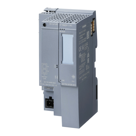
Product overview Properties Order number 6ES7131-6FD01-0BB1 View of the module ① ⑦ Module type and name Function class ② ⑧ LED for diagnostics Color coding module type ③ ⑨ 2D matrix code Function and firmware version ④ ⑩ Wiring diagram Color code for selecting the color identification labels ⑤... - Page 13 ● Color identification labels ● Reference identification label ● Shield connector See also You can find additional information on the accessories in the ET 200SP Distributed I/O System (http://support.automation.siemens.com/WW/view/en/58649293) system manual. Digital input module DI 4x120..230VAC ST (6ES7131-6FD01-0BB1) Manual, 09/2017, A5E32043398-AC...
-
Page 14: Wiring
This section includes the block diagram of the DI 4x120..230VAC ST module with the terminal assignments for a 2-wire, 3-wire and 4-wire connection. Information about wiring of the BaseUnit is available in the system manual ET 200SP distributed I/O system (http://support.automation.siemens.com/WW/view/en/58649293). - Page 15 Wiring 3.1 Wiring and block diagram Connection: 2-wire and 3-wire connection The following figure shows the block diagram and an example of the terminal assignment of the digital input module DI 4x120..230VAC ST on the BaseUnit BU type B1 without AUX terminals (2-wire and 3-wire connection).
- Page 16 Wiring 3.1 Wiring and block diagram Connection: 4-wire connection: The following figure shows the block diagram and an example of the terminal assignment of the digital input DI 4x120..230VAC ST on the BaseUnit BU type B1 with AUX terminals (4-wire connection). ①...
-
Page 17: Parameters/Address Space
The following configurations are possible: ● Central operation with an ET 200SP CPU ● Distributed operation on PROFINET IO in an ET 200SP system ● Distributed operation with PROFIBUS DP in an ET 200SP system When performing the configuration in the user program, use the "WRREC" instruction to transfer the parameters to the module using data records (refer to the section Parameter assignment and structure of parameter data record (Page 26)). -
Page 18: Address Space
Parameters/address space 4.3 Address space Address space The module can be configured differently in STEP 7; see following table. Depending on the configuration, additional/different addresses are assigned in the process image of the inputs. Configuration options of DI 4x120..230VAC ST You can configure the module with STEP 7 (TIA Portal) or with a GSD file. -
Page 19: Interrupts/Diagnostics Alarms
Interrupts/diagnostics alarms Status and fault displays LED displays The figure below shows the LED displays (status and fault displays) of the DI 4x120..230VAC ST. ① DIAG (green/red) ② Channel status (green) ③ PWR (green) Figure 5-1 LED display Digital input module DI 4x120..230VAC ST (6ES7131-6FD01-0BB1) Manual, 09/2017, A5E32043398-AC... - Page 20 The tables below explain the meaning of the Status and fault displays. LED DIAG Table 5- 1 LED DIAG fault display LED DIAG Meaning Backplane bus supply of the ET 200SP not OK Off Module parameters not assigned Flashing Module parameters assigned Module diagnostics is available...
-
Page 21: Diagnostics Alarms
Interrupts/diagnostics alarms 5.2 Diagnostics alarms Diagnostics alarms Diagnostics alarms A diagnostic alarm is generated and the DIAG-LED flashes on the module for each diagnostics event. You can read out the diagnostic alarm, for example, in the diagnostics buffer of the CPU. You can analyze the error code with the user program. Table 5- 4 Diagnostic alarm, meaning and corrective measures Diagnostics alarm... -
Page 22: Technical Specifications
Technical specifications Technical specifications DI 4×120..230VAC ST technical specifications Article number 6ES7131-6FD01-0BB1 General information Product type designation DI 4x120 … 230 V AC ST Firmware version V0.0 FW update possible • usable BaseUnits BU type B1 Color code for module-specific color identifica- CC41 tion plate Product function... - Page 23 Technical specifications 6.1 Technical specifications Article number 6ES7131-6FD01-0BB1 Encoder supply Number of outputs Short-circuit protection No; when using BU type B1, a fuse with 10 A tripping current must be provided Output current 10 A up to 60 °C, max. •...
- Page 24 Technical specifications 6.1 Technical specifications Article number 6ES7131-6FD01-0BB1 Cable length 1 000 m shielded, max. • 600 m unshielded, max. • Encoder Connectable encoders 2-wire sensor • Isochronous mode Isochronous operation (application synchro- nized up to terminal) Interrupts/diagnostics/status information Alarms Diagnostic alarm •...
- Page 25 6.1 Technical specifications Article number 6ES7131-6FD01-0BB1 Dimensions Width 20 mm Height 73 mm Depth 58 mm Weights Weight, approx. 36 g Dimensional drawing See the manual ET 200SP BaseUnits (http://support.automation.siemens.com/WW/view/en/59753521) Digital input module DI 4x120..230VAC ST (6ES7131-6FD01-0BB1) Manual, 09/2017, A5E32043398-AC...
-
Page 26: Parameter Data Record
Parameter data record Parameter assignment and structure of parameter data record The data record of the module has an identical structure, regardless of whether you configure the module with PROFIBUS DP or PROFINET IO. With data record 128, you can reconfigure the module in your user program regardless of your programming. - Page 27 Parameter data record A.1 Parameter assignment and structure of parameter data record Structure of data record 128 Figure A-1 Structure of data record 128 Header information The figure below shows the structure of the header information. Figure A-2 Header information Digital input module DI 4x120..230VAC ST (6ES7131-6FD01-0BB1) Manual, 09/2017, A5E32043398-AC...
- Page 28 Parameter data record A.1 Parameter assignment and structure of parameter data record Parameters The figure below shows the structure of the parameters for channels 0 to 3. You enable a parameter by setting the corresponding bit to "1". Figure A-3 Structure byte x to x+1 for the channels 0 to 3 Error transferring the data record The module always checks all the values of the transferred data record.