Table of Contents
Advertisement
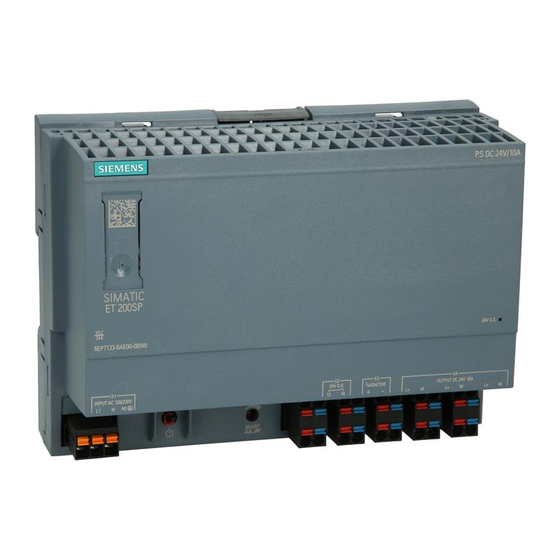
SIMATIC system power supply
SIMATIC ET200SP PS
Manual
SIMATIC ET200SP PS
6EP7133-6AB00-0BN0 24 V/5 A
SIMATIC ET200SP PS
6EP7133-6AE00-0BN0 24 V/10 A
03.2018
A5E43207434
___________________
Overview
___________________
Safety instructions
___________________
Description, device design,
dimension drawing
___________________
Mounting/removal
___________________
Mounting position, mounting
clearances
___________________
Installation
___________________
Technical data
___________________
Safety, approvals, EMC
___________________
Environmental conditions
___________________
Applications
___________________
Environment
___________________
Service & Support
1
2
3
4
5
6
7
8
9
10
11
Advertisement
Table of Contents

Related Manuals for Siemens SIMATIC ET200SP PS 6EP7133-6AB00-0BN0 24 V/5 A


Summary of Contents for Siemens SIMATIC ET200SP PS 6EP7133-6AB00-0BN0 24 V/5 A
- Page 1 ___________________ Overview ___________________ Safety instructions ___________________ Description, device design, SIMATIC system power supply dimension drawing ___________________ Mounting/removal SIMATIC ET200SP PS ___________________ Mounting position, mounting clearances ___________________ Installation Manual ___________________ Technical data ___________________ Safety, approvals, EMC ___________________ Environmental conditions ___________________ Applications ___________________ Environment ___________________...
- Page 2 Note the following: WARNING Siemens products may only be used for the applications described in the catalog and in the relevant technical documentation. If products and components from other manufacturers are used, these must be recommended or approved by Siemens. Proper transport, storage, installation, assembly, commissioning, operation and maintenance are required to ensure that the products operate safely and without any problems.
-
Page 3: Overview
Overview The 1-phase ET200SP PS from the SIMATIC ET200SP product line is a powerful regulated system power supply for automated systems and machines. In addition to a high efficiency, these power supply units have an outstanding overload behavior. The key benefits of the product include: ●... - Page 4 Overview Ordering data The following device options are available: Regulated power supply unit ET200SP PS Type Order number 1-phase 120/230 V AC input, 6EP7133-6AB00-0BN0 24 V/5 A DC output 1-phase 120/230 V AC input, 6EP7133-6AE00-0BN0 24 V/10 A DC output Validity This manual provides information on the following products: ●...
-
Page 5: Table Of Contents
Table of contents Overview..............................3 Safety instructions ........................... 7 General safety instructions ....................... 7 Safety instructions for hazardous zones ................... 7 Description, device design, dimension drawing..................9 Device description ........................9 Connections and terminal designation..................10 Potentiometer .......................... 11 Status displays and signaling ....................12 Block diagram ......................... - Page 6 Table of contents Safety, approvals, EMC ........................35 Safety ............................. 35 Test voltage ..........................36 Approvals ..........................37 EMC ............................37 Environmental conditions ........................39 Applications ............................41 Parallel connection to increase the power rating ..............41 Series connection for increased voltage ................43 Overload protection in the 24 V output circuit ................
-
Page 7: Safety Instructions
Safety instructions General safety instructions WARNING Correct handling of the devices When operating electrical devices, it is inevitable that certain components will carry dangerous voltages. Therefore, failure to handle the units properly can result in death or serious physical injury as well as extensive property damage. - Page 8 Safety instructions 1.2 Safety instructions for hazardous zones SIMATIC ET200SP PS Manual, 03.2018, A5E43207434...
-
Page 9: Description, Device Design, Dimension Drawing
Description, device design, dimension drawing Device description The SIMATIC ET200SP PS is a primary-clocked power supply for connection to a 1-phase AC line supply. An electronically regulated DC voltage that can be set via a potentiometer is available at the output of the device. The output of the device is isolated, no-load proof and short-circuit proof. -
Page 10: Connections And Terminal Designation
Description, device design, dimension drawing 2.2 Connections and terminal designation Connections and terminal designation ① The line input terminals can be used to establish the connection to supply voltage. ② The output terminals are used to connect to the loads to be supplied (see also Section Installation (Page 23)). -
Page 11: Potentiometer
Description, device design, dimension drawing 2.3 Potentiometer Potentiometer ⑤ The potentiometer on the front of the device is used to set the output voltage. The output voltage is set to the rated value at the factory and can be set within certain limits; for example, to compensate voltage drops across long supply lines to the connected load. -
Page 12: Status Displays And Signaling
Description, device design, dimension drawing 2.4 Status displays and signaling Status displays and signaling 6EP7133-6AB00-0BN0 (24 /5 A) 6EP7133-6AE00-0BN0 (24 V/10 A) Status display LED green for 24 V O.K. Signaling contact (13,14) Contact rating (isolated): 30 V AC/0.5 A, 60 V DC/0.3 A, 30 V DC/1 A) for 24 V O.K. Current monitoring terminals Voltage proportional to the output current: ~ 1 V ≙... - Page 13 Description, device design, dimension drawing 2.4 Status displays and signaling Signaling 6EP7133-6AB00-0BN0 (24 /5 A) 6EP7133-6AE00-0BN0 (24 V/10 A) ⑦ Normal operation, output voltage > 20 V ±0.5 V lights up green ④ Signaling contact contact 13-14 closed ⑦ Overload operation or power supply voltage missing ④...
-
Page 14: Block Diagram
Description, device design, dimension drawing 2.5 Block diagram Block diagram Figure 2-5 Block diagram SIMATIC ET200SP PS Manual, 03.2018, A5E43207434... -
Page 15: Dimensions And Weight
Description, device design, dimension drawing 2.6 Dimensions and weight Dimensions and weight Figure 2-6 Dimensions and weight 6EP7133-6AB00-BN0 (24 V/5 A) 6EP7133-6AE00-0BN0 (24 V/10 A) Dimensions (W × H × D) in mm 160 × 117 × 66.5 160 × 117 × 66.5 Weight Approx. - Page 16 Description, device design, dimension drawing 2.6 Dimensions and weight SIMATIC ET200SP PS Manual, 03.2018, A5E43207434...
-
Page 17: Mounting/Removal
Mounting/removal WARNING Installing the device in a housing or a control cabinet SIMATIC ET200SP PS power supplies are built-in devices. They must be installed in a housing or control cabinet where only qualified personnel have access. The device can be mounted in a control cabinet on standard mounting rails (see Chapter Mechanical system (Page 34)) Mounting To mount the device, position it with the mounting rail guide at the upper edge of the... - Page 18 Mounting/removal WARNING Use in hazardous zones If the device is to be used in a hazardous zone (Ex II 3G Ex nA nC IIC T4 Gc) it must be installed in a distributor box with degree of protection IP54 or higher. SIMATIC ET200SP PS Manual, 03.2018, A5E43207434...
-
Page 19: Mounting Position, Mounting Clearances
Mounting position, mounting clearances Standard mounting position The device is mounted on standard mounting rails according to EN 60715 35×7,5/15. The device must be mounted vertically in such a way that the terminals are at the bottom. A clearance of at least 50 mm should be maintained above and below the device (maximum depth of the cable duct, 50 mm). -
Page 20: Other Mounting Positions
Mounting position, mounting clearances 4.2 Other mounting positions Other mounting positions For mounting positions that deviate from the standard mounting position, derating factors (reduction of the output power or the permissible ambient temperature) must be observed in accordance with the following diagrams. Note In the case of mounting positions that deviate from the standard mounting position, reduced mechanical resistance of the devices against vibration and shock must be expected. -
Page 21: 6Ep7133-6Ae00-0Bn0
Mounting position, mounting clearances 4.2 Other mounting positions 4.2.2 6EP7133-6AE00-0BN0 Figure 4-4 Mounting position (2) Note Other mounting positions are not permissible! SIMATIC ET200SP PS Manual, 03.2018, A5E43207434... - Page 22 Mounting position, mounting clearances 4.2 Other mounting positions SIMATIC ET200SP PS Manual, 03.2018, A5E43207434...
-
Page 23: Installation
Installation WARNING Hazard due to electric shock Before installation or maintenance work can begin, the system's main switch must be switched off and measures taken to prevent it being switched on again. If this instruction is not observed, touching live parts can result in death or serious injury. Line-side connection SIMATIC ET200SP PS power supplies are designed for connection to a 1-phase AC line supply (TN or TT system according to IEC 60364-1) with a rated voltage of 120/230 V AC,... - Page 24 Installation 5.1 Line-side connection Protection SIMATIC ET200SP PS Recommended line-side protection 6EP7133-6AB00-0BN0 Miniature circuit breaker (IEC 898) characteristic B, 6 A and C, 3 A 6EP7133-6AE00-0BN0 Miniature circuit breaker (IEC 898) characteristic B, 10 A and C, 6 A The protective conductor of the line supply must be connected at the PE terminal. NOTICE Country-specific regulations must be observed when installing.
-
Page 25: Output-Side Connection
Installation 5.2 Output-side connection Output-side connection SIMATIC ET200SP PS power supplies provide an isolated (= non-grounded) SELV output voltage (Safety Extra Low Voltage). The output of the power supply is no-load, overload, and short-circuit proof. If an overload occurs, the electronic current limitation limits the output current to a maximum value (refer to chapter Technical data (Page 27)). - Page 26 Installation 5.2 Output-side connection SIMATIC ET200SP PS Manual, 03.2018, A5E43207434...
-
Page 27: Technical Data
Technical data Note Technical data apply for a rated input voltage, rated load and 25 °C ambient temperature if nothing else is specified. Input 6EP7133-6AB00-0BN0 (24 V/5 A) 6EP7133-6AE00-0BN0 (24 V/10 A) Input 1-phase, AC 1-phase, AC Rated voltage U 120 - 230 V 120 - 230 V in rated... - Page 28 Technical data 6.1 Input Figure 6-1 Power-failure buffering SIMATIC ET200SP PS Manual, 03.2018, A5E43207434...
-
Page 29: Output
Technical data 6.2 Output Output 6EP7133-6AB00-0BN0 (24 V/5 A) 6EP7133-6AE00-0BN0 (24 V/10 A) Output Regulated, isolated DC voltage Regulated, isolated DC voltage Rated voltage U 24 V 24 V out rated Total tolerance, static ± Static line regulation, approx. ± 0.1 % 0.5 % Static load regulation, approx. - Page 30 Technical data 6.2 Output 6EP7133-6AB00-0BN0 (24 V/5 A) 6EP7133-6AE00-0BN0 (24 V/10 A) Duration of the overload capability 100 ms 100 ms for an overcurrent condition caused by a short circuit in operation. once-only once-only Remark • Can be connected in parallel to increase the power rating Number of devices that can be connected in parallel to increase...
- Page 31 Technical data 6.2 Output Figure 6-4 Output characteristic 6EP7133-6AE00-0BN0 The device supplies a constant output voltage until the current limit is reached. In the event of an overload, the output current and the output voltage are reduced. SIMATIC ET200SP PS Manual, 03.2018, A5E43207434...
-
Page 32: Efficiency
Technical data 6.3 Efficiency Efficiency 6EP7133-6AB00-0BN0 (24 V/5 A) 6EP7133-6AE00-0BN0 (24 V/10 A) Efficiency at U 87 %/88 % 89.5 %/90 % out rated out rated 120 V/230 V AC approx. Power loss at U 17 W/15 W 27 W/26 W out rated out rated 120 V/230 V AC approx. -
Page 33: Closed-Loop Control
Technical data 6.4 Closed-loop control Closed-loop control 6EP7133-6AB00-0BN0 (24 V/5 A) 6EP7133-6AE00-0BN0 (24 V/10 A) Dyn. line regulation 0.3 % 0.3 % ±15 %), max. in rated Dyn. load regulation : 10/90/10 %), U ± max. Dyn. load regulation : 10/90/10 %), U ±... -
Page 34: Mechanical System
Mounting Can be snapped onto standard TH35 15/7,5 mounting rails (EN 60715) Dimension drawing See chapter Dimensions and weight (Page 15) CAD data that can be downloaded from the Internet: 6EP7133-6AB00-0BN0 (http://www.automation.siemens.com/bilddb/index.aspx?objKey=G_KT01_XX_01416) 6EP7133-6AE00-0BN0 (http://www.automation.siemens.com/bilddb/index.aspx?objKey=G_KT01_XX_01419) SIMATIC ET200SP PS Manual, 03.2018, A5E43207434... -
Page 35: Safety, Approvals, Emc
Safety, approvals, EMC Safety 6EP7133-6AB00-0BN0 (24 V/5 A) 6EP7133-6AE00-0BN0 (24 V/10 A) Primary/secondary galvanic isolation Galvanic isolation SELV output voltage U acc. to EN 60950-1 Transformer according to EN 61558-2-16 Protection class Class I Degree of protection (EN 60529) IP20 Leakage current, typ. -
Page 36: Test Voltage
Safety, approvals, EMC 7.2 Test voltage Test voltage Figure 7-1 Test voltage diagram Only the manufacturer can perform the type test and production test; users can also perform the field test. Preconditions for performing the field test: Tests (A) & (B) ●... -
Page 37: Approvals
Safety, approvals, EMC 7.3 Approvals Approvals 6EP7133-6AB00-0BN0 (24 V/5 A) 6EP7133-6AE00-0BN0 (24 V/10 A) CE marking yes, (2014/35/EU, 2014/30/EU and 2011/65/EU) CSA approval yes, CSA C22.2 No. 60950-1, being prepared UL/cUL approval cULus-listed (UL 508, CSA 22.2 No. 107.1), File E197259 Explosion protection UL/cUL: ANSI/ISA-12.12.01-2015 Class I, Div. - Page 38 Safety, approvals, EMC 7.4 EMC SIMATIC ET200SP PS Manual, 03.2018, A5E43207434...
-
Page 39: Environmental Conditions
Environmental conditions 6EP7133-6AB00-0BN0 (24 V/5 A) 6EP7133-6AE00-0BN0 (24 V/10 A) Ambient temperature -30 … 70 °C for natural convection (self convection) Derating at ≤ 60 °C: Remark • 85 V AC and 170 V AC: 90 % P out rated ≥... - Page 40 Environmental conditions SIMATIC ET200SP PS Manual, 03.2018, A5E43207434...
-
Page 41: Applications
Applications Parallel connection to increase the power rating To increase the power rating, power supplies of the same type can be directly connected in parallel. The following must be observed: ● The cables connected to each power supply at terminals "+" and "-" must have identical lengths and the same cable cross-sections (or the same impedance) up to a common external connection point (terminal strip) if possible. - Page 42 Applications 9.1 Parallel connection to increase the power rating NOTICE Protective circuit for the parallel connection of more than two power supplies When connecting more than two power supplies in parallel, additional measures must be taken to prevent high reverse currents in the event of a secondary device fault. For this purpose, a suitable protective circuit (e.g.
-
Page 43: Series Connection For Increased Voltage
Note For additional details, see Catalog KT 10.1 Chapter 15 Technical information and configuring (see (http://w3app.siemens.com/mcms/infocenter/content/en/Pages/order_form.aspx?nodeKey=k ey_518431&infotype=catalogs)). WARNING SELV is not guaranteed in the case of a fault When connecting two power supplies in series, the continuous, permissible SELV voltage of a maximum of 60 VDC according to EN 60950-1 cannot be guaranteed in the case of a fault. -
Page 44: Overload Protection In The 24 V Output Circuit
SIMATIC S7-1200/1500/300/400, for STEP 7 Classic and TIA Portal at no charge. You can find additional information at: Manual SITOP selectivity modules (https://support.industry.siemens.com/cs/ww/en/view/108989004) Figure 9-3 Electronic protection of 24 V loads using the SITOP PSE200U selectivity module SIMATIC ET200SP PS... -
Page 45: Protection Against Short-Time Voltage Dips
Applications 9.4 Protection against short-time voltage dips Protection against short-time voltage dips For a drop in the line-side supply voltage, the 24 V power supply still maintains the output voltage for a short time in the millisecond range (see Chapter Technical data (Page 27)). For line supplies that manifest frequent brief voltage dips, in order to increase the power supply reliability, it may make sense to increase the line buffering time in the device using an additional SITOP PSE201U buffer module. -
Page 46: Protecting Against Longer Power Failures
PC. You can find additional information at: Manual, DC UPS with capacitors (https://support.industry.siemens.com/cs/ww/en/ps/18042/man) Using DC UPS SITOP UPS1600 and SITOP UPS1100 battery modules, buffer times in the range of hours can be implemented. Intelligent battery management using Energy Storage Link automatically detects the UPS1100 energy storage device, and ensures optimum temperature-controlled charging and continuous monitoring. - Page 47 – make it easy to integrate operating and diagnostics information into STEP 7 user programs. Preconfigured UPS faceplates for WinCC visualization can be downloaded at no charge. You can find additional information at: DC UPS SITOP UPS1600/UPS1100 Manual (https://support.industry.siemens.com/cs/ww/en/view/84977415) SIMATIC ET200SP PS Manual, 03.2018, A5E43207434...
- Page 48 Applications 9.5 Protecting against longer power failures SIMATIC ET200SP PS Manual, 03.2018, A5E43207434...
-
Page 49: Environment
Environment The devices are in conformance with RoHS. As a rule, only non-silicon precipitating materials are used. Disposal guidelines Packaging and packaging aids can and should always be recycled. The product itself may not be disposed of as domestic refuse. SIMATIC ET200SP PS Manual, 03.2018, A5E43207434... - Page 50 Environment SIMATIC ET200SP PS Manual, 03.2018, A5E43207434...
-
Page 51: Service & Support
Technical support for all IA/DT products can be accessed through the following communication channels: ● Telephone: + 49 (0) 911 895 7222 ● Internet: Web form for support request (http://www.siemens.de/automation/support-request) Technical documentation on the Internet Operating instructions and manuals for SITOP are available in the Internet: Operating instructions/manuals (http://www.siemens.com/sitop/manuals) - Page 52 Service & Support Contact persons If you have any questions regarding the use of our products, then contact the Siemens contact person in your regional Siemens sales office. You can find these addresses as follows: ● On the Internet (http://www.automation.siemens.com/partner) ●...