Siemens SIMATIC ET 200SP Manual
Technology module tm count 1x24v
Hide thumbs
Also See for SIMATIC ET 200SP:
- System manual (320 pages) ,
- Manual (270 pages) ,
- Operating instructions manual (166 pages)
Table of Contents
Advertisement
Quick Links
F/deTechnology Module TM Count 1x24V
(6ES7138‑6AA00‑0BA0)
SIMATIC
ET 200SP
Technology Module
TM Count 1x24V
(6ES7138‑6AA00‑0BA0)
Manual
10/2013
A5E33002339-AA
___________________
Preface
___________________
Documentation guide
___________________
Product overview
___________________
Wiring
___________________
Configuring/address space
___________________
Interrupts/diagnostic
messages
___________________
Technical specifications
___________________
Parameter data records
1
2
3
4
5
6
A
Advertisement
Table of Contents

Related Manuals for Siemens SIMATIC ET 200SP


Summary of Contents for Siemens SIMATIC ET 200SP
- Page 1 ___________________ F/deTechnology Module TM Count 1x24V Preface (6ES7138‑6AA00‑0BA0) ___________________ Documentation guide ___________________ Product overview SIMATIC ___________________ Wiring ET 200SP ___________________ Technology Module Configuring/address space TM Count 1x24V ___________________ Interrupts/diagnostic (6ES7138‑6AA00‑0BA0) messages Manual ___________________ Technical specifications ___________________ Parameter data records 10/2013 A5E33002339-AA...
- Page 2 Note the following: WARNING Siemens products may only be used for the applications described in the catalog and in the relevant technical documentation. If products and components from other manufacturers are used, these must be recommended or approved by Siemens. Proper transport, storage, installation, assembly, commissioning, operation and maintenance are required to ensure that the products operate safely and without any problems.
-
Page 3: Preface
Security information Siemens provides automation and drive products with industrial security functions that support the secure operation of plants or machines. They are an important component in a holistic industrial security concept. With this in mind, our products undergo continuous development. - Page 4 Siemens accepts no liability for the use of the open source software over and above the intended program sequence, or for any faults caused by modifications to the software.
-
Page 5: Table Of Contents
Table of contents Preface ............................3 Documentation guide ........................7 Product overview ........................... 9 Properties ..........................9 Functions ..........................12 2.2.1 Detection of counting signals ....................12 2.2.2 Measured value determination ....................14 2.2.3 Switching the outputs at comparison values................15 2.2.4 Position input for Motion Control ..................... - Page 6 Table of contents Technology Module TM Count 1x24V (6ES7138‑6AA00‑0BA0) Manual, 10/2013, A5E33002339-AA...
-
Page 7: Documentation Guide
Documentation for technology module TM Count 1x24V Topic Documentation Most important contents System System manual Application planning • description ET 200SP distributed I/O system Installing • (http://support.automation.siemens.com/WW/vi Connecting • ew/en/58649293) Commissioning System manual • S7-1500 Automation System (http://support.automation.siemens.com/WW/vi ew/en/59191792) Device manual Connecting •... - Page 8 S7-1500 Motion Control Programming • (http://support.automation.siemens.com/WW/vi Commissioning ew/en/59381279) • Diagnostics • SIMATIC manuals All current manuals for the SIMATIC products are available for download free of charge from the Internet (http://www.siemens.com/automation/service&support). Technology Module TM Count 1x24V (6ES7138‑6AA00‑0BA0) Manual, 10/2013, A5E33002339-AA...
-
Page 9: Product Overview
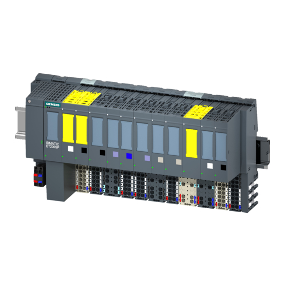
Product overview Properties Order number 6ES7138-6AA00-0BA0 View of the module Figure 2-1 View of the TM Count 1x24V module Technology Module TM Count 1x24V (6ES7138‑6AA00‑0BA0) Manual, 10/2013, A5E33002339-AA... - Page 10 Product overview 2.1 Properties Properties The TM Count 1x24V technology module has the following properties: ● Technical properties – One channel – Interfaces: 24 V encoder signals A, B and N from sourcing, sinking or push pull encoders and sensors 24 V encoder supply output, short-circuit proof DI0, DI1 and DI2 digital input signals DQ0 and DQ1 digital output signals...
- Page 11 BaseUnits that you can use with the technology module, please refer to the product information on the documentation for the ET 200SP Distributed I/O System (http://support.automation.siemens.com/WW/view/en/73021864). For detailed information on the installation procedure, refer to the ET 200SP Distributed I/O System (http://support.automation.siemens.com/WW/view/en/58649293) system manual. Technology Module TM Count 1x24V (6ES7138‑6AA00‑0BA0) Manual, 10/2013, A5E33002339-AA...
-
Page 12: Functions
Product overview 2.2 Functions Functions 2.2.1 Detection of counting signals Counting refers to the detection and summation of events. The counters of the technology module detect encoder signals and pulses and evaluate them accordingly. The count direction can be specified using encoder or pulse signals or through the user program. You can control the counting processes with the digital inputs. - Page 13 Product overview 2.2 Functions Capture You can configure an external reference signal edge that triggers the saving of the current counter value as Capture value. The following external signals can trigger the Capture function: ● Rising or falling edge of a digital input ●...
-
Page 14: Measured Value Determination
Product overview 2.2 Functions 2.2.2 Measured value determination The following measuring functions are available: Measurement type Description Frequency measurement The mean frequency is calculated at set measuring intervals on the basis of the time profile of the count pulses and returned in hertz as the floating point number. -
Page 15: Switching The Outputs At Comparison Values
Motion Control". Additional information A detailed description of the use of Motion Control and its configuration is available in the function manual S7-1500 Motion Control as a download from the Internet (http://support.automation.siemens.com/WW/view/en/59381279). Technology Module TM Count 1x24V (6ES7138‑6AA00‑0BA0) Manual, 10/2013, A5E33002339-AA... -
Page 16: Additional Functions
Product overview 2.2 Functions 2.2.5 Additional functions Hardware interrupts The technology module can trigger a hardware interrupt in the CPU, for example, if a compare event occurs, in the event of overflow or underflow, in the event of a zero crossing of the counter and/or of a change of count direction (direction reversal). -
Page 17: Wiring
ET 200SP Distributed I/O System (http://support.automation.siemens.com/WW/view/en/73021864). You can find information about selecting a suitable BaseUnit in the ET 200SP Distributed I/O System (http://support.automation.siemens.com/WW/view/en/58649293) system manual and ET 200SP BaseUnits (http://support.automation.siemens.com/WW/view/en/58532597/133300) device manual. You can find information on wiring the BaseUnit, connecting cable shields, etc. in the Connecting section of the ET 200SP Distributed I/O System (http://support.automation.siemens.com/WW/view/en/58649293) system manual. - Page 18 Wiring 3.1 Pin assignment Terminal assignment of the BaseUnit The table below shows the pin assignment, using the BaseUnit BU15-P16+A0+2B as an example. Table 3- 1 Pin assignment of the BaseUnit BU15-P16+A0+2B View Signal name Designation 24 V incremental encoder 24 V pulse encoder With Without...
- Page 19 Wiring 3.1 Pin assignment Block diagram The figure below shows the block diagram of the technology module with a connected incremental encoder. You must ground the shields of the cables between encoder and technology module both through the shield terminal on the BaseUnit (shield bracket and terminal) and also on the encoder.
- Page 20 Wiring 3.1 Pin assignment L+/M supply voltage Connect the supply voltage (DC 24V) to the L+ and M connections. An internal protective circuit protects the technology module from polarity reversal of the supply voltage. The technology module monitors the connection of the supply voltage. 24VDC encoder supply To supply the encoder and sensors at the digital inputs, the technology module supplies the DC 24V supply voltage at the 24VDC output with reference to M.
- Page 21 Wiring 3.1 Pin assignment You can connect the following encoders or sensors at inputs A, B and N: ● Sourcing output: The inputs A, B and N are switched by the encoder or sensor after 24VDC . ● Sinking output: The inputs A, B and N are switched by the encoder or sensor after ground M .
- Page 22 Wiring 3.1 Pin assignment Input filters for digital inputs To suppress interferences, you can configure an input filter for the digital inputs. You can specify the following values for the filter time: ● None ● 0.05 ms ● 0.1 ms (default) ●...
-
Page 23: Configuring/Address Space
Configuring/address space Configuring Introduction The technology module is configured and assigned parameters with the configuration software. The technology module functions are controlled and monitored by the user program. System environment The technology module can be used in the following system environments: Applications Components required Configuration software... - Page 24 ● In the Counting, Measurement and Position Input Function Manual available as download on the Internet (http://support.automation.siemens.com/WW/view/en/59709820) ● In the STEP 7 (TIA Portal) information system under "Using technology functions > Counting, measurement and position detection" > Counting, measurement and position detection (S7-1500)"...
-
Page 25: Reaction To Cpu Stop
Configuring/address space 4.2 Reaction to CPU STOP Reaction to CPU STOP Reaction to CPU STOP You set the response of the technology module to CPU STOP for each channel in the basic parameters of the device configuration. Table 4- 1 Response of the technology module to CPU STOP depending on parameter assignment Basic parameters Reaction to CPU STOP... -
Page 26: Address Space
Configuring/address space 4.3 Address space Address space Address space of the technology module Table 4- 2 Range of the input addresses and output addresses of the TM Count 1x24V Inputs Outputs Range 16 bytes 12 bytes Table 4- 3 Range of the input and output addresses of the TM Count 1x24V in the "Position detection for Motion Control"... -
Page 27: Control And Feedback Interface
A detailed description of the TM Count 1x24V control and feedback bits is available in the Counting, Measurement and Position Detection function manual which can be downloaded from the Internet (http://support.automation.siemens.com/WW/view/en/59709820). Note The control and feedback interface is compatible with the control and feedback interface of the TM Count 2x24V technology module of the S7-1500 automation system. - Page 28 Configuring/address space 4.4 Control and feedback interface Offset to the start Parameter Meaning address Byte 8 LD_SLOT_1* Specifies the significance of the value in Slot 1 Bit 7 Bit 6 Bit 5 Bit 4 No action, idle Load counter value Reserve Load start value Load comparison value 0...
-
Page 29: Assignment Of The Feedback Interface
Configuring/address space 4.4 Control and feedback interface 4.4.2 Assignment of the feedback interface The user program receives current values and status information from the technology module by means of the feedback interface. Feedback interface The following table shows the assignment of the feedback interface: Offset to the start Parameter Meaning... - Page 30 Configuring/address space 4.4 Control and feedback interface Technology Module TM Count 1x24V (6ES7138‑6AA00‑0BA0) Manual, 10/2013, A5E33002339-AA...
-
Page 31: Interrupts/Diagnostic Messages
Interrupts/diagnostic messages Status and error displays LEDs The figure below shows you the LED displays (status and error displays) of TM Count 1x24V. Figure 5-1 LEDs of the TM Count 1x24V Technology Module TM Count 1x24V (6ES7138‑6AA00‑0BA0) Manual, 10/2013, A5E33002339-AA... - Page 32 Interrupts/diagnostic messages 5.1 Status and error displays Meaning of the LED displays The following tables explain the meaning of the status and error displays. Remedial measures for diagnostic messages can be found in the section Diagnostic messages (Page 34). Table 5- 1 Status and error displays DIAG LED DIAG Meaning...
- Page 33 Interrupts/diagnostic messages 5.1 Status and error displays ChannelLEDs The LEDs A, B, N and DIm indicate the current level of the associated signals. The LEDs of the digital outputs DQm indicate the desired state. The LEDs UP and DN indicate the logical counting direction. The flashing frequency of the channel LEDs is limited to ca.
-
Page 34: Diagnostic Messages
Interrupts/diagnostic messages 5.2 Diagnostic messages Diagnostic messages Diagnostic alarms If a diagnostic alarm is pending, the DIAG LED flashes red. The diagnostic alarms are displayed as clear text in STEP 7 (TIA Portal) in the online and diagnostics view. You can evaluate the error codes with the user program. The following diagnostics can be signaled: Table 5- 5 Diagnostic alarms, their meaning and remedies... - Page 35 Interrupts/diagnostic messages 5.2 Diagnostic messages Diagnostic alarm Error Meaning To correct or avoid errors code Faulty external Error at supply voltage L+ Check the L+ supply voltage • • auxiliary voltage Possible causes: Check the wiring of the supply voltage •...
-
Page 36: Interrupts
Interrupts/diagnostic messages 5.3 Interrupts Interrupts 5.3.1 Trigger a diagnostic interrupt Enabling the diagnostic interrupts You enable the diagnostic interrupt for wire break and the diagnostic interrupts for additional errors in the basic parameters during device configuration. A list of all errors that can trigger a diagnostic interrupt is available at Cause of the error triggering a diagnostic interrupt (Page 37). -
Page 37: Cause Of The Error Triggering A Diagnostic Interrupt
Interrupts/diagnostic messages 5.3 Interrupts 5.3.2 Cause of the error triggering a diagnostic interrupt Which errors can trigger a diagnostic interrupt? The technology module can trigger the following diagnostic interrupts: Table 5- 6 Possible diagnostic interrupts Diagnostic interrupt Monitoring Monitoring is always active. A diagnostic interrupt is Internal error •... -
Page 38: Triggering Of A Hardware Interrupt
Interrupts/diagnostic messages 5.3 Interrupts 5.3.3 Triggering of a Hardware Interrupt Introduction For the technology module, you can configure which events are to trigger a hardware interrupt during operation. What is a Hardware Interrupt? The technology module will trigger a hardware interrupt as configured in response to specific events/states. -
Page 39: Events Which Can Trigger A Hardware Interrupt
Interrupts/diagnostic messages 5.3 Interrupts 5.3.4 Events which can trigger a hardware interrupt Which events can trigger a hardware interrupt? A hardware interrupt is triggered if the condition for changing the respective status bit or event bit in the feedback interface is fulfilled. The EventType tag, among others, is entered in the start information of the assigned hardware interrupt OB when a hardware interrupt is triggered. - Page 40 Interrupts/diagnostic messages 5.3 Interrupts Technology Module TM Count 1x24V (6ES7138‑6AA00‑0BA0) Manual, 10/2013, A5E33002339-AA...
-
Page 41: Technical Specifications
Technical specifications 6ES7138-6AA00-0BA0 Product type designation TM Count 1x24V General information BaseUnits that can be used BU type A0 Product function I&M data Yes; I&M0 to I&M3 Engineering with STEP 7 TIA Portal can be configured/integrated as of version V12 SP1 / V13 STEP 7 can be configured/integrated as of version V5.5 SP3 / V5.5 SP4 Supply voltage... - Page 42 Technical specifications 6ES7138-6AA00-0BA0 Digital input functions, configurable Gate start/stop Capture Synchronization Freely assignable digital input Input voltage Rated value, DC 24 V For signal "0" -30 V to +5 V For signal "1" +11 V to +30 V Permitted voltage at input, min. -30 V Permitted voltage at input, max.
- Page 43 Technical specifications 6ES7138-6AA00-0BA0 Output voltage for signal "1", min. 23.2 V; L+ (-0.8 V) Output current for signal "1" rated value 0.5 A; per digital output for signal "1" permissible range, max. 0.6 A; per digital output for signal "1" minimum load current 2 mA for signal "0"...
- Page 44 Technical specifications 6ES7138-6AA00-0BA0 Isochronous mode Isochronous mode (application synchronized until terminal) Bus cycle time (TDP), min. 250 µs Interrupts/diagnostics/status information Activation of substitute values Yes; configurable Interrupts Diagnostic interrupt Hardware interrupt Diagnostic messages Monitoring of supply voltage Wire break Short circuit A/B transition error with incremental encoder Group error LED diagnostics display...
- Page 45 Technical specifications 6ES7138-6AA00-0BA0 Measuring functions Measuring time, configurable Dyn. measuring time adjustment Number of threshold values, configurable Measuring range 0.04 Hz Frequency measurement, min. • 800 kHz Frequency measurement, max. • 1.25 µs Period measurement, min. • 25 s Period measurement, max. •...
- Page 46 Technical specifications Derating information for total current of outputs If the digital outputs of the TM Count 1x24V are operated with resistive or inductive loads, you should derate the total current of the loads at the digital outputs of the technology module.
- Page 47 If the switching frequency is greater than 0.5 Hz or there is greater inductance at the digital outputs, the total current must be reduced further. Dimensional drawing See ET 200SP BaseUnits (http://support.automation.siemens.com/WW/view/en/58532597/133300) manual Technology Module TM Count 1x24V (6ES7138‑6AA00‑0BA0) Manual, 10/2013, A5E33002339-AA...
- Page 48 Technical specifications Technology Module TM Count 1x24V (6ES7138‑6AA00‑0BA0) Manual, 10/2013, A5E33002339-AA...
-
Page 49: Parameter Data Records
Parameter data records You may edit the module parameters in RUN. The WRREC instruction is used to transfer the parameters to the module using data record 128. If errors occur during the transfer of parameters with the WRREC instruction, the module continues operation with the previous parameter assignment. - Page 50 Parameter data records Bit → Bit 7 Bit 6 Bit 5 Bit 4 Bit 3 Bit 2 Bit 1 Bit 0 Byte ↓ 6...7 Counter inputs Sensor type: Signal evaluation: Signal type: : Sourcing output : Single 0000 : Pulse (A) : Sinking output : Double 0001...
- Page 51 Parameter data records Bit → Bit 7 Bit 6 Bit 5 Bit 4 Bit 3 Bit 2 Bit 1 Bit 0 Byte ↓ 10...15 Behavior of DQ0/1 Set output (DQ1): Set output (DQ0): 0000 : Use by user program 0000 : Use by user program 0001 : Between comparison value and high counting...
- Page 52 Parameter data records Bit → Bit 7 Bit 6 Bit 5 Bit 4 Bit 3 Bit 2 Bit 1 Bit 0 Byte ↓ Behavior of DI1: See Byte 16 Behavior of DI2: See Byte 16 Frequency: Reserved Filter time: : Once 0000 : None 0001...
- Page 53 Parameter data records Bit → Bit 7 Bit 6 Bit 5 Bit 4 Bit 3 Bit 2 Bit 1 Bit 0 Byte ↓ Specify measured value Reserved Time base for velocity measurement: Measured variable: : 1 ms : Frequency : 10 ms : Period : 100 ms : Velocity...
- Page 54 Parameter data records Technology Module TM Count 1x24V (6ES7138‑6AA00‑0BA0) Manual, 10/2013, A5E33002339-AA...