Siemens Sitrans FX300 Operating Instructions Manual
Vortex flowmeters
Hide thumbs
Also See for Sitrans FX300:
- Supplementary instructions manual (22 pages) ,
- Quick start manual (16 pages)
Table of Contents
Advertisement
Quick Links
Advertisement
Table of Contents

Related Manuals for Siemens Sitrans FX300


Summary of Contents for Siemens Sitrans FX300
- Page 2 IMPRINT :::::::::::::::::::::::::::::::::: All rights reserved. It is prohibited to reproduce this documentation, or any part thereof, without the prior written authorisation of Siemens. Subject to change without notice. Copyright 2009 by Siemens www.siemens.com/flow 06/2009 - SFIDK.PS.050.F2.02 A5E02100423...
-
Page 3: Table Of Contents
CONTENTS SITRANS FX300 1 Safety instructions 1.1 Intended use ........................6 1.2 Certifications ........................7 1.3 Safety instructions from the manufacturer ..............8 1.3.1 Copyright and data protection ....................8 1.3.2 Disclaimer ..........................8 1.3.3 Product liability and warranty ....................9 1.3.4 Information concerning the documentation................ - Page 4 CONTENTS SITRANS FX300 4 Electrical connections 4.1 Safety instructions......................31 4.2 Connecting the signal converter ..................32 4.3 Electrical connection of current and pulse output ............33 4.3.1 Power supply......................... 34 4.3.2 Totalizer / pulse output......................34 4.4 Grounding connections....................36 4.5 Protection category ......................
- Page 5 CONTENTS SITRANS FX300 8 Technical data 8.1 Functional principle......................66 8.2 Technical data......................... 67 8.3 Dimensions and weights ....................70 8.3.1 Flange versions........................70 8.3.2 Sandwich version ........................73 8.4 Flow tables ........................75 9 Notes 06/2009 - SFIDK.PS.050.F2.02 A5E02100423...
-
Page 6: Safety Instructions
SAFETY INSTRUCTIONS SITRANS FX300 1.1 Intended use The vortex flowmeters are made to measure the flow of gases, steam and liquids. The devices are particularly suitable for the measurement of: • Clean liquids with low viscosity (< 10 cP) • Hydrocarbons with low viscosity (< 10 cP) •... -
Page 7: Certifications
SAFETY INSTRUCTIONS SITRANS FX300 1.2 Certifications CE marking The device fulfils the statutory requirements of the following EC directives: • Pressure Equipment Directive 97/23/EC • Low Voltage Directive 73/23/EEC • EMC Directive 89/336/EC as well as • EN 61010 • EMC specification acc. to EN 61326/A1 •... -
Page 8: Safety Instructions From The Manufacturer
SAFETY INSTRUCTIONS SITRANS FX300 1.3 Safety instructions from the manufacturer 1.3.1 Copyright and data protection The contents of this document have been created with great care. Nevertheless, we provide no guarantee that the contents are correct, complete or up-to-date. The contents and works in this document are subject to German copyright. Contributions from third parties are identified as such. -
Page 9: Product Liability And Warranty
SAFETY INSTRUCTIONS SITRANS FX300 1.3.3 Product liability and warranty The operator shall bear responsibility for the suitability of the device for the specific purpose. The manufacturer accepts no liability for the consequences of misuse by the operator. Improper installation and operation of the devices (systems) will cause the warranty to be void. The respective "Standard Terms and Conditions"... -
Page 10: Warnings And Symbols Used
SAFETY INSTRUCTIONS SITRANS FX300 1.3.5 Warnings and symbols used Safety warnings are indicated by the following symbols. DANGER! This information refers to the immediate danger when working with electricity. DANGER! This warning refers to the immediate danger of burns caused by heat or hot surfaces. -
Page 11: Device Description
DEVICE DESCRIPTION SITRANS FX300 2.1 Scope of delivery INFORMATION! Inspect the cartons carefully for damage or signs of rough handling. Report damage to the carrier and to the local office of the manufacturer. INFORMATION! Check the packing list to check if you received completely all that you ordered. -
Page 12: Devices With Connection Flange
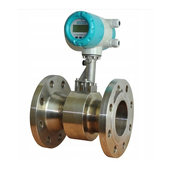
DEVICE DESCRIPTION SITRANS FX300 2.2.1 Devices with connection flange The measuring system consists of a measuring sensor and a signal converter. These elements form a permanent mechanical unit. Figure 2-2: Flanged devices with display 1 Version with temperature sensor 2 Version with temperature sensor and optional pressure sensor 3 Version with temperature sensor, optional pressure sensor and shut-off valve 2.2.2 Sandwich version... -
Page 13: Device Description
DEVICE DESCRIPTION SITRANS FX300 2.2.3 Device description Figure 2-4: Device description 1 Signal converter 2 Cable feedthrough grey, standard version 3 Pressure sensor, optional 4 Shut-off valve, optional 5 Measuring sensor 6 Centering ring 2.2.4 Free air delivery measurement - FAD (optional) A (air) compressor draws air from the ambient atmosphere, compresses it and delivers it at the required pressure. -
Page 14: Gross Heat Meter
DEVICE DESCRIPTION SITRANS FX300 2.2.5 Gross heat meter In almost all applications with saturated steam, the steam is used for heating. It is much more interesting to know how great the heat flow volume is that is available to the process, than to know how great the flow is in kg/h. -
Page 15: Dual Seal
Regular maintenance should be performed by the customer to ensure this Dual Seal notification system is working properly or that there is no leak. If a leakage is noticed: Siemens customer service should be contacted for servicing or replacement of the meter. 06/2009 - SFIDK.PS.050.F2.02 A5E02100423 www.siemens.com/flow... -
Page 16: Nameplate
DEVICE DESCRIPTION SITRANS FX300 2.3 Nameplate INFORMATION! Look at the device nameplate to ensure that the device is delivered according to your order. Check for the correct supply voltage printed on the nameplate. Figure 2-5: Example for nameplate 1 Device type 2 Manufacturer 3 Notified ATEX &... -
Page 17: Installation
INSTALLATION SITRANS FX300 3.1 Notes on installation INFORMATION! Inspect the cartons carefully for damage or signs of rough handling. Report damage to the carrier and to the local office of the manufacturer. INFORMATION! Check the packing list to check if you received completely all that you ordered. -
Page 18: Installation Condtitions
INSTALLATION SITRANS FX300 3.4 Installation condtitions INFORMATION! For accurate volumetric flow measurement the measuring device needs a completely filled pipe and a fully developed flow profile. Please observe the instructions regarding inlet and outlet pipe runs as well as the installation position. -
Page 19: Measurement Of Liquids
INSTALLATION SITRANS FX300 3.4.1 Measurement of liquids Prohibited installation Prohibited installation Prohibited installation Prohibited installation Figure 3-2: Upper pipe bend CAUTION! Prohibited: Installing the device in an upper pipe bend 1, because there is a risk of gas bubbles 2 forming. Gas bubbles can lead to pressure surges and inaccurate measurement. - Page 20 INSTALLATION SITRANS FX300 Recommended installations for measurement of liquids Recommended installations for measurement of liquids Recommended installations for measurement of liquids Recommended installations for measurement of liquids CAUTION! It is absolutely necessary to comply with the required inlet and outlet runs.
-
Page 21: Measurement Of Vapours And Gases
INSTALLATION SITRANS FX300 3.4.2 Measurement of vapours and gases Prohibited installation 1 Lower pipe bends 2 Condensate DANGER! Prohibited: Installing the device in a lower pipe bend 1, because there is a risk of condensate forming 2. Condensate can lead to cavitation and inaccurate measurement. Under certain circumstances the device can be destroyed and the measured product can leak. -
Page 22: Pipelines With Control Valve
INSTALLATION SITRANS FX300 3.4.3 Pipelines with control valve INFORMATION! To ensure smooth and correct measurement, the manufacturer recommends not installing the measuring device downstream from a control valve. This would run the risk of vortex formation, which would distort the measuring result. -
Page 23: Turning The Connection Housing
INSTALLATION SITRANS FX300 3.4.5 Turning the connection housing DANGER! All work on the device electrics may only be carried out by appropriately trained personnel. The regional occupational health and safety directives must always be observed. CAUTION! Do not damage the electrical cable by overtwisting it. -
Page 24: Turning The Display
INSTALLATION SITRANS FX300 3.4.6 Turning the display DANGER! All work on the device electrics may only be carried out by appropriately trained personnel. The regional occupational health and safety directives must always be observed. INFORMATION! If the measuring device is installed in a vertical pipe, you will have to turn the display by 90 ;... -
Page 25: Heat Insulation
INSTALLATION SITRANS FX300 3.4.7 Heat insulation CAUTION! The area above the converter support must not be heat-insulated. The heat insulation 3 may only extend to the maximum height 1 shown below up to the connecting screws of the measuring sensor. -
Page 26: Inlet And Outlet Runs
INSTALLATION SITRANS FX300 3.5 Inlet and outlet runs 3.5.1 Minimum inlet runs 1 General inlet run without disturbing flow ≥ 20 DN 2 Behind a control valve ≥ 50 DN 3 After a pipe diameter reduction ≥ 20 DN 1 After a single bend 90° ≥ 20 DN 2 After a double bend 2x90°... -
Page 27: Minimum Outlet Runs
INSTALLATION SITRANS FX300 3.5.2 Minimum outlet runs Figure 3-8: Minimum outlet runs 1 Upstream of pipe expanders, pipe bends, control valves, etc. ≥ 5 DN 2 Upstream of metering points ≥ 5…6 DN INFORMATION! The interior of the pipe at the metering points must be free of burrs and other flow impediments. -
Page 28: Installation
INSTALLATION SITRANS FX300 3.6 Installation 3.6.1 General installation notes CAUTION! Installation, assembly, start-up and maintenance may only be performed by appropriately trained personnel. The regional occupational health and safety directives must always be observed. The following procedures have to be carried out before installing the device: •... -
Page 29: Installing Devices In Flange Design
INSTALLATION SITRANS FX300 3.6.2 Installing devices in flange design Figure 3-12: Installing devices in flange design 1 Gasket 2 Bolts with fixing nuts • Use bolts and fastening nuts 2 to attach the measuring device to one side of the flange. -
Page 30: Installing Devices In Sandwich Design
INSTALLATION SITRANS FX300 3.6.3 Installing devices in sandwich design Figure 3-13: Installation using centering ring 1 Measuring sensor 2 Centering ring 3 Bolts with fixing nuts 4 Hole 5 Hole 6 Gasket • Push the first bolt 3 through the hole 5 of both flanges. -
Page 31: Electrical Connections
ELECTRICAL CONNECTIONS SITRANS FX300 4.1 Safety instructions DANGER! All work on the electrical connections may only be carried out with the power disconnected. Take note of the voltage data on the nameplate! DANGER! Observe the national regulations for electrical installations! DANGER! For devices used in hazardous areas, additional safety notes apply;... -
Page 32: Connecting The Signal Converter
ELECTRICAL CONNECTIONS SITRANS FX300 4.2 Connecting the signal converter Figure 4-1: Signal converter housing with housing cover 1 Housing cover of the electrical terminal compartment 2 Electrical connection terminals with the housing cover open 3 Terminal A current output -... -
Page 33: Electrical Connection Of Current And Pulse Output
ELECTRICAL CONNECTIONS SITRANS FX300 4.3 Electrical connection of current and pulse output • Current output: Current output: Current output: Current output: In some cases, a shielded or twisted cable may be necessary. The cable shield may only be earthed (grounded) at one place (on the power supply unit). -
Page 34: Power Supply
ELECTRICAL CONNECTIONS SITRANS FX300 4.3.1 Power supply INFORMATION! The supply voltage has to be between 14 VDC and 36 VDC. This is based on the total resistance of the measuring loop. To determine this, add up the resistances of each component in the measuring loop (not including the measuring device). - Page 35 ELECTRICAL CONNECTIONS SITRANS FX300 The pulse output is a passive "open collector" output which is electrically separated from the current interface and the measuring sensor. It can be configured as a high current output or NAMUR output using a jumper on the amplifier board.
-
Page 36: Grounding Connections
ELECTRICAL CONNECTIONS SITRANS FX300 4.4 Grounding connections The grounding can be done either by connecting the PE terminal in the housing or the PE terminal on the connection piece between measuring sensor and signal converter. Both of these electrical connections are equally effective from a technical point of view. -
Page 37: Protection Category
ELECTRICAL CONNECTIONS SITRANS FX300 4.5 Protection category The measuring device meets all requirements of protection category IP66/67. DANGER! After all servicing and maintenance work on the measuring device, the specified protection category must be ensured again. Figure 4-6: Cable feedthrough Therefore it is essential to observe the following points: •... -
Page 38: Start-Up
START-UP SITRANS FX300 5.1 Start After the device is switched on, the display shows the following in sequence 1. Testing... 2. Device type Sofware Version - Revision The device performs a self-test and switches to measurement mode. Here, all of the parameters preset for the customer are analysed and checked for plausibility, and the current measured value is displayed. -
Page 39: Operation
OPERATION SITRANS FX300 6.1 Display and operating elements With the cover open the device is operated by using the mechanical keys on the front; with the cover closed a bar magnet is used. CAUTION! The switching point of the magnetic sensors is directly under the glass panel above the appropriate symbol. -
Page 40: Operating Principles
OPERATION SITRANS FX300 The mechanical keys and keys for the bar magnet have the same functionality. In this documentation the keys are represented as symbols to describe the operating functions: Mechanical Bar magnet Symbol → ↑ Table 6-1: Description of keys 6.2 Operating principles... -
Page 41: Navigation Within The Menu Structure
OPERATION SITRANS FX300 6.2.3 Navigation within the menu structure Navigation within the menu is by means of the and ^ buttons. Pressing button takes you one menu level lower, ^ takes you one menu level higher. If you are already located at the lowest level (function level), you can use the button to go in the change mode, which can be used to set data and values. -
Page 42: Changing Units
OPERATION SITRANS FX300 Example: changing the default parameter from m /h to l/min Procedure Display Procedure Display 107.2 0000600.00 ^ ^ ^ ^ L/min 1.1.1 1 1 1 Display ^ ^ ^ ^ Language Unit 3 x ↑ 1.1.4 4 4 4 1 1 1 1 .1.4... -
Page 43: Measures In The Event Of Faulty Indications
OPERATION SITRANS FX300 Totalizer / pulse output 3 3 3 3 The base units for the totalizer and the pulse output are m m m m for volume, 3 3 3 3 m m m m norm. for standard volume and kg kg for mass. -
Page 44: Overview Of The Most Important Functions And Units
OPERATION SITRANS FX300 6.3 Overview of the most important functions and units INFORMATION! A complete list of all functions and short descriptions is provided in the appendix. All default parameters and settings are adapted for the specific customer. Level Designation Explanation 1.1.1... - Page 45 OPERATION SITRANS FX300 Unit totalizer Unit totalizer Unit totalizer Unit totalizer Volume Standard volume Mass Liquids, steams, gases Liquids, steams, gases norm L norm std. User Def. User Def. ImpGal User Def. Table 6-6: Totalizer units Temperature - Pressure - Power - Energy - Density units...
-
Page 46: Error Messages
OPERATION SITRANS FX300 6.4 Error messages Error message Cause Measure No Signal No signal from vortex amplifier Check connector In the event of measuring sensor problems contact service. Low freq Sample frequency too low Contact service. High Freq Sample frequency too high Contact service. -
Page 47: Menu Structure
OPERATION SITRANS FX300 6.5 Menu structure 6.5.1 Overview of firmware versions There are three firmware versions, each of which is tailored to a different use of the measuring device: • Basic: Basic: liquids and gases without compensation, saturated steam with density compensation... -
Page 48: Entering Values In Change Mode
OPERATION SITRANS FX300 6.5.2 Entering values in change mode → Moves the insertion point one position to the right; after the last position, the insertion point returns to the beginning. ↑ Cycles through available values and characters; moves the decimal point to the right. -
Page 49: Menu Item Quick Setup
OPERATION SITRANS FX300 6.5.4 Menu item Quick Setup Level Designation Selection / entry field Explanation 1.1.1 Language Select menu language → German ↑... German language French ↑… French language English ↑...^ English language 1.1.2 Location 0000000000 Enter the name of the location (max. -
Page 50: Menu Item Tests
OPERATION SITRANS FX300 6.5.5 Menu item Tests Level Designation Selection / entry Explanation 2.1.1 Test I 4 mA ^ Test current output → 8 mA ^ 12 mA ^ 16 mA ^ 20 mA ^ 2.1.2 Test P 0.5003 Hz ^ Test pulse output →... -
Page 51: Menu Item Setup (Firmware Version - Basic)
OPERATION SITRANS FX300 6.5.6 Menu item Setup (firmware version - basic) Level Designation Selection / entry Explanation Set display 3.1.1 Error Msg. Display error → Yes ↑... Shows error messages in measuring mode in plain text alternating with the measured values No ↑...^... - Page 52 OPERATION SITRANS FX300 Level Designation Selection / entry Explanation (available if Maes.Inst = Select totalizer unit for mass flow measurement Unit ↑...^ Mass, see menu item 1.1.3) 0000000000 Enter preset totalizer value kg ↑…↑...↑...^ Reset yes / Reset totalizer / Reset no ↑...^...
- Page 53 OPERATION SITRANS FX300 Level Designation Selection / entry Explanation 3.5.6 Dens. Opr. Density at operating pressure and operating → temperature Set density unit kg/m Unit ↑...^ 00000.0000 Operating density kg/m 3.5.9 Dens. Norm 2 00000.0000 Enter density for reference conditions (pressure and →...
-
Page 54: Menu Item Setup (Firmware Version - Steam)
OPERATION SITRANS FX300 6.5.7 Menu item Setup (firmware version - steam) Level Designation Selection / entry Explanation Set display 3.1.1 Error Msg. Display error → Yes ↑... Shows error messages in measuring mode in plain text alternating with the measured values No ↑...^... - Page 55 OPERATION SITRANS FX300 Level Designation Selection / entry Explanation (available if Maes.Inst = Select totalizer unit for volume flow measurement Volume, see menu item Unit ↑...^ 1.1.3) 0000000000 Enter preset totalizer value ↑…↑...↑...^ Reset Yes / Do not reset counter/ Reset No ↑...^...
- Page 56 OPERATION SITRANS FX300 Level Designation Selection / entry Explanation 3.3.3 HART TV HART tertiary variable → Temp. ↑... Pressure ↑... ↑...^ Density 3.3.4 HART 4V HART quaternary variable → Temp. ↑... Pressure ↑... ↑...^ Density Set fluid and medium 3.4.1...
- Page 57 OPERATION SITRANS FX300 Level Designation Selection / entry Explanation 3.5.6 Dens. Opr. Density at operating pressure and operating → temperature Set density unit kg/m Unit ↑...^ 00000.0000 Operating density kg/m 3.5.10 P-Excit. V 0005.00000 Exciting voltage of pressure sensor →...
-
Page 58: Menu Item Setup (Firmware Version - Gas)
OPERATION SITRANS FX300 6.5.8 Menu item Setup (firmware version - gas) Level Designation Selection / entry Explanation Set display 3.1.1 Error message Display error → Yes ↑... Shows error messages in measuring mode in plain text alternating with the measured values No ↑...^... - Page 59 OPERATION SITRANS FX300 Level Designation Selection / entry Explanation (available if Maes.Inst = Select totalizer unit for mass flow measurement Unit ↑...^ Mass, see menu item 1.1.3) 0000000000 Enter preset totalizer value kg ↑…↑...↑...^ Reset Yes / Reset totalizer Reset No ↑...^ Do not reset totalizer/ Disp.
- Page 60 OPERATION SITRANS FX300 Level Designation Selection / entry Explanation 3.4.2 Medium Set process medium (available if Fluid = Gas / Air ↑... Wet Gas, see menu item 3.4.1) Ammonia ↑... Ammonia ↑... Argon ↑... Argon ↑...^ etc. other gases not listed here 3.4.3...
- Page 61 OPERATION SITRANS FX300 Level Designation Selection / entry Explanation Pressure, temperature and density 3.5.1 T-sensor Internal temperature sensor → No ↑... No temperature sensor available ↑...^ Temperature sensor available 3.5.2 P-sensor Pressure sensor → Intern ↑... Internal pressure sensor ↑...^ No pressure sensor available 3.5.4...
- Page 62 OPERATION SITRANS FX300 Level Designation Selection / entry Explanation 3.5.12 P-Sen.P2V2 Pressure sensor: (available if P-Sensor = 2nd calibration point Internal, see menu item 0005.00000 3.5.2) ↑…↑... P2 kg/cm ↑...^ 0048.00048 V2 mV ↑…↑...↑...^ 3.6.1 Remote 0.000 (max. = 30m) length/m 3.6.2...
-
Page 63: Service
SERVICE SITRANS FX300 7.1 Replacing signal converter / LCD display The signal converter has to be replaced by a converter of the same type. The following parameters have to be observed for it: • The item number must match: 2.143670.xxx •... -
Page 64: Spare Parts Availability
SERVICE SITRANS FX300 7.2 Spare parts availability The manufacturer adheres to the basic principle that operational spare parts for each device or each important accessory part will be kept available for a period of 10 (ten) years after delivery of the last production run for that device. -
Page 65: Form (For Copying) To Accompany A Returned Device
Date: Signature: Stamp: Returning adress: Siemens Flow Instruments A/S Nordborgvej 81 DK - 6430 Nordborg Att. Quality department E1-Ø21 CAUTION! Disposal must be carried out in accordance with legislation applicable in your country. -
Page 66: Technical Data
TECHNICAL DATA SITRANS FX300 8.1 Functional principle Vortex flowmeters are used to measure the volumetric flow of gases, vapours and liquids at completly filled pipes. The measuring principle is based on the Karman vortex street. The measuring tube contains a bluff body, behind which vortex shedding occurs. -
Page 67: Technical Data
TECHNICAL DATA SITRANS FX300 8.2 Technical data INFORMATION! The following data is provided for general applications. If you require data that is more • relevant to your specific application, please contact us or your local representative. Additional information (certificates, special tools, software,...) and complete product •... - Page 68 TECHNICAL DATA SITRANS FX300 Operating conditions Temperature Temperature Temperature Temperature Product -40…+240°C / -40…+465°F Ambient Non-Ex: -40…+85°C / -40…+185°F Ex: -40…+60°C / -40…+140°F Storage -50…+85°C / -58…+185°F Pressure Pressure Pressure Pressure Product Max. 100 bar / 1450 psi; Information on higher pressures on request.
- Page 69 TECHNICAL DATA SITRANS FX300 Process connections Flange version Flange version Flange version Flange version DIN EN 1092-1 DN15...300 in PN16…100 ASME B16.5 ½...12" in 150…600 lbs JIS B 2220 DN15...300 in JIS 10…20 K For detailed information on combination flange/pressure rating, refer to chapter "Dimensions and weights".
-
Page 70: Dimensions And Weights
TECHNICAL DATA SITRANS FX300 8.3 Dimensions and weights 8.3.1 Flange versions Option: version with 2 transmitters a = 133 mm / 5.24" b = 105 mm / 4.13" Dimension H x 2 c = 179 mm / 7.05" Specified weight + 2.80 kg... - Page 71 TECHNICAL DATA SITRANS FX300 Size Pressure Dimensions [mm] Weight [kg] rating With Without pressure sensor 104.3 174.5 35.4 159.3 196.5 35.8 35.2 159.3 196.5 41.8 41.2 157.1 196.5 59.8 59.2 154.1 196.5 67.8 67.2 206.5 208.5 38.4 37.8 206.5 208.5 38.4...
- Page 72 TECHNICAL DATA SITRANS FX300 a = 133 mm / 5.24" b = 105 mm / 4.13" c = 179 mm / 7.05" Flange version ASME B16.5 Size Pressure Dimensions [mm / inches] Weight [kg / lbs] rating Class With Without pressure sensor ½...
-
Page 73: Sandwich Version
TECHNICAL DATA SITRANS FX300 8.3.2 Sandwich version a = 133 mm / 5.24" b = 105 mm / 4.13" Dimension H x 2 c = 179 mm / 7.05" Specified weight + 2.80 kg Sandwich version EN Size Pressure Dimensions [mm]... - Page 74 TECHNICAL DATA SITRANS FX300 a = 133 mm / 5.24" b = 105 mm / 4.13" c = 179 mm / 7.05" Sandwich version ASME Size Pressure Dimensions [inches] Weight [lbs] rating Class With Without pressure sensor ½ 0.63 1.77 2.56...
-
Page 75: Flow Tables
TECHNICAL DATA SITRANS FX300 8.4 Flow tables Measuring ranges Size [gph] EN 1092-1 ASME B16.5 Water ½ 0.45 1321 0.81 11.40 3012 1½ 2.04 28.57 7547 3.53 49.47 13069 7.74 108.37 2045 28629 13.30 186.21 3514 49192 30.13 421.86 7960 111445 52.66... - Page 76 TECHNICAL DATA SITRANS FX300 Flow rate limits Product Nominal sizes Minimum flow rates Maximum flow rates ASME [m/s] [ft/s] [m/s] [ft/s] ½…12" Liquids DN15…300 1.64x(998/ρ)0.5 23x(998/ρ)0.47 0.47 0.5x(998/ρ) 7x(998/ρ) Gas, steam DN15…300 ½…12" 16.4x(1.29/ρ)0.5 23x(998/ρ)0.47 0.47 6x(1.29/ρ) 7x(998/ρ) ρ = operating density [kg/m 1 Minimum flow rate 0.3 m/s - maximum flow rate 7 m/s...
- Page 77 TECHNICAL DATA SITRANS FX300 Measuring range saturated steam: 1...7 bar Overpressure [bar] Density [kg/m³] 1.13498 2.4258 3.27653 4.16732 Temperature [°C] 120.6 148.2 160.4 170.6 Flow rate min. max. min. max. min. max. min. max. [kg/h] [kg/h] [kg/h] [kg/h] ASME 1092-1 B16.5...
- Page 78 TECHNICAL DATA SITRANS FX300 Measuring range saturated steam: 15...100 psig Overpressure [psig] Density [lbs/ft³] 0.0719 0.1497 0.2036 0.2569 Temperature [°F] 249.98 297.86 320.36 338.184 Flow rate min. max. min. max. min. max. min. max. [lbs/h] [lbs/h] [lbs/h] [lbs/h] [lbs/h] ASME 1092-1 B16.5...
-
Page 79: Notes
NOTES SITRANS FX300 06/2009 - SFIDK.PS.050.F2.02 A5E02100423 www.siemens.com/flow...