ABB REF 542plus Operator's Manual
Multifunction protection and switchgear control unit
Hide thumbs
Also See for REF 542plus:
- Technical reference manual (72 pages) ,
- Installation manual (52 pages) ,
- Product manual (28 pages)

Related Manuals for ABB REF 542plus


Summary of Contents for ABB REF 542plus
- Page 1 REF 542plus REF 542plus Multifunction Protection and Switchgear Control Unit Operator's manual...
-
Page 3: Table Of Contents
3. HMI features ............13 3.1. Control area............13 3.2. Info and Menu area..........15 3.3. REF 542plus status information area ......17 4. Behavior at power up ..........19 5. Changing the language displayed ......21 6. Control modes............25 6.1. - Page 4 REF 542plus REF 542plus 1MRS755869 Multifunction Protection and Switchgear Control Unit Operator's manual 14.5. Analog input 4-20 mA commissioning page....51 14.6. Optical inputs commissioning page ......52 14.7. Optical output commissioning page......53 15. Connection to PC............ 55 15.1. Infrared (IrDa) to RS232 converter cable...... 55 15.2.
- Page 5 1MRS755869 REF 542plus REF 542plus Multifunction Protection and Switchgear Control Unit Operator's manual 20.6.4.2. LON communication page....94 20.6.4.3. SPA communication page ....95 20.6.4.4. Modbus communication page ..95 20.6.4.5. CAN communication page ....96 20.6.4.6. HMI communication page ....99 20.6.4.7.
-
Page 7: Copyrights
This document and parts thereof must not be reproduced or copied without written permission from ABB Oy, and the contents thereof must not be imparted to a third party nor used for any unauthorized purpose. -
Page 9: Introduction
This manual Before attempting any operation with REF 542plus, read this manual carefully first. This manual describes how to use the interface of REF 542plus (LD HMI, Local Detached Human Machine Interface). Note that HMI views and pictures are to be considered exemplary. -
Page 10: Product Documentation
Document updated language layout 30.09.2006 Updated to software version V4E03x 2.5 SP1 31.05.2007 Updated to software version V4E04x 2.5 SP3 14.02.2008 Updated 19.12.2008 Updated to software version V4F06x Applicability This manual is applicable to REF 542plus Release 2.6, software version V4F06x. -
Page 11: Safety Information
1MRS755869 REF 542plus REF 542plus Multifunction Protection and Switchgear Control Unit Operator's manual Safety information Dangerous voltages can occur on the connectors, even though the auxiliary voltage has been disconnected. Non-observance can result in death, personal injury or substantial property damage. -
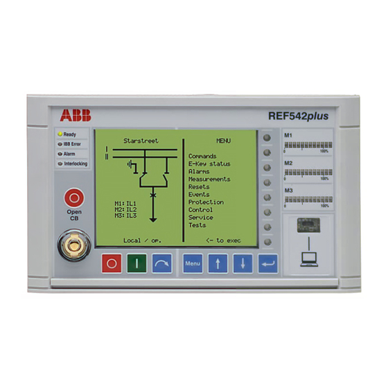
Page 13: Hmi Features
8 push buttons, several LEDs and an electronic key sensor. This new international HMI is a part of the product release of REF 542plus, starting from release 2.5. The resolution of the display is 320x240 (QVGA) and the display supports full Unicode character set. - Page 14 Control Key: this is dedicated to the control modes. It allows changing the operating mode of REF 542plus. The different operating modes discipline the access to the primary objects by the different REF 542plus interfaces (HMI and SCADA). When required, a Super User key to access both modes can be...
-
Page 15: Info And Menu Area
A051333 Fig. 3.2.-1 Info and Menu area Menu Navigation: these push buttons allow navigation trough the REF 542plus menus. Pressing this button, the unit goes back to the former menu. The up direction push button. - Page 16 Operating Tool. Infrared (IrDa) interface: This is the IrDa serial interface port to connect REF 542plus to a personal computer. By using the appropriate cable and the Operating Tool, the following actions are possible: Download a configuration into the unit.
-
Page 17: Ref 542Plus Status Information Area
LED is switched off when the auxiliary power is not present or when the unit is not operational (FUPLA is not running). IBB(interbaybus) Error. This LED is meaningful only when the REF 542plus is equipped with a communication module. When the configured communication module is detected the LED turns on to green. -
Page 19: Behavior At Power Up
Multifunction Protection and Switchgear Control Unit Operator's manual Behavior at power up Before energizing the switchgear, verify that the REF 542plus protection functions are properly set and that the unit is properly working (READY LED green). At power up, the HMI unit shows on the LCD for a few seconds the following: A051339 Fig. -
Page 21: Changing The Language Displayed
1MRS755869 REF 542plus REF 542plus Multifunction Protection and Switchgear Control Unit Operator's manual Changing the language displayed The international HMI version V5 can support up to two different languages. The first one can be used to display the local language. Due to the high QVGA resolution, it is possible to display, for example, Chinese on the HMI. - Page 22 Fig. 5.-2 Changing the language displayed on the HMI The former HMI of the REF 542plus (HMI Version V4) can still be applied together with the base unit having the new firmware of release 2.5. provided the firmware of the HMI is upgraded accordingly. After upgrading the firmware the HMI V4 behaves almost the same as the new international HMI V5.
- Page 23 1MRS755869 REF 542plus REF 542plus Multifunction Protection and Switchgear Control Unit Operator's manual display shall be changed, the relating language file must first be uploaded. After reset of the LCD the requested language will be displayed.
-
Page 25: Control Modes
1MRS755869 REF 542plus REF 542plus Multifunction Protection and Switchgear Control Unit Operator's manual Control modes 6.1. Available control modes Local Control It is possible to control the circuit breaker and other primary objects from the HMI using the object control buttons. Open and close operations are possible only if the interlocking logic programmed into the unit allow them. - Page 26 REF 542plus REF 542plus 1MRS755869 Multifunction Protection and Switchgear Control Unit Operator's manual A051340 Fig. 6.2.-1 Changing the control mode by using the control key...
-
Page 27: Operating The Primary Objects
Only primary objects controlled directly by REF 542plus can be selected. For example, REF 542plus will show the correct position of a manual disconnect switch after an operation, but it will not be possible to select it. -
Page 29: Viewing And Resetting Alarms
1MRS755869 REF 542plus REF 542plus Multifunction Protection and Switchgear Control Unit Operator's manual Viewing and resetting alarms 8.1. Viewing alarms The presence of an alarm, when latched, is indicated by the alarm LED turned on or by one of the 8 x 4 pages user programmable LED’s turned on to red. The conditions or the events that generate an alarm are defined and programmed with the Operating Tool. - Page 30 REF 542plus REF 542plus 1MRS755869 Multifunction Protection and Switchgear Control Unit Operator's manual Some alarms might not be reset before the cause that generated it has been removed. For example, an alarm due to an error in the tripping circuit (coil supervision) cannot be reset before the tripping coil is replaced.
-
Page 31: Viewing Measurements
Multifunction Protection and Switchgear Control Unit Operator's manual Viewing measurements REF 542plus offers complete measurements set to the user. To view the measurements, select the measurement menu with the navigation button. Use the UP and DOWN buttons to browse the measurement pages. - Page 32 REF 542plus REF 542plus 1MRS755869 Multifunction Protection and Switchgear Control Unit Operator's manual A051343 Fig. 9.-1 Measurements visualization The available measurements depend upon the analogue input module type and the unit configuration.
-
Page 33: Viewing Events
Operator's manual Viewing events REF 542plus records the last 30 protection events (start, trips, block and other). This internal memory is managed as a circular buffer, for example the 31st event overwrites the 1st oldest one. In case of a power loss, events are kept because they are stored in the non-volatile memory. -
Page 35: Viewing And Changing The Protection Settings
1MRS755869 REF 542plus REF 542plus Multifunction Protection and Switchgear Control Unit Operator's manual Viewing and changing the protection settings 11.1. Viewing the protection settings The protection functions currently installed in the unit can be seen in the menu protection functions. Select the menu protection functions with the navigation push buttons. -
Page 36: Changing The Protection Parameters
REF 542plus REF 542plus 1MRS755869 Multifunction Protection and Switchgear Control Unit Operator's manual The procedure to change the protection mode is identical to changing the control mode. At first, the menu E-Key must be selected. Then the protection key must be placed in the electronic key sensor. - Page 37 1MRS755869 REF 542plus REF 542plus Multifunction Protection and Switchgear Control Unit Operator's manual A051347 Fig. 11.2.2.-1 Changing protection parameters Press again to leave the protection functions menu. The unit will then ask what to do with the changes: The following screen will appear: A051348 Fig.
-
Page 38: Changing The Active Parameter Set
REF 542plus REF 542plus 1MRS755869 Multifunction Protection and Switchgear Control Unit Operator's manual Select the desired choice with Up or Down and then press ENTER confirm it. The meaning of the choices is as follows: Store permanently: The new parameters are stored in the unit internal memory. They will be used immediately and for all the next starts. -
Page 39: Viewing And Changing Control Parameters
1MRS755869 REF 542plus REF 542plus Multifunction Protection and Switchgear Control Unit Operator's manual 11.2.4. Viewing and changing control parameters Select the Control menu with the navigation push buttons and highlight the desired control function. Press ENTER to select it. Press again and the cursor will automatically go to the first control parameter. -
Page 41: Setting The Time And Date
1MRS755869 REF 542plus REF 542plus Multifunction Protection and Switchgear Control Unit Operator's manual Setting the time and date During commissioning, the internal time and date of the unit should be set to the current values. There are a few differences according to the unit configuration. - Page 42 REF 542plus REF 542plus 1MRS755869 Multifunction Protection and Switchgear Control Unit Operator's manual Usually, the SCADA transmits to the unit the time and date according to the used protocol services. There are some differences depending on the used protocol. IEC 60870–5–103 protocol: The IEC 60870–5–103 module is the time master.
-
Page 43: Command Page
Multifunction Protection and Switchgear Control Unit Operator's manual Command page From this page, it is possible to access the HMI command objects configured in the application software of REF 542plus. For more information on these objects, refer to Operating Tool user manual. A051352 Fig. 13.-1... -
Page 45: Ref 542Plus Commissioning Mode
REF 542plus commissioning mode The commissioning test mode allows accessing all the digital and analogue inputs and outputs of REF 542plus. This mode is independent of the REF 542plus application. This working mode has been designed to make easier the wiring verification. -
Page 46: Binary Input Commissioning Page
REF 542plus REF 542plus 1MRS755869 Multifunction Protection and Switchgear Control Unit Operator's manual A051353 Fig. 14.-1 Commissioning mode display 14.1. Binary input commissioning page This page displays the current status of the binary input channels on the binary IO modules. There are 14 binary inputs per module available. For the binary inputs numbering see Section 19.2. -
Page 47: Binary Output Commissioning Page
1MRS755869 REF 542plus REF 542plus Multifunction Protection and Switchgear Control Unit Operator's manual A051354 Fig. 14.1.-1 Binary inputs commissioning page 14.2. Binary output commissioning page On this page, it is possible to force the status of the binary outputs. All the outputs can be driven with the exception of the watchdog. -
Page 48: Analog Input Commissioning Page
REF 542plus REF 542plus 1MRS755869 Multifunction Protection and Switchgear Control Unit Operator's manual A051355 Fig. 14.2.-1 Binary outputs commissioning page 14.3. Analog input commissioning page This page shows the analog measurements acquired by the analog input module. The shown values are independent on the rated primary current or voltage of the primary sensors. - Page 49 1MRS755869 REF 542plus REF 542plus Multifunction Protection and Switchgear Control Unit Operator's manual “Channel descriptor” “Channel number “: “Values” Line description: Channel descriptor: Analog input Channel number: x, where x addresses the analog input channel. CT (1-5 A) → Rated secondary current related to the current input.
-
Page 50: Analog Output 4- 20 Ma Commissioning Page
REF 542plus REF 542plus 1MRS755869 Multifunction Protection and Switchgear Control Unit Operator's manual A051357 Fig. 14.3.-2 Analog inputs commissioning page for the 6 sensor module connected to 3 voltage divider and 3 Rogowski coils 14.4. Analog output 4- 20 mA commissioning page This page allows setting the value of the analog channels in the 4-20 mA module. -
Page 51: Analog Input 4-20 Ma Commissioning Page
1MRS755869 REF 542plus REF 542plus Multifunction Protection and Switchgear Control Unit Operator's manual A051358 Fig. 14.4.-1 A 4-20 mA analog outputs commissioning page 14.5. Analog input 4-20 mA commissioning page From this page, it is possible to read the analog measurements of the Analog Input 4-20 mA module. -
Page 52: Optical Inputs Commissioning Page
REF 542plus REF 542plus 1MRS755869 Multifunction Protection and Switchgear Control Unit Operator's manual “Channel descriptor” “Channel number “: “Values” Line description: General 4-20 mA sensor → General sensor Channel descriptor: Trafag → Density, Temperature Channel number: x. Where x addresses the analog input channel. -
Page 53: Optical Output Commissioning Page
1MRS755869 REF 542plus REF 542plus Multifunction Protection and Switchgear Control Unit Operator's manual A051360 Fig. 14.6.-1 Optical inputs commissioning page 14.7. Optical output commissioning page This page allows driving the optical output on the main module (only type 1VCF751021R801). “Channel descriptor” “Channel number “: “Values”... - Page 54 REF 542plus REF 542plus 1MRS755869 Multifunction Protection and Switchgear Control Unit Operator's manual A051361 Fig. 14.7.-1 Optical output commissioning page...
-
Page 55: Connection To Pc
Infrared (IrDa) to RS232 converter cable A special cable with an optical infrared (IrDa) interface is needed to connect REF 542plus to a serial port of a PC. This cable is available from ABB. Fig. 15.1.-1 REF 542plus serial cable with optical infrared (IrDa) interface A060412 Fig. -
Page 56: Downloading A Configuration
When the connection is set up with the appropriate cable, it is possible to download the configuration into REF 542plus with the Operating Tool. Connect the infrared (IrDa) converter to the foreseen connector on the HMI and the D-sub connector to the PC. -
Page 57: Serial Port Settings
1MRS755869 REF 542plus REF 542plus Multifunction Protection and Switchgear Control Unit Operator's manual 15.3.1. Serial port settings A051364 Fig. 15.3.1.-1 Setting the communication parameter of the serial port Select the COM port where the RS232/Infrared (IrDa) cable or RS232 null-modem cable is plugged in. - Page 58 REF 542plus REF 542plus 1MRS755869 Multifunction Protection and Switchgear Control Unit Operator's manual Baud rate 19,200 Data bits Stop bits Parity Even After the download of the configuration file using the service or the debug port, press ENTER key on the PC keyboard to end the download process.
- Page 59 REF 542plus is fully operational during the download. After the download, REF 542plus starts to write the new configuration in the non-volatile with a low priority task in background. This task might take several seconds. Do not switch off Base Unit power supply during the storing. The whole unit configuration might be corrupted and a new configuration download might be necessary.
-
Page 60: Uploading The Configuration
15.4. Uploading the configuration With the Operating Tool, it is possible to upload the current configuration inside REF 542plus. Set the Operating Tool and the PC as for the download and click the menu Transfer/load from REF 542plus. Please note: The uploaded configuration overwrites the current one inside the Operating Tool. -
Page 61: Troubleshooting
1MRS755869 REF 542plus REF 542plus Multifunction Protection and Switchgear Control Unit Operator's manual Troubleshooting 16.1. Error messages Base Unit not responding, communication corrupted or wrong slave address When the HMI is not able to communicate with the Base Unit, the following... - Page 62 REF 542plus REF 542plus 1MRS755869 Multifunction Protection and Switchgear Control Unit Operator's manual Power Up Operations After pressing the key the Power Up Operation menu is shown as in the following Fig. 16.1.-2. A051437 2 Fig. 16.1.-2 Menu for Power Up Operations for HMI V5...
- Page 63 1MRS755869 REF 542plus REF 542plus Multifunction Protection and Switchgear Control Unit Operator's manual A051438 2 Fig. 16.1.-4 HMI is polling the Base unit addresses Select the HMI <-> Base Unit address to change the address to be polled. A051439 2 Fig.
- Page 64 Operator's manual A051440 2 Fig. 16.1.-6 HMI test page Base Unit not configured REF 542plus is without configuration when the following message appears: A051441 2 Fig. 16.1.-7 REF 542plus without configuration Solution: Download the configuration into the unit by using the serial cable and the Operating Tool.
- Page 65 Multifunction Protection and Switchgear Control Unit Operator's manual A051442 2 Fig. 16.1.-8 REF 542plus configuration is not stored in the unit internal memory Solution: Try to download the configuration again. If after two or three attempts the error remains, contact ABB.
-
Page 66: Clearing The Configuration Inside The Unit
In some cases, there might be the need to delete the configuration stored inside the REF 542plus. For example, when the RED alarm is on, it is not possible to download a new configuration inside REF 542plus. The following procedure deletes... -
Page 67: Primary Objects Incorrect Visualization
Operator's manual 16.3. Primary objects incorrect visualization The primary object status is usually acquired by REF 542plus with 2 distinct contacts, one that is closed when the object is closed and another one that is opened when the object is opened. - Page 68 REF 542plus REF 542plus 1MRS755869 Multifunction Protection and Switchgear Control Unit Operator's manual Note: When the primary object in such an undefined positions, issuing an open command will activate the open coil on the circuit breaker. The open operation is never blocked.
-
Page 69: Terminology
Multifunction Protection and Switchgear Control Unit Operator's manual Terminology Term Description Ethernet Physical communication network to transfer Internet data of the REF 542plus to the PC and back. Modbus By extension, communication board implementing the Modbus protocol for REF 542plus. -
Page 71: Abbreviations
Liquid crystal display Logical device Light-emitting diode Local operating network Micro controller Personal computer Random access memory SCADA Supervision, control and data acquisition Single-line diagram SNTP Simple Network Time Protocol Data communication protocol developed by ABB Transmission Control Protocol Voltage transformer... -
Page 73: Appendix A: Connection Diagrams
Operator's manual Appendix A: Connection diagrams The pictures below show the connections plate for REF 542plus both in the wide and standard housing versions. The wide housing version can house three binary input and output modules; the communication module, the analog output module or alternatively the analog 4-20 mA input module. - Page 74 REF 542plus REF 542plus 1MRS755869 Multifunction Protection and Switchgear Control Unit Operator's manual A051447 Fig. 19.-2 REF 542plus standard housing connections plate with mixed analog input connector Table 19.-1 summarizes the connectors. Table 19.-1 Connectors Connector Meaning Base Unit power supply...
-
Page 75: Analog Inputs
Sensor 8 19.1. Analog Inputs REF 542plus can have a maximum of 8 analog input channels. These inputs are divided into three measurement groups: Measurement Group 1: channel 1, channel 2, channel 3 Measurement Group 2: channel 4, channel 5, channel 6... - Page 76 REF 542plus REF 542plus 1MRS755869 Multifunction Protection and Switchgear Control Unit Operator's manual The Rogowsky coil can be used for current sensing. The correct ratio of the Rogowsky coil is selected with the Operating Tool. The resistive divider can be used for voltage sensing.
- Page 77 1MRS755869 REF 542plus REF 542plus Multifunction Protection and Switchgear Control Unit Operator's manual T8/1 T4/3 T2/B T2/2 T6/3 T7/B T7/2 T7/A T4/B T4/2 T2/3 T6/B T6/2 T7/R T7/3 T7/B T4/R T4/1 T2/R T2/1 T6/R T6/1 T7/1 B: Black wire for voltage transformer.
-
Page 78: Binary Inputs And Outputs
X30 (inputs), X31 (outputs) for the second module. X40 (inputs), X41 (outputs) for the third module, available with the wide housing only. REF 542plus can be equipped with two different types of binary inputs and outputs modules: static or with electromechanical relays. 19.2.1. -
Page 79: Electromechanical
Electromechanical In the electromechanical module, digital inputs are implemented with optocouplers and digital outputs are implemented with electromechanical relays. REF 542plus can be equipped with electromechanical module type BIO3. 19.2.2.1. BIO3 Twelve different types of BIO3 are available depending upon the supply voltage and other features. -
Page 80: Other Connections
REF 542plus REF 542plus 1MRS755869 Multifunction Protection and Switchgear Control Unit Operator's manual BIO3 Code Description 1VCF750132R0804 Binary I/O3 - 80..250 VDC/50 VDC Standard with Static Channel 1VCF750132R0802 Binary I/O3 - 80..250 VDC/50 VDC Standard with interconnected '-' on inputs 1VCF750132R0804 Binary I/O3 - 80..250 VDC/50 VDC Standard with... -
Page 81: Analog Inputs 4-20 Ma
1MRS755869 REF 542plus REF 542plus Multifunction Protection and Switchgear Control Unit Operator's manual A051457 Fig. 19.3.1.-1 0/4-20 mA analog outputs (Version 2.x since 06/2006) 19.3.2. Analog inputs 4-20 mA When present, the 4-20 mA analog input module uses connector X50. Sensor’s connections are shown in Fig. -
Page 82: Communication Module
REF 542plus REF 542plus 1MRS755869 Multifunction Protection and Switchgear Control Unit Operator's manual A051458 Fig. 19.3.2.-1 4-20 mA analog inputs Only passive sensors, for example those that are powered from the loop can be connected to the 4…20 mA analog input module. -
Page 83: Hmi
1MRS755869 REF 542plus REF 542plus Multifunction Protection and Switchgear Control Unit Operator's manual 19.3.6. A051459 Fig. 19.3.6.-1 HMI connectors Fig. 19.3.6.-1 shows the back side of the HMI. The connector for the HMI power supply is X10, which is located on the right-hand side of the Fig. 19.3.6.-1. The serial cable for the connection to the base unit is to place on the other connector X20 on the left-hand side. -
Page 85: Appendix B: Menu Structure
Reset page From this page, it is possible to reset alarms and other quantities. Some reset actions are possible only if REF 542plus is in the proper mode. The possibility of reset in the different submenus is described in the following:... - Page 86 REF 542plus REF 542plus 1MRS755869 Multifunction Protection and Switchgear Control Unit Operator's manual Reset alarm: the LED's alarm indication can be reset in this submenu, independent of the active mode A051461 Fig. 20.2.-1 Attempt to resetting the fault recorder in the wrong mode...
-
Page 87: Protection
1MRS755869 REF 542plus REF 542plus Multifunction Protection and Switchgear Control Unit Operator's manual Reset alarm: can only be reset, if there is no active alarm present anymore. An attempt to reset an alarm caused for example by an interrupted open coil is impossible as long as the coil is not replaced. -
Page 88: Statistics
REF 542plus REF 542plus 1MRS755869 Multifunction Protection and Switchgear Control Unit Operator's manual A051463 Fig. 20.6.-1 Service page menu The service page contains the following submenus. 20.6.1. Statistics This submenu shows the FUPLA cycle time and other information related to the current configuration in the unit. -
Page 89: Hardware Identification
A051465 Fig. 20.6.2.-1 Versions submenu 20.6.3. Hardware identification This submenu shows the reference information of the hardware modules installed into REF 542plus. A051466 Fig. 20.6.3.-1 Hardware identification Hardware information page To display the information select the row and press ENTER . - Page 90 REF 542plus REF 542plus 1MRS755869 Multifunction Protection and Switchgear Control Unit Operator's manual A051467 Fig. 20.6.3.-2 Hardware information page When the information from the module is not available the following page is displayed. A051468 Fig. 20.6.3.-3 Hardware information is not available When the information stored on the module is corrupted, the following page is displayed.
-
Page 91: Communication
When the module is not present or the module is not able to publish the HW identification data, the following page is displayed. A051470 Fig. 20.6.3.-5 Hardware information not available 20.6.4. Communication This subpage displays the information related to the communication ports available and configured in REF 542plus. -
Page 92: Iec 103 Communication Page
REF 542plus REF 542plus 1MRS755869 Multifunction Protection and Switchgear Control Unit Operator's manual A080290 Fig. 20.6.4.-1 Communication subpage visualization When the port is not installed or configured, the following page will be displayed. A051642 Fig. 20.6.4.-2 Communication module is not installed 20.6.4.1. - Page 93 1MRS755869 REF 542plus REF 542plus Multifunction Protection and Switchgear Control Unit Operator's manual A051645 Fig. 20.6.4.1.-1 IEC 103 communication module page In this subpage, it is possible to block the monitoring direction of the module. For more information, refer to the Communication Module User Manual.
-
Page 94: Lon Communication Page
REF 542plus REF 542plus 1MRS755869 Multifunction Protection and Switchgear Control Unit Operator's manual A051647 Fig. 20.6.4.1.-3 IEC 103 communication module test mode subpage 20.6.4.2. LON communication page When the COM-L module for LON communication is installed and active, the following page displays the configured Node ID. -
Page 95: Spa Communication Page
1MRS755869 REF 542plus REF 542plus Multifunction Protection and Switchgear Control Unit Operator's manual 20.6.4.3. SPA communication page When the SPA bus communication module is installed, the following page is displayed. A051648 Fig. 20.6.4.3.-1 SPA bus communication module page It is not possible to modify the SPA bus slave address of the unit on this page. -
Page 96: Can Communication Page
20.6.4.5. CAN communication page When the CAN port has been enabled the following pages display the CAN communication settings. The CAN communication may only be used by ABB switchgear companies. A051649 Fig. 20.6.4.5.-1 CAN communication port page Only channel 1 is currently available. - Page 97 1MRS755869 REF 542plus REF 542plus Multifunction Protection and Switchgear Control Unit Operator's manual A051650 Fig. 20.6.4.5.-2 CAN communication port subpage CAN INFO subpage This page displays the CAN status information. A051651 Fig. 20.6.4.5.-3 CAN communication port subpage CAN Commands subpage From this page, it is possible to issue direct operation to the CAN communication subsystem.
- Page 98 A051652 Fig. 20.6.4.5.-4 CAN communication port subpage CAN setting subpage In this page, it is possible to change the node address of the CAN communication. This setting is allowed only when the REF 542plus node is in the Pre-Operational status.
-
Page 99: Hmi Communication Page
1MRS755869 REF 542plus REF 542plus Multifunction Protection and Switchgear Control Unit Operator's manual A051653 Fig. 20.6.4.5.-5 CAN communication port subpage 20.6.4.6. HMI communication page In this page, it is possible to change the Base Unit slave address used to communicate with the HMI. -
Page 100: Ethernet Ip Page
REF 542plus REF 542plus 1MRS755869 Multifunction Protection and Switchgear Control Unit Operator's manual A051654 Fig. 20.6.4.6.-1 HMI, changing Base Unit address to be polled 20.6.4.7. Ethernet IP page This page shows the current settings of the Ethernet communication subsystem. Here, it is possible to visualize the IP and MAC address. The IP and MAC addresses cannot be changed from this page. -
Page 101: Ethernet Communication Page
1MRS755869 REF 542plus REF 542plus Multifunction Protection and Switchgear Control Unit Operator's manual 20.6.4.8. Ethernet communication page When the Ethernet module is applied, the following subpages appear after you select the corresponding Ethernet communication submenu, depending on the actual condition. The following Fig. 20.6.4.8.-1 shows a case where the Ethernet board is... - Page 102 REF 542plus REF 542plus 1MRS755869 Multifunction Protection and Switchgear Control Unit Operator's manual A070399 Fig. 20.6.4.8.-2 Subpage if Ethernet board is not installed In normal situation where the Ethernet module is installed, the following subpage appears when you select another submenu, as shown in Fig. 20.6.4.8.-3: A080292 Fig.
- Page 103 General Settings subpage The General Settings subpage displays the configuration parameters coming from the REF 542plus main module, whereas the General Info subpage displays the status values and configurations coming from the Ethernet communication module. The following two figures, Fig. 20.6.4.8.-4 and Fig. 20.6.4.8.-5, show the related subpages.
- Page 104 REF 542plus REF 542plus 1MRS755869 Multifunction Protection and Switchgear Control Unit Operator's manual A080296 Fig. 20.6.4.8.-5 General Info subpage To move from one subpage to another click the UP , and DOWN buttons. You can go back to the FB COM Ethernet page from each subpage by clicking the MENU button.
- Page 105 1MRS755869 REF 542plus REF 542plus Multifunction Protection and Switchgear Control Unit Operator's manual A080298 Fig. 20.6.4.8.-6 TCP/IP Settings subpage for port 1 A080300 Fig. 20.6.4.8.-7 TCP/IP INFO subpage for port 1 At the moment, you can either use port 1 or port 2. If you apply port 2 , the subpages...
- Page 106 REF 542plus REF 542plus 1MRS755869 Multifunction Protection and Switchgear Control Unit Operator's manual A080302 Fig. 20.6.4.8.-8 TCP/IP Settings subpage for port 2 A080304 Fig. 20.6.4.8.-9 TCP/IP INFO subpage for port 2 SNTP subpage The SNTP subpage displays whether SNTP is enabled or disabled.
- Page 107 1MRS755869 REF 542plus REF 542plus Multifunction Protection and Switchgear Control Unit Operator's manual A080306 Fig. 20.6.4.8.-10 SNTP disabled If SNTP is enabled, the related subpage consists of two different subpages, as shown in the following two figures Fig. 20.6.4.8.-11 and Fig. 20.6.4.8.-12.
- Page 108 REF 542plus REF 542plus 1MRS755869 Multifunction Protection and Switchgear Control Unit Operator's manual A080310 Fig. 20.6.4.8.-12 SNTP INFO subpage You can move from one subpage to another by clicking the UP , and DOWN buttons. You can go back to the FB COM Ethernet subpage by clicking the MENU button.
- Page 109 1MRS755869 REF 542plus REF 542plus Multifunction Protection and Switchgear Control Unit Operator's manual A080312 Fig. 20.6.4.8.-13 Protocols subpage for IEC61850 The following figure 20.6.4.8.-14shows the Protocols subpage for MODBUS TCP protocol. A080314 Fig. 20.6.4.8.-14 Protocols subpage for MODBUS TCP The pages shown when the protocol is currently disabled are presented in 20.6.4.8.-...
-
Page 110: Char Map
REF 542plus REF 542plus 1MRS755869 Multifunction Protection and Switchgear Control Unit Operator's manual A080316 Fig. 20.6.4.8.-15 Protocols subpage in case of IEC61850 disabled A080318 Fig. 20.6.4.8.-16 Protocols subpage in case of MODBUS TCP disabled 20.6.5. Char map This page shows the active char map used by the HMI. Refer to the Operating Tool... -
Page 111: Lcd Contrast
20.6.7. Load flow direction The load flow direction determines how REF 542plus computes energy and power. It is set with the Operating Tool and it is also dependent upon the current and voltage transformers (or sensors) connections in the primary parts. -
Page 112: Test Page
HMI buttons are not available during the test. The displayed information on the HMI does not reflect the switchgear’s actual status. REF 542plus is protecting the switchgear during the HMI test. The HMI test takes a few seconds. -
Page 113: Test Primary Object
1MRS755869 REF 542plus REF 542plus Multifunction Protection and Switchgear Control Unit Operator's manual A051659 Fig. 20.7.1.-1 Test page menu 20.7.2. Test primary object The circuit breaker and other switching devices can be tested from this submenu. The object control buttons are used to perform the desired tests. A warning message is displayed before leaving the test primary object mode. -
Page 115: Appendix C: Tripping Time Indication
1MRS755869 REF 542plus REF 542plus Multifunction Protection and Switchgear Control Unit Operator's manual Appendix C: Tripping time indication The example below shows and explains the information on the Events page of the HMI. It refers to events generated by Overcurrent Instantaneous protection function. -
Page 117: Appendix D: Self Supervision
Level 1 faults are irrecoverable fatal errors. After fault detection, the system is not able to guarantee safe execution of the protection and control functions. The irrecoverable fault forces REF 542plus to stop any activities and it can only be restarted after a power-switch cycle (power off/on) or after a configuration download (if possible). - Page 118 SPA event Supervision by bootloader REF 542plus has an on-chip bootloader that handles the software upgrade and the entering into Factory test mode. The bootloader supervises RAM (Random Access Memory) and FLASH (MC non-volatile memory) application program correctness.
- Page 119 If the fault is not reproducible, a special REF 542plus SW can be built that is able to make a trace log of all the activities executed by the SW (interrupts, tasks switching, events, semaphore, etc.).
- Page 120 Fatal errors Fatal errors are faults detected by the internal error checking functionality that, if it fails, compromises the system reliability (e.g. RTOS errors). The REF 542plus fatal error handler stores a fatal error description string in the internal memory.
- Page 121 Operator's manual Note that all version checks are performed by REF542CONF before configuration download. Therefore, the fault can occur only after a REF 542plus firmware upgrade/downgrade or after FLASH configuration data corruption. The following table describes signalling/handling of the configuration faults:...
- Page 122 DSP communication COM module (optional extension) The COM module is an optional module that can be installed in the REF 542plus housing. Its supervision is done only if the COM module is detected at start-up or configured by REF542CONF. The supervision verifies correct COM module configuration start-up and correct COM working status during normal operation.
- Page 123 AI20mA module (optional extension) The AI20mA (20 mA analogue input module) is an optional module that can be installed in the REF 542plus housing. Its supervision is done only if the AI20mA module is detected at start-up or configured by REF542CONF. The supervision verifies correct AI20mA start-up and correct AI20mA working status during normal operation.
- Page 124 SPA event “102E54” (command failure) FLASH data REF 542plus uses a FLASH device to store non-volatile data/configuration. The MC supervises every FLASH erase/write operation checking that the FLASH status registers. In order to protect the FLASH data against erroneous write/erase attempts, the FLASH is write-protected which means that erroneous access will raise a SW exception (address error).
- Page 125 1MRS755869 REF 542plus REF 542plus Multifunction Protection and Switchgear Control Unit Operator's manual Faults/Errors Signalling Level SPA event “102E1” Memory full error SPA event “102E2” Ready error SPA event “102E3” Writing byte error SPA event “102E4” Block erase error SPA event “102E5”...
-
Page 127: Appendix E: Telnet Protocol
1MRS755869 REF 542plus REF 542plus Multifunction Protection and Switchgear Control Unit Operator's manual Appendix E: Telnet protocol Through the Telnet protocol it is possible to access an Ethernet module from a specific computer connected remotely to the same network. Telnet provides... - Page 128 REF 542plus REF 542plus 1MRS755869 Multifunction Protection and Switchgear Control Unit Operator's manual A070411 Fig. 23.-2 Running a ping test In the example above, the PC sends a ping command to an Ethernet board connected to the net with the address 192.168.2.106. If the connection is correct, the following...
- Page 129 1MRS755869 REF 542plus REF 542plus Multifunction Protection and Switchgear Control Unit Operator's manual A070414 Fig. 23.-5 Log into the Telnet shell A connection with the Ethernet board Telnet server is now established. The Ethernet module Telnet server allows different logging levels to enable different functions and commands.
- Page 130 REF 542plus REF 542plus 1MRS755869 Multifunction Protection and Switchgear Control Unit Operator's manual shows the configuration parameters of the ports: topology protocol type MAC address (for port1 and port2) IP address (for port1 and port2) subnet mask (for port1 and port2)
- Page 131 1MRS755869 REF 542plus REF 542plus Multifunction Protection and Switchgear Control Unit Operator's manual shows the Modbus TCP configuration shows current connections' states and statistics for Modbus TCP server Finally, the section Time configuration and state collects following commands: shows possible time sources and current time...
- Page 134 ABB Oy Distribution Automation P.O. Box 699 FI-65101 Vaasa FINLAND +358 10 22 11 +358 10 22 224 1094 http://www.abb.com/substationautomation...