Table of Contents
Advertisement
Quick Links
Advertisement
Chapters
Table of Contents

Related Manuals for ABB FSPS-21


Summary of Contents for ABB FSPS-21
- Page 1 — OPTIONS FOR ABB DRIVES FSPS-21 safety functions fieldbus module User's manual...
- Page 3 FSPS-21 safety functions fieldbus module User's manual Table of contents 1. Safety instructions 8. Mechanical installation 9. Electrical installation 17. Start-up © 2019 ABB Oy. All Rights Reserved. 3AXD50000158638 Rev A EFFECTIVE: 2019-02-01...
-
Page 5: Table Of Contents
Intentional misuse ................Safety-related parts ................Limitations of Safe torque off (STO) function ..........Overall system stopping performance ............4 Overview of the FSPS-21 module and the Ethernet network Contents of this chapter ................Module overview .................. Diagnostics ..................Fault reaction function .............. - Page 6 9 Electrical installation Contents of this chapter ................Necessary tools and instructions ............... General cabling instructions ..............Connecting the FSPS-21 to the Ethernet network and to the STO of the drive ..Terminals ..................10 Installation checklists Contents of this chapter ................
- Page 7 Warnings ................... Drive configuration ................PROFINET IO connection configuration ........... FSPS-21 configuration parameters – group A (group 1) ......FSPS-21 configuration parameters – group B (group 2) ......FSPS-21 configuration parameters – group C (group 3) ......Control locations ................
- Page 8 Contents of this chapter ................PROFINET IO ..................PROFINET network settings ..............PROFINET IO in FSPS-21 ..............The services provided by the FSPS-21 module ..........Cyclic message types ................PPO types ..................Standard telegram (ST) types (DP-V1) ............ Behavior of output data ...............
- Page 9 Parameters for the PROFINET and PROFIsafe communication ....Configuring the safety PLC ..............Downloading the GSD file ..............Configuring the ABB AC500-S Safety PLC ..........Monitoring the PROFIsafe message ............ Configuring FSPS-21 with TIA14 ............Configuring the Siemens SIMATIC Fail-safe S7 PLC ........
- Page 10 Replacing the FSPS-21 module ............Drive replacement ................Reinstalling the FSPS-21 module to another drive ........Drive firmware update ................Updating the firmware of the drive where the FSPS-21 module is installed ..Updates .................... Proof tests ..................Decommissioning .................
-
Page 11: Table Of Contents
Table of contents 11 Further information... -
Page 13: Safety Instructions
Safety instructions 13 Safety instructions Contents of this chapter The chapter contains the warning symbols used in this manual and the safety instructions which you must obey when you install or connect an option module. If you ignore the safety instructions, injury, death or damage can occur. -
Page 14: Safety In Installation And Maintenance
14 Safety instructions Safety in installation and maintenance These instructions are for all who install or connect an option module to a unit and need to open its front cover or door to do the work. WARNING! Obey these instructions. If you ignore them, injury or death, or damage to the equipment can occur. -
Page 15: Introduction To The Manual
Introduction to the manual 15 Introduction to the manual Contents of this chapter This chapter introduces this manual. Applicability This manual applies to the FSPS-21 safety functions fieldbus module, revision A. Compatibility ■ Drives The FSPS-21 safety fieldbus module is compatible with: •... -
Page 16: Plcs
Purpose of the manual The manual explains how to install the FSPS-21 module and configure and commission the supported safety functions. It describes how to meet and maintain safety life cycle requirements of the FSPS-21 module to ensure required safety performance and specified safety integrity. -
Page 17: Exclusion Of Liability
Exclusion of liability ABB is not responsible for the implementation, verification and validation of the overall safety system. It is the responsibility of the system integrator (or other party) who is responsible for the overall system and system safety. -
Page 18: Certificates
SIL capability valid. The same interval must be followed to keep the PL capability (EN ISO 13849) valid. Note that any T1 values given cannot be regarded as a guarantee or warranty. Certificates The valid TÜV and PROFIsafe certificates can be found at the ABB library (www.abb.com/drives/documents). -
Page 19: Related Manuals
3AUA0000085967 ACS580 standard control program firmware manual 3AXD50000016097 ACS380 machinery control program firmware manual 3AXD50000029275 Option manuals FSPS-21 safety functions fieldbus module user's manual 3AXD50000158638 ACX-AP-x assistant control panels user’s manual 3AUA0000085685 ACS-BP-S Basic control panel user's manual 3AXD50000032527 Manuals and quick guides for I/O extension modules, fieldbus adapters, etc. - Page 20 20 Introduction to the manual You can find manuals and other product documents in PDF format on the Internet. See www.abb.com/drives/documents. For manuals not available in the Document library, contact your local ABB representative. For additional ABB safety information and solutions visit http://www.abb.com/safety.
-
Page 21: Safety System Information And Considerations
Meeting the requirements of the Machinery Directive If the machine, where the FSPS-21 module is part of a safety system, is going to be sold or taken into use in Europe, it is the responsibility of the machine builder / OEM / system... -
Page 22: Responsibilities
If you detect any failure in safety functions, contact your local ABB representative. Intentional misuse Use the safety module according to the instructions given in the user’s manual. ABB is not responsible for any damage caused by the misuse of the module. -
Page 23: Overview Of The Fsps-21 Module And The Ethernet Network
ACS380 which enables the connection of the drive to an Ethernet network and a safety PLC. The intended use of the FSPS-21 safety option module is to safely stop the PDS(SR) (VSD, drive). The module provides two safety functions, STO and SS1-t, which are activated via PROFIsafe over PROFINET. -
Page 24: Diagnostics
117). ■ Automatic acknowledgement FSPS-21 only has an automatic acknowledgement method for a safety function. This means that when the safety function request is removed, the FSPS-21 automatically enters the Operational state. Automatic acknowledgement also takes place during module start-up. - Page 25 Overview of the FSPS-21 module and the Ethernet network 25 Star topology Other PN-IO ABB drive Other PN-IO device device Switch or router Daisy chain topology using integrated Ethernet switch ABB drive ABB drive Other PN-IO ABB drive device Switch or router...
-
Page 27: Safety Functions
The STO function brings the machine safely into a no-torque state and/or prevents it from starting accidentally. The STO function in the FSPS-21 module activates the drive STO function, that is, opens the STO circuit in the drive. This prevents the drive from generating the torque required to rotate the motor. -
Page 28: Ss1 With Time Monitoring
Drive parameters related to safety functions (page 43) for more information. The FSPS-21 module monitors the stop ramp with a time limit. If the motor speed does not reach the user-defined zero speed limit within the specified time limit, the module activates the drive STO function, the motor coasts to a stop, and FSPS-21 creates a fault (0x7aa0). -
Page 29: Priorities Of Safety Functions
Safety functions 29 Note: The failure of deceleration initiated by SS1-t cannot be prevented by FSPS-21. Motor speed Time SS1 request Drive STO state & indication SS1 state & indication SS1-t delay for STO: Time after which the module activates the drive STO function regardless of the motor speed. -
Page 30: Acknowledgement Methods
States and modes ■ States When the FSPS-21 module is up and running, it can be in one of the following states depending on the drive STO status: • Safe: STO active, that is, the drive STO circuit is open, modulation stops, and motor coasts. -
Page 31: Hardware Description
1. Connect the network cable to connector [X1] on the module. 2. If you want to create a daisy chain network with the FSPS-21 mo first module to connector [X1] on the next module, and so on. 3. Connect the STO cable to the FSPS-21 module (black connector... -
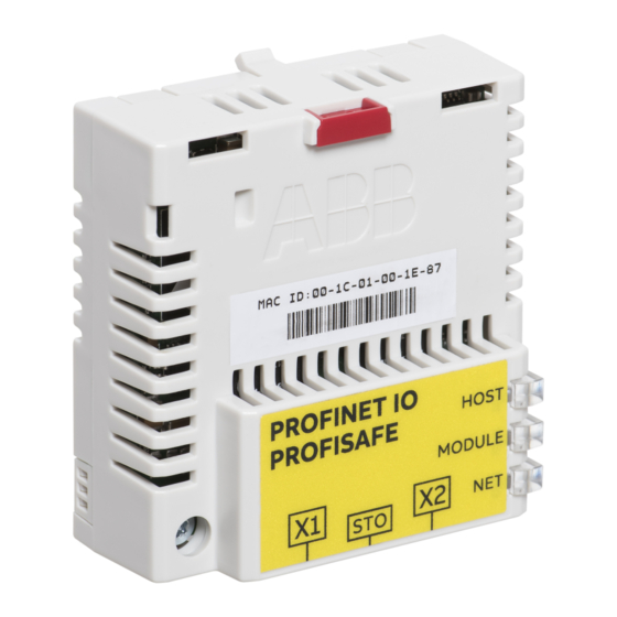
Page 32: Type Designation Label
WW: Manufacturing week: 01, 02, … for week 1, week 2, … SSSS: Integer starting every week from 0001 WS: Manufacturing location ABB MRP code of the FSPS-21 module Combined ABB MRP code, component revision, serial number and manufacturing location RoHS mark... -
Page 33: Planning For Installation
Technical data). The FSPS-21 module must only be used in an environment where no conductive dust or contaminants are present. One way to ensure proper protection against contamination is to use the FSPS-21 module in at least an IP54 enclosure. For further information on environmental limits, see chapter Planning the mechanical installation in the drive hardware manual. -
Page 34: Electrical Installation
34 Planning for installation Electrical installation ■ General requirements Electrical installation of the safety system must be performed according to the practices outlined in chapter Planning the electrical installation in the drive hardware manual. Chapter Installation checklists (page 41) provides additional advice for the planning. All wiring must be well protected, routed and clamped where practicable. -
Page 35: Mechanical Installation
This chapter contains a delivery checklist and instructions on installing the module. Necessary tools and instructions You will need a Torx TX10 screwdriver to secure the FSPS-21 module to the drive. See also the drive hardware manual. Unpacking and examining the delivery 1. -
Page 36: Installing The Module
Note: FSPS-21 is an option for inverter units only. In drives with separate supply and inverter units, FPNO-21 or FENA-21 module must be used for fieldbus communication in the supply unit. - Page 37 ou ignore them, injury or death, or damage to the Mechanical installation 37 3. Push in the lock. 4. Tighten the screw to torque 0.8 N·m using a Torx TX10 screwdriver. WARNING! Do not use excessive force, or leave the screw too loose. Overtightening can damage the screw or module.
-
Page 39: Electrical Installation
Electrical installation 39 Electrical installation Contents of this chapter This chapter contains general cabling instructions and instructions on connecting the FSPS-21 module to the Ethernet network and the drive. Necessary tools and instructions See the drive hardware manual. General cabling instructions •... -
Page 40: Terminals
2. If you want to create a daisy chain network with the FSPS-21 modules, co 2. If you want to create a daisy chain network with the FSPS-21 modules, connect connector [X2] of the 4. ACS880: Connect the yellow connector to drive’s STO connector. ACS380/580: Remove first module to connector [X1] on the next module, and so on. -
Page 41: Installation Checklists
Contents of this chapter This chapter contains a checklist for checking the mechanical and electrical installation of the FSPS-21 module and refers to common cause failure checklists in standards. Checklists Check the mechanical and electrical installation of the module before start-up. Go through the checklists below together with another person and make a memo as needed. -
Page 43: Configuration
We recommend our training courses on the FSPS-21 module in ABB MyLearning portal. Tools You need a control panel or the Drive composer PC tool to configure the FSPS-21 module. For more information, see Drive composer start-up and maintenance PC tool user's manual (3AUA0000094606 [English]) or a control panel user's manual. -
Page 44: Configuring The Fsps-21
51.24 PROFIsafe destination address Sets the PROFIsafe destination address, that is, the individual address of the FSPS-21 module in the safety communication network. Note: This address must be the same as is set in the F-Paramet- ers for the PROFIsafe module properties (F_Dest_Add). - Page 45 1. Plan the configuration according to the application requirements. 2. Set the drive parameters related to PROFINET IO and PROFIsafe communication, see FSPS-21 configuration parameters – group A (group 1) (page 48). 3. Set the drive parameters related to safety functions, see...
-
Page 47: Profinet Io - Start-Up
Warnings WARNING! Obey the safety instructions given in this manual and the drive documentation. Drive configuration The information in this section applies to all drive types compatible with the FSPS-21 module, unless otherwise stated. ■ PROFINET IO connection configuration After the adapter module has been mechanically and electrically installed, you must prepare the drive for communication with the module. -
Page 48: Fsps-21 Configuration Parameters - Group A (Group 1)
The new parameter settings take effect only when you power up the module the next time or when you activate the fieldbus adapter refresh parameter. FSPS-21 configuration parameters – group A (group 1) Note: The actual parameter group number depends on the drive type. Group A (group 1) corresponds to: •... - Page 49 PROFINET IO – Start-up 49 Name/Value Description Default IP configuration Sets the method for configuring the IP address, subnet 0 = Static IP mask and gateway address for the module. In a PROFINET IO network, the master controller has a Duplicate Address Detection mechanism. Note: It is recommended to use IP setting for PROFINET as Static IP and address 0.0.0.0.
- Page 50 50 PROFINET IO – Start-up Name/Value Description Default Subnet CIDR Subnet masks are used for splitting networks into smaller networks called subnets. A subnet mask is a 32-bit binary number that splits the IP address into a network address and host address. Subnet masks are typically represented in either dotted decimal notation or the more compact CIDR notation, as shown in the table below.
- Page 51 PROFINET IO – Start-up 51 Name/Value Description Default Reserved These parameters are not used by the adapter module when the module is configured for PROFINET IO. T16 scale Defines the scaling for reference 1 and actual 1 with Transparent 16 profile. (Protocol.Profile = PNIO T16) Scaling also depends on the selected Reference type on 50.04 FBA A Ref 1 type and 50.34 FBA B Ref 1 type and 50.07 and 50.37 for the actual 1.
- Page 52 Example: Setting this value to 12 results in the name “abbdrive-12”. Note: During every boot the FSPS-21 module checks the value of PN Name Index, • If the value is not Zero then the active PN Name In- dex overrides the PROFINET station name.
- Page 53 A timeout has occurred in the communication between the adapter and the drive. 3 = Conf.err There is an internal error in the communication between the adapter and the drive. Contact your local ABB representative. 4 = Off-line Adapter is off-line 5 = On-line Adapter is on-line 6 = Reset Adapter is performing a hardware reset.
-
Page 54: Fsps-21 Configuration Parameters - Group B (Group 2)
3.10.200.13 or 3.10.0.0, the value 310 is displayed. See also parameter 32. FSPS-21 configuration parameters – group B (group 2) Note: The actual parameter group number depends on the drive type. Group B (group 2) corresponds to: •... -
Page 55: Fsps-21 Configuration Parameters - Group C (Group 3)
FBA data out12 1) 11 (CW 32bit) is the default setting if the Transparent32 profile is used. FSPS-21 configuration parameters – group C (group 3) Note: The actual parameter group number depends on the drive type. Group C (group 3) corresponds to: •... -
Page 56: Control Locations
ABB drives can receive control information from multiple sources including digital inputs, analog inputs, the drive control panel and a fieldbus adapter module. ABB drives allow the user to separately determine the source for each type of control information (Start, Stop, Direction, Reference, Fault reset, etc.). -
Page 57: Parameter Setting Examples - Acs380 And Acs580
This address must be the Sets the PROFIsafe destination address, that is, the dress same as is set in the F- address of the FSPS-21 module in the safety com- Parameters for the munication network. PROFIsafe module proper- ties (F_Dest_Add). -
Page 58: Parameter Setting Examples - Acs880
58 PROFINET IO – Start-up Drive parameter Setting for drives Description 53.02 FBA DATA out2 2 = Ref1 16bit Reference 1 (frequency) 53.03 FBA data out3 28.26 Constant frequency 1 53.05 FBA data out5 28.27 Constant frequency 2 51.27 FBA A par refresh 1 = Refresh Validates the configuration parameter settings. - Page 59 This address must be the Sets the PROFIsafe destination address, that is, the dress same as is set in the F- address of the FSPS-21 module in the safety com- Parameters for the munication network. PROFIsafe module proper- ties (F_Dest_Add).
-
Page 60: Configuring The Master Station
One of the nodes has the Media Redundancy Manager (MRM) role and the nodes with FSPS-21 module(s) have the role of Media Redundancy Clients (MRC). Each node, MRM or MRC, has a pair of ports for connecting in the ring. - Page 61 PROFINET IO – Start-up 61 PN-IO properties window is displayed. 2. In the Properties PN-IO window, select Media Redundancy tab.
- Page 62 62 PROFINET IO – Start-up 3. From the Role drop-down list, select Manager (Auto) role for the PLC and then click 4. In the master station window, click FSPS and then double-click Interface.
- Page 63 PROFINET IO – Start-up 63 Properties-Interface window is displayed. 5. In the Properties-Interface window, select Media Redundancy tab.
- Page 64 64 PROFINET IO – Start-up 6. From the Role drop-down list, select Client role for the FSPS module. 7. In the Properties-Interface window, select IO Cycle and set watchdog time. A recommended value for the watchdog time is 200 ms. Make sure that the connection is maintained during the ring break.
- Page 65 PROFINET IO – Start-up 65 8. In the master station window, right-click on PROFINET IO System and select PROFINET IO Domain Management. The configured devices (PN-IO and FSPS) are shown in the Domain management window.
-
Page 66: Configuring Media Redundancy Protocol (Mrp) With Tia14
Configuring Media Redundancy Protocol (MRP) with TIA14 You can configure MRP for Siemens PLC with TIA14 after setting the basic configuration. For instructions of basic configuration, see section Configuring FSPS-21 with TIA14 (page 136). To configure an MRP with TIA portal, proceed as follows: 1. - Page 67 PROFINET IO – Start-up 67 3. In the Device overview, expand FSPS-21 and select Interface. PROFINET interface view is displayed. 4. In PROFINET interface view, click General tab and select Media Redundancy and then select Client role for the FSPS-21.
-
Page 68: Shared Device
For example, one PLC to control the drive, other Safety PLC for safety communication. The PROFINET drive control and PROFIsafe can be used by separate PLCs. ■ Configuring Shared Device for ABB PLC with Automation builder Configuring drive control PLC 1. Select PPO telegram to use on slot 1. Leave slot 2 empty. -
Page 69: Configuring Safety Plc
PROFINET IO – Start-up 69 Configuring safety PLC 1. Select safety telegram to use on slot 2. Leave slot 1 empty. -
Page 70: Configuring Shared Device For Siemens Plc With Tia Portal
70 PROFINET IO – Start-up 2. Use same PROFINET station name as in drive control PLC configuration. 3. Under Option tab, tick the Shared Device check box. ■ Configuring Shared Device for Siemens PLC with TIA portal Configuring drive control PLC 1. -
Page 71: Configuring Safety Plc
2. Define PROFINET station name and IP address. Configuring safety PLC 1. Select FSPS-21 in the Device view. 2. Select safety telegram to use on slot 2. Leave slot 1 empty. 3. Use same PROFINET station name as in drive control PLC configuration. - Page 72 72 PROFINET IO – Start-up ABB drive ABB drive ABB drive Switch or router Safety PLC...
-
Page 73: Profinet Io - Communication Profiles
With the FSPS-21 module, the PROFINET network may employ either the PROFIdrive profile or the ABB Drives profile. Both are converted to the native profile (e.g., DCU or FBA) by the adapter module. In addition, two Transparent modes – for 16-bit and 32-bit words respectively –... -
Page 74: Profidrive Communication Profile
The following sections describe the Control word, the Status word, references and actual Standard Telegrams (ST) are used, the communication profile is selected values for the PROFIdrive and ABB Drives communication profiles. Refer to the drive automatically. manuals for details on the native profiles. -
Page 75: Control Word Contents
PROFINET IO – Communication profiles 75 Control word contents The table below shows the contents of the Control word for the PROFIdrive communication profile (PROFIdrive parameter 967). The upper case boldface text refers to the states shown in the state machine on page 78. Name Value STATE/Description... -
Page 76: Status Word Contents
76 PROFINET IO – Communication profiles Name Value STATE/Description Speed control mode Positioning mode RESET 0 → 1 Fault reset if an active fault exists. Proceed to SWITCH-ON INHIBIT. Note: This bit is effective only if the fieldbus interface is set as the source for this signal by drive parameters. - Page 77 PROFINET IO – Communication profiles 77 Name Value STATE/Description Speed control mode Positioning mode OFF_2_STA OFF2 inactive OFF2 ACTIVE OFF_3_STA OFF3 inactive OFF3 ACTIVE SWC_ON_ INHIB SWITCH-ON INHIBIT ACTIVE SWITCH-ON INHIBIT NOT ACTIVE ALARM Warning/Alarm No Warning/Alarm AT_SETPOINT OPERATING. Actual value equals reference value (= is within tolerance limits).
-
Page 78: State Machine For All Operating Modes
78 PROFINET IO – Communication profiles Name Value STATE/Description PROFINET IO – Communication profiles 53 Speed control mode Positioning mode Vendor-specific bit as defined by PROFIdrive parameter 943 State machine for all operating modes State machine for all operating modes The general PROFIdrive state machine for all operating modes is The general PROFIdrive state machine for all operating modes is shown below. -
Page 79: References
ABB drives can receive control information from multiple sources including analog and digital inputs, the drive control panel and a fieldbus adapter module (for example, FSPS-21). To have the drive controlled through PROFINET, you must select the module as the source... -
Page 80: References In Speed Control Mode
The contents of the Control word and the Status word are detailed below. The drive states are presented on page 83. Control word contents The table below shows the contents of the Control word for the ABB Drives communication profile. The upper case boldface text refers to the states shown on page 83. Name... - Page 81 PROFINET IO – Communication profiles 81 Name Value STATE/Description OFF3_ CONTROL Continue operation (OFF3 inactive). Emergency stop, stop within time defined by drive parameter. Proceed to OFF3 ACTIVE; proceed to SWITCH-ON INHIBITED. Warning: Ensure that motor and driven machine can be stopped using this stop mode.
-
Page 82: Status Word Contents
82 PROFINET IO – Communication profiles Status word contents The table below shows the contents of the Status word for the ABB Drives communication profile. The upper case boldface text refers to the states shown on page 83. Name Value... -
Page 83: State Machine
State machine Fieldbus adapter communication OK State machine The state machine for the ABB Drives communication profile is shown below. The state machine for the ABB Drives communication profile is shown below. SWITCH-ON ABB Drives MAINS OFF INHIBITED (SW Bit6=1) -
Page 84: References
ABB drives can receive control information from multiple sources including analog and digital ences are scaled as shown below. inputs, the drive control panel and a fieldbus adapter module (for example, FSPS-21). To have the drive controlled through the fieldbus, you must select the module as the source The values of REF1 MAX and REF2 MAX are set with drive for control information, for example, reference. - Page 85 Scaling Actual values are scaled as shown below. Note: The values of REF1 MAX and REF2 MAX are set with drive PROFINET IO – Communication profiles 85 parameters. See the drive manuals for further information. Fieldbus Drive ACT2: 10000 REFx MAX ACT1: 20000 ACT2: -10000 -(REFx MAX)
-
Page 87: Profinet Io - Communication Protocol
• The isochronous real time (IRT) channel is used, for example, in motion control applications (not implemented in FSPS-21). PROFINET IO devices are structured in slots and sub-slots, which can contain modules and sub-modules correspondingly. A device can have almost any number of slots and sub-slots, and they can be virtual or real. -
Page 88: Profinet Network Settings
IP conflicts among the devices. PROFINET IO in FSPS-21 When PROFINET IO is selected as the communication protocol, the FSPS-21 module can employ the ABB Drives, Transparent 16 and Transparent 32 communication profiles or the PROFIdrive profile. You can select the profile via FSPS-21 configuration parameter 02 Protocol/Profile. -
Page 89: Cyclic Message Types
PROFIdrive parameters (limited in the ABB Drives and Transparent profiles) • Diagnostic and alarm mechanism (only with the PROFIdrive profile) • Fault buffer mechanism (limited in the ABB Drives and Transparent profiles). Cyclic message types ■ PPO types Process data... -
Page 90: Behavior Of Output Data
(DP-V1) PROFINET IO offers record read and write services for the acyclic parameter access mechanism. When the drive parameters or FSPS-21 parameters are accessed, the corresponding slot, sub-slot and index are set, and a PROFIdrive DP-V1 message is placed on the data block of the record read or write frame. -
Page 91: Errorcode1
PROFINET IO – Communication protocol 91 IP and UDP fields contain the IP address of the source and the destination as well as the communication ports and length of the message. RPC contains, for example, the read or write service ID, interface description and selected objects. -
Page 92: Dp-V1 Read/Write Request Sequence
92 PROFINET IO – Communication protocol 12 (0x0C) Resource 0 = Read constraint conflict 1 = Write constraint conflict 2 = Resource busy 3 = Resource unavailable 4…7 = Reserved 8…15 = User-specific 74 PROFINET IO – Communication protocol DP-V1 read_write_seq.pdf 13…15 User-specific DP-V1 read/write request sequence... -
Page 93: Data Block
PROFINET IO – Communication protocol 93 addressing information and the length of the record data. A response also contains two additional fields for transferring information. The table below shows the structure of the read and write blocks in detail. Field(s) Description Range Type... - Page 94 Set to 0 if non-array paramet- ers are used. Parameter Index Address of the parameter that is being 1…65535 Word accessed. “0” is allowed by FSPS-21. Subindex Addresses 0…65535 Word • the first array element of the para- meter or •...
- Page 95 PROFINET IO – Communication protocol 95 Field(s) Description Range Values The values of the request. In case of an odd – number of bytes, a zero byte is appended to en- sure the word structure of the telegram. Only if Response ID is 01h (Request Parameter OK). The Format, Numberof Values and Values fields are repeated for other parameters.
- Page 96 96 PROFINET IO – Communication protocol Error # Meaning Used at No description data available Access to an unavailable description (parameter value is available) No operation priority Change access rights without rights to change para- meters No text array available Access to a text array that is not available (Parameter value is available.) Request cannot be executed because of...
-
Page 97: Function Blocks For Sending Dp-V1 Messages (Siemens S7)
(Siemens S7) In IEC 61131-3 compatible systems, function blocks are available for accessing data non-cyclically. In Siemens S7, SFB 52 PROFINET IO – Communication protocol 97 "RDREC" can be used for reading and SFB53 "WRREC" for writing data records as follows: ■... - Page 98 corresponds to the Parameter index (PNU), and the drive parameter number within the group corresponds to the Subindex (IND). In the following example, a value is read from drive parameter 12.04 (0C.04h). 98 PROFINET IO – Communication protocol • DP-V1 Write request (Read parameter value): Slot number Subslot number Index...
-
Page 99: Example 1B: Reading 3 Drive Parameters (Multi-Parameter)
01 01 B0 2F 08 05 01 01 01 42 01 05 64 header trailer DP-V1 Response PROFIdrive V3 Parameter Channel • PROFINET IO – Communication protocol 99 Negative response to PROFIdrive Read request: Slot number Subslot number Index Data length Response reference (mirrored) Response ID Drive object ID (mirrored) -
Page 100: Example 2A: Writing A Drive Parameter (One Array Element)
86 PROFINET IO – Communication protocol 100 PROFINET IO – Communication protocol • Positive Read response to DP-V1 Read request: • Positive Read response to DP-V1 Read request: Slot number Subslot number Index Data length Response reference (mirrored) Response ID Drive object ID Number of parameters Format (42h = Word) -
Page 101: Example 2B: Writing 2 Drive Parameters (Multi-Parameter)
Drive parameters are addressed so that the drive parameter group corresponds to the Parameter index (PNU), and the drive parameter number within that group corresponds to the Subindex (IND). In the following example, a value is written to drive PROFINET IO – Communication protocol 101 parameter 12.02 (0C.02h). - Page 102 (multi-parameter) In this example, the values 300 (12Ch) and 500 (1F4h) are written to drive parameters 12.02 (0C.02h) and 20.08 (14.08h) 102 PROFINET IO – Communication protocol respectively using one telegram. Slot number Subslot number Index Data length Request reference Request ID (02h= Change Parameter) Drive object ID Number of parameters...
-
Page 103: Example 3: Reading A Profidrive Parameter
90 PROFINET IO – Communication protocol PROFINET IO – Communication protocol 103 PROFINET IO – Communication protocol 83 For more information on the above function blocks, see document Slot number Communication Function Blocks for PROFIBUS DP and PROFINET IO v2.0 available at www.profibus.com. Subslot number Index Parameter data transfer examples... -
Page 104: Example 4: Configuring The Process Data Written To The Drive
PROFINET IO – Communication protocol 95 • DP-V1_Read_response_3.pdf DP-V1 Read response: 104 PROFINET IO – Communication protocol Slot number Subslot number Index Data length Request reference (mirrored) Response ID Drive object ID (mirrored) Number of parameters Format (42h = Word) Number of values Value of error values... - Page 105 In this example, three parameters (12.04, 20.08 and 30.19) are read using one telegram. • PROFINET IO – Communication protocol 105 DP-V1 Write request (Read parameter value): Slot number Subslot number Index Data length Request reference Request ID (01h= Request Parameter Drive object ID Number of parameters Attribute (10h = Value)
-
Page 106: Example 5: Determining The Source Of The Process Data Read From The Drive
86 PROFINET IO – Communication protocol 106 PROFINET IO – Communication protocol • Positive Read response to DP-V1 Read request: Slot number Subslot number Index Data length Response reference (mirrored) Response ID Drive object ID Number of parameters Format (42h = Word) Number of values Parameter value 01 01 B0 2F 10 06 01 01 03 42 01 01 90... -
Page 107: Diagnostic And Alarm Mechanism
Diagnostic and alarm mechanism Diagnostic and alarm mechanism The FSPS-21 module has mechanisms for sending alarms and saving diagnostics data to The FENA adapter module has mechanisms for sending alarms a fault buffer. An alarm is triggered if the host or drive has faults in communication or and saving diagnostics data to a fault buffer. -
Page 108: Fault Code Mapping
108 PROFINET IO – Communication protocol • Block OB82 is used to make sure that the drive does not go to the stop mode during a diagnostic alarm. • Block OB83 is called if a module is inserted or removed from the system or if the module is modified. -
Page 109: Fault Buffer Mechanism
PROFINET IO – Communication protocol 109 ChannelErrorType Description DRIVECOM fault numbers 0x9010 Technology 6382 0x9011 Engineering 0x9012 Other 5080, 5093, 5210, 5300, 6200, 7583, 8110, 8500, 8582, 8583, FF61, FF69, FF6A, FF83, FF84, FF95 ■ Fault buffer mechanism The PROFIdrive profile has a mechanism that can store eight fault situations to PROFIdrive parameters. - Page 110 110 PROFINET IO – Communication protocol Fault situation PNU947 PNU945 Fault number Fault code Subindex 0x7510 0x900B Fault situation n-1 … … … … Fault situation n-7...
-
Page 111: Profisafe
PROFIsafe Contents of this chapter This chapter describes the safety system when the FSPS-21 module is communicating with a safety PLC using the PROFIsafe profile of PROFINET. It describes the module states and transitions and the contents of the PROFIsafe messages. The chapter also includes installation instructions, configuration instructions for the ABB AC500-S Safety PLC and Siemens SIMATIC Fail-safe S7 PLC, as well as fault tracing tips. -
Page 112: System Description
This figure shows an overview of a safety PLC that is connected to the ACS380 drive via the PROFIsafe communication bus. The FSPS-21 module is installed on the ACS580 drive. The safety PLC is connected to the FSPS-21 module. The safety PLC activates safety functions via the PROFIsafe communication bus. -
Page 113: Fsps-21 Module Passivation
PROFIsafe 113 are transmitted from the FSPS-21 module to the safety PLC. For a detailed description of the PROFIsafe message format, see section PROFIsafe message format (page 113). F-Parameters are PROFIsafe parameters that all PROFIsafe devices support. F-Parameters are sent from the F-Host (safety PLC) to the F-Device (FSPS-21 module) when the PROFIsafe connection is created. -
Page 114: Status Byte And Crc2 Bit Order
CRC Bit 0 Status Byte and CRC2 bit order PROFIsafe messages sent from the FSPS-21 module to the safety PLC include the F-Input user data, the Status Byte and CRC2. This table shows the bit order of the Status Byte and CRC2. N is the length of F-Input user data. -
Page 115: Fsps-21 Profisafe Profiles
This table shows the bit order of the F-Input user data, which is included in the PROFIsafe message sent from the FSPS-21 module to the safety PLC. For all the bits in the F-Input data, one (1) means active and zero (0) non-active. -
Page 116: Abb_Ps3 Profile F-Output User Data
This table shows the bit order of the F-Output data, which is included in the PROFIsafe message sent to the FSPS-21 module from the safety PLC. For all the bits in the F-Output data, one (1) means active and zero (0) non-active. -
Page 117: Fsps-21 Module Modes And States
0.0 s. *) The safety PLC shall set reserved bits to value 0. This ensures the compatibility with future versions of the PROFIsafe profile where the reserved bits may be used. ■ FSPS-21 module modes and states Power down (STO active) Start up (STO active) -
Page 118: State Diagrams
Module passivation with a command. The FSPS-21 module modes and states are described in the following figure and tables. Note: The FSPS-21 module stays in Safe state until it has received valid F-Parameters from the safety PLC. State diagrams Overview of modes, states and transitions in the FSPS-21 module during normal operation. -
Page 119: Description Of States And Modes
Description of states and modes The tables describe the FSPS-21 module states and modes and how they are shown in the PROFIsafe messages. The Status Byte and the profiles are described in detail in chapter PROFIsafe description (page 113). - Page 120 As soon as the associated safe stopping function has been completed and possible re- quests for it removed, reintegration of the module is possible. PROFIsafe Control Byte bits in the F-Host to the FSPS-21 module: • "activate_FV" = 0 PROFIsafe Status Byte bits from the module to the F-Host: •...
-
Page 121: Transitions Between States
For example, in fail-safe mode the PROFIsafe communication may also have an error and appropriate PROFIsafe status bytes are set. Transitions between states This table describes the transitions between the FSPS-21 module states. The ID refers to the transitions shown in the State diagrams (page 118). -
Page 122: Profisafe Response Time
It is enough to consider a single fault only (see PROFIsafe System Description, Version November 2010). The worst case delay time (WCDT) and watchdog (WD) values for the FSPS-21 module is listed in the table below. -
Page 123: Profisafe Watchdog Time
F_WD_Time assigned to the FSPS-21 module must be higher than the minimum watchdog F-Host back to the F-Device. time. The worst case delay time of the FSPS-21 module also depends on the safety functions that are used simultaneously and on the PROFIsafe cycle time. The longest worst case F_WD_Time assigned to the FSO module must be higher than the minimum delay time of the FSPS-21 module is 10 ms. -
Page 124: Installation
124 PROFIsafe If you use this approach for the FSPS-21 module, you can set the PROFIsafe cycle time and the corresponding watchdog time F_WD_Time as short as possible for the given system. If the longest recorded PROFIsafe cycle time (minimum F_WD_Time) is, for example, 40 ms, a suitable value for F_WD_Time is: F_WD_Time = 40 ms x 1.3 = 52 ms. - Page 125 F Destination Ad- Sets the PROFIsafe destination address, that is, the dress address of the FSPS-21 module in the safety com- munication network. This address must be the same as is set in the F- Parameters for the PROFIsafe module properties (F_Dest_Add).
-
Page 126: Configuring The Safety Plc
Refreshing. Note: When the FSPS-21 module is installed to the drive for the first time, you must set the value of parameter 51/54.02 to one of the PROFINET profiles (value 11 if a drop-down list is unavailable) and reboot the FSPS-21 module with parameter 51/54.27. Only after this, the rest of the parameters in group 51/54 get the correct texts and options. - Page 127 You can find the complete documentation of ABB PLCs and the Automation Builder application in www.abb.com/PLC. Before you start, make sure that you have downloaded the FSPS-21 GSD file from the ABB Document library. See section . 1. Start the ABB Automation Builder application.
- Page 128 128 PROFIsafe 5. Add the necessary controller devices to the PLC project. In the project below, these controller stations have been added: • controller station AC500 PM583-ETH, • safety controller station AC500 SM560-S and • PROFINET controller CM579-PNIO. Controller station Safety controller station PROFINET controller...
- Page 129 6. Right-click on the PROFINET controller CM579-PNIO-Master and add the FSPS-21 module to the PROFINET IO network. 7. Add the desired IO module, for example, "PPO Type 4" to the first slot of the FSPS-21 module to define cyclic communication between the module and the PLC.
- Page 130 130 PROFIsafe 11. Define the FSPS-21 properties: • Select FSPS_21. • On the General tab, define the IP address and Subnet mask, and type the Station name (in this example, drive1). Note: Use only lower case letters for the Station name.
- Page 131 F_Source_Add is the address of the safety controller station (in this example, AC500 SM560-S). • F_Dest_Add is the address of the FSPS-21 module. This must match the control unit parameter 51.24, see section Drive parameters related to safety functions (page 43).
- Page 132 • Double-click the AC500. This opens the PLC program in the CoDeSys programming tool. 18. Create a safety program that controls the FSPS-21 via PROFIsafe: • Double-click the AC500_S. This opens the safety PLC program in the CoDeSys programming tool.
- Page 133 PROFIsafe 133 Watchdog toggling can be implemented in the following way: As an example, automatic operator acknowledgement can be implemented in the following way:...
- Page 134 134 PROFIsafe Note: In this example, the name of the IO module is "drive1_PS3"; see step 13. Note: Make sure the safety communication parameters are the following: 19. For the "non-safety" program: • In the Project menu, select Build. • In the Online menu, select Login.
-
Page 135: Monitoring The Profisafe Message
PROFIsafe 135 22. For the "non-safety" program: • In the Online menu, select Login. 23. In the Online menu of the "non-safety program", select Run. This starts both programs. Monitoring the PROFIsafe message It is possible to monitor the contents of the PROFIsafe message. For example: •... -
Page 136: Configuring Fsps-21 With Tia14
136 PROFIsafe ■ Configuring FSPS-21 with TIA14 1. Open TIA and create a new project. 2. Select your CPU from the list. - Page 137 4. Add FSPS-21 to the device configuration by dragging it from the hardware catalog. 5. Open the FSPS-21 device view and add (by dragging and dropping) the desired PPO and PS telegrams to slot 1 and 2. In this example we use PPO4 and PS3.
- Page 138 6. Network view shows E-stop icon on FSPS device to indicate that device is an f-device with safety capability. 7. Assign FSPS-21 to PROFINET controller: Network configuration is updated: IO addressing is assigned automatically to FSPS. This can be seen in Device view...
- Page 139 PROFIsafe 139 8. Select PLC from network view and Properties will show on the bottom of the screen. In PLC properties, enable F-capability under the Fail-safe submenu. 9. In the F-parameters submenu, define the maximum allowed safety program execution interval. If this value is exceeded, PROFIsafe goes to safe state (watchdog). 10.
- Page 140 11. In advanced options, set PLC minimum cycle time for IO and PROFINET communication (PROFINET cycle time). 12. In FSPS properties, set FSPS-21 IP address and PROFINET device name. Device name will be used as identification. After successful identification, PLC will assign IP address to FSPS.
- Page 141 PROFIsafe 141 14. Add OB86 (Rack and station failure) program block to prevent PLC from stopping due to an error, eg, in a drive fault situation when it sends an alarm to the PLC. 15. Add new Function Block “ABB Drive”.
- Page 142 142 PROFIsafe 16. Add variables to ABB_Drive FB. 17. Add ABB_Drive FB to OB1 (drag&drop to network). Assign new instance Data Block for ABB_Drive FB (pop-up when FB is added to OB). When using multiple drives, create one DB for each drive.
- Page 143 PROFIsafe 143 18. Select the corresponding FSPS PPO address for the drive HW input. Value can be verified from the HW configuration, in the FSPS PPO type properties, under the Hardware Identifier tab.
- Page 144 144 PROFIsafe 19. In ABB_Drive FB, add blocks DPRD_DAT and DPWR_DAT. 20. Insert values to blocks.
- Page 145 PROFIsafe 145 Later the PPO message data can be found in ABB_Drive_DB. 21. In PLC Safety Administration, configure F-runtime group cycle time, warn and maximum cycle time limits. If maximum limit is exceeded, PLC will go to safe state. 22. If you do not have a complete safety program, you must at least implement acknowledgement for reintegration according to application requirements to be able to acknowledge the STO.
- Page 146 146 PROFIsafe 23. Create tag table for ABB_PS3 safety functions. See bit descriptions in section FSPS-21 PROFIsafe profiles (page 115). See correct IO addresses from HW configuration. 24. Save, compile, and download HW and SW to the PLC. 25. Scan for accessible devices (start search). Note that firewall may block traffic. Load...
- Page 147 PROFIsafe 147 26. In device configuration, right-click FSPS icon and select Assign device name.
- Page 148 148 PROFIsafe 27. Select update list and identify the correct FSPS-based on MAC ID label. Select device from list and click Assign name. Note: MAC ID can be found on the cover of the FB module. 28. After PLC identifies the device on the network by its name, the PLC will assign the IP address to it automatically.
-
Page 149: Configuring The Siemens Simatic Fail-Safe S7 Plc
Distributed Safety - configuring and programming, Programming and Operating Manual, 07/2013, A5E00109537-05). Before you start, make sure that you have downloaded the FSPS-21 GSD file from the ABB Document library. See section . 1. Start SIMATIC Manager and open/create a SIMATIC project. - Page 150 150 PROFIsafe 4. Select the controller station and rail from the catalog and drag them to the project. This example project uses a CPU 317F-2 controller station (V3.2) that is installed in a RACK-300 Rail.
- Page 151 5. When you install the controller station to the rail, select Industrial Ethernet as the subnet for the controller station. 6. Install the FSPS-21 GSD file: • In the Options menu, select Install GSD Files. • Browse for the GSD file that you downloaded from the ABB Document library. • Click Install.
- Page 152 152 PROFIsafe • Note: In some versions of the SIMATIC environment, you have to close the whole SIMATIC program and open it again to make the new GSD file visible in the object catalogue.
- Page 153 PROFINET-IO-System. 8. Click and drag the desired IO object, for example PPO Type 7, to the first slot of the FSPS-21 module to define cyclic standard communication between the module and the PLC. 9. Click and drag the PROFIsafe object PROFIsafe ABB_PS3 to the second slot of the FSPS-21 module to define cyclic safety communication between the module and the PLC.
- Page 154 11. On the General tab, type the Device name for the adapter module (in this example, drive1). Note: Do not change the IP address assigned here. Use the same IP address for the FSPS-21 module also in other tools (eg, the Drive composer pro PC tool) which you use to connect to the drive.
- Page 155 PROFIsafe 155 Select Addresses tab to see the correct IO addresses.
- Page 156 156 PROFIsafe 15. On the Parameters tab, configure the Stop mode and Control-zero mode functions, and define Fail safe values for the PLC output process data (PZDs).
- Page 157 In the PLC menu, select Ethernet, and select Assign Device Name. • Click the Update button. • Click the available device with the correct MAC address to which the device name will be assigned. • Click Assign name. This assigns the name to the FSPS-21 module. • Click Close.
- Page 158 158 PROFIsafe 17. Check F-Parameters for the controller: • In the hardware configuration, double-click the controller station (for example, CPU 317F-2). • Select the F Parameters tab. • When prompted, give the password for the Safety Program. See the documentation of the SIMATIC system for details.
- Page 159 F_Source_Add is the address of the safety controller station. You can modify this in the host F Parameters tab. • F_Dest_Add is the address of the FSPS-21 module. This is a control unit parameter 51.24, see section Drive parameters related to safety functions (page 43).
- Page 160 160 PROFIsafe 19. If necessary, you can give proper symbol names to the cyclic data: • Right-click the IO object (PPO Type 7) in Slot 1 and select Edit Symbols… • Add names for the symbols. • Repeat the same for the PROFIsafe object (PROFIsafe ABB_PS3) in Slot 2.
- Page 161 Check CPU contains safety program. 21. Save, compile and download the hardware configuration to the PLC. The PLC is now ready for communication with the FSPS-21 module. 22. In SIMATIC Manager, right-click on the Blocks folder of the S7 Program of the project.
- Page 162 162 PROFIsafe 24. Double-click on the FC1 block. 25. Set DB1 as the I-DB for the F-program block and FB1 as the F-program block. 26. Click OK and close the dialog windows.
- Page 163 PROFIsafe 163 27. In SIMATIC manager, double-click on OB35. 28. Add call to FC1 by dragging the FC1 block from the FC blocks folder. 29. Save the block and close the editor. 30. In SIMATIC manager, double-click on FB1. 31. If you do not have a complete safety program, you must at least implement acknowledgement for reintegration according to application requirements to be able to acknowledge the STO.
- Page 164 164 PROFIsafe Add acknowledgement for reintegration by assigning the value of ACK_REQ to ACK_REI in DB1092. (In this example, DB1092. Check the correct data block from your HW configuration.)
-
Page 165: Monitoring The Profisafe Message
36. Switch the controller station to run mode. Monitoring the PROFIsafe message It is possible to monitor the contents of the PROFIsafe message. For example: In HW Configuration, select Monitor/Modify for the PROFIsafe telegram in Slot 2 of the FSPS-21 module. -
Page 166: Fault Tracing
3. the error buffers of the PLC system. In this case, make sure that drive parameter 51.21 is set to Enabled (see the drive firmware manual). ABB AC500-S In the ABB AC500-S system, you can read PROFINET diagnostics messages from Automation Builder or with a separate PNIO_DEV_DIAG function block in the "non-safety" PLC program. -
Page 167: Siemens Tia14
PROFIsafe 167 Siemens TIA14 To view diagnostics messages in TIA, right-click on the device you wish to diagnose and choose "Online & diagnostics". -
Page 168: Simatic Manager
1. In the PLC menu, select Diagnostic/Setting. 2. Select Hardware diagnostics. 3. In the window that opens, select the FSPS-21 module of your system. 4. Click the Module Information button. 5. To read the diagnostic messages, select the IO Device Diagnostics tab. - Page 169 PROFIsafe 169 6. To check the Device number of the FSPS-21 module, select the General tab.
-
Page 170: Diagnostic Messages Related To F-Parameters
■ Diagnostic messages related to F-Parameters If the FSPS-21 module encounters problems in processing the F-Parameters received from the controller station (PLC), a diagnostic message is displayed. This may occur, for example, when starting up the PROFINET communication between the controller station and the module. -
Page 171: Typical Communication Errors
You cannot start the PROFIsafe The PROFIsafe destination address Check the value of parameter 51.24 communication. of the FSPS-21 in the drive paramet- F-destination address. er settings does not match the PROFIsafe destination address of the FSPS-21 in the PLC configura-... - Page 172 PROFIsafe communication. uration of the safety devices, you If this does not help, reboot also the may have to reboot of the whole FSPS-21 module and the drive. system before the changes take ef- To reboot the FSPS-21 module: fect.
-
Page 173: Verification And Validation
Verification and validation 173 Verification and validation Contents of this chapter This chapter describes verification and validation of the implemented safety functionality. Verification and validation produce documented proof of the compliance of the implementation with specified safety requirements. For more information, see Technical guide No. 10 - Functional safety (3AUA0000048753 [English]). -
Page 174: Acceptance Test Reports
■ Validation of the PROFIsafe connection Follow these steps to validate the PROFIsafe connection: 1. Make sure that the FSPS-21 module is enabled in drive parameter 50.01 (FBA A enable) or 50.31 (FBA B enable). Note: FBA B applies only to ACS880 drives. -
Page 175: Validation Of The Sto Function
Calculating the watchdog time (page 123). 4. Make sure that the PROFIsafe address (F_Dest_Add) of the F-device (FSPS-21 module) is unique in the network and the same value is set in parameter 51.24 and in the safety PLC. 5. Make sure that the PROFIsafe address (F_Source_Add) of the F-host (safety PLC) is unique in the network. -
Page 176: Validation Of The Ss1-T Function
176 Verification and validation 2. Make sure that you can run and stop the motor freely. 3. Start the drive and set it to a motor speed typical for the application. 4. Activate the SS1-t function from the safety PLC. 5. -
Page 177: Start-Up
See chapter Verification and validation (page 173) WARNING! FSPS-21 module has automatic acknowledgement method. Make sure that the system is designed so that this does not cause unacceptable risk. Checks Before starting the system for the first time, make sure that: •... - Page 178 178 Start-up • starting the system does not cause any danger.
-
Page 179: Fault Tracing
FSx undefined fault The fault is not recog- Gather the AUX codes nized by the drive FW. from this fault and con- tact ABB. 0x7A9B FSx internal fault FSX internal faults, like No possibility to fix. CPU or memory or Contact ABB. - Page 180 Overtemperature, according to the ambi- sensor 1 ent conditions require- ments. Gather the AUX codes from this fault and con- tact ABB. 0000 0004 Check that the temper- ature of installation is Overtemperature, according to the ambi- sensor 2 ent conditions require- ments.
-
Page 181: Warning Messages
Note: The descriptions for AUX codes can be seen in Drive composer event log. Warning messages Code Warning Description AUX code(s) What to do 0xA7DC FSx undefined warn- The fault is not recog- Gather the AUX codes nized by the drive FW. from this warning and contact ABB. - Page 182 51.24 F-des- F_dest address does the AUX codes from tination address. not match to con- this warning and con- figured value tact ABB. 0000 0002 Check PLC program status. PLC gave illegal f_dest address If warning persists, gather the AUX codes from this fault and con- tact ABB.
-
Page 183: Event Messages
If warning persists, not match to calcu- gather the AUX codes lated one from this fault and con- tact ABB. 0000 0010 If warning persists, gather the AUX codes Received new f- from this fault and con- parameters tact ABB. - Page 184 FSPS-21 module modes and states (page 117) HOST Flashing orange, al- Internal file system error. The error may be cleared by cycling ternating with the drive power. If the error persists, contact your local ABB repres- MODULE flashing entative. orange Orange STO is active;...
-
Page 185: Reporting Problems And Failures
Used for identification. The flashing is started by the PROFINET master and also the module LED is flashing orange. Reporting problems and failures If you detect any failure in the safety module or safety functions, always contact your local ABB representative. -
Page 187: Maintenance
Maintenance Contents of this chapter This chapter explains replacement of the FSPS-21 module in case of a module failure, reinstalling the FSPS-21 module to another drive, updating the firmware of the drive where the FSPS-21 module is installed, FSPS-21 module update and decommissioning as well as proof tests. -
Page 188: Description
The new setting is not saved to drive if the drive was powered off or the adapter was disconnected from the drive within 10 seconds of changing a setting. FSPS-21 module replacement If the FSPS-21 module fails to operate, you have to replace it with a new one; you cannot repair the module. ■... -
Page 189: Drive Replacement
8. Perform the validation procedure for each safety function according to chapter Verification and validation. 9. Update the revision of the new FSPS-21 module to the logbook of the driven machine. Drive replacement If you have to replace the drive where the FSPS-21 module is installed, for example, because of a serious drive failure, follow the procedure below. -
Page 190: Drive Firmware Update
10. Update hardware and firmware versions of the new drive to the logbook of the driven machine. Drive firmware update If you have to update the firmware of the drive where the FSPS-21 module is installed, follow the procedure below. ■... -
Page 191: Decommissioning
Safety instructions in the drive hardware manual. If you ignore them, injury or death, or damage to the equipment can occur. When you decommission the FSPS-21 module, make sure that the safety of the machine is maintained until the decommissioning is complete. Mark clearly on the module that it is... -
Page 193: Technical Data
Technical data 193 Technical data Contents of this chapter This chapter contains the technical specifications of the FSPS-21 module. Dimension drawing General data Installation Into an option slot on the drive control unit Degree of protection IP20 Package Cardboard. Plastic wrapping: Antistatic air bubble sheet (PE). -
Page 194: Connection Data
194 Technical data Indicators Three bicolor LEDs (HOST, MODULE, NETWORK/NET) General Printed circuit board conformal coated Weight 72 g Complies with EMC standards EN 61800-3:2004 and IEC 61000-6-7:2014 Max. STO cable length: 3m Connection data Connectors A 20-pin connector to the drive RJ-45 connector to Ethernet (X1) RJ-45 connector for chaining another adapter module (X2) STO connector... -
Page 195: Response Times
In a chain maximum recommended amount of nodes is 50. More can be used but PROFINET cycle time should be adjusted because of the delays in the network. Each FSPS-21 has an integrated switch which adds 19 μs forwarding delay for the minimum Ethernet frame. -
Page 196: Safety Functions
Safe stop 1, time-controlled Safety data ■ General To determine the SIL/PL capability of the whole safety function where the FSPS-21 is included, the failure rates (PFDavg/PFH) of all components implementing the safety function (see the figure below) must be added. -
Page 197: Basic Safety Data
Logic FSPS-21 subsystem The FSPS-21 acts as the logic part in the safety function. The safety data for the safety function where FSPS-21 and drive are used is composed of the safety data of the subsystems. Safety data for different subsystems is shown... -
Page 198: Relevant Failure Modes
For drive-specific STO safety data, see drive HW manual. Relevant failure modes Random hardware failures in FSPS-21 can prevent the activation of the STO output. The probability of those and the coverage of the diagnostics is documented in the safety data table above. -
Page 199: Other Technical Specifications
Technical data 199 Standard Name IEC 61784-3-3:2016 Industrial communication networks - profiles - part 3-3: functional safety fieldbuses - additional specifications for CPF 3 EN 61800-3:2004 + Adjustable Speed Electrical Power Drive Systems - Part 3: EMC requirements and A1:2012 specific test methods IEC 61800-5-1:2007 Adjustable speed electrical power drive systems - Part 5-1: Safety requirements - Elec-... -
Page 201: Appendix A - Profidrive Parameters And I&M Records Of Profinet Io
Appendix A – PROFIdrive parameters and I&M records of PROFINET IO 201 Appendix A – PROFIdrive parameters and I&M records of PROFINET IO Contents of this chapter This chapter contains: • PROFIdrive parameters of the PROFINET IO communication protocol • telegram and response structures for the I&M (Identification &... - Page 202 202 Appendix A – PROFIdrive parameters and I&M records of PROFINET IO Par. no. Data type Description Array [n] Unsigned16 List of all parameters for signals. Mandatory if process data normalization is used and/or parameters implemented. Signal no. and name Type 1 –...
- Page 203 This parameter is not available if Standard telegram ST1 or ST2 is selected. Unsigned16 Selection switch for communication profile. Value Mode PROFIdrive 8001h ABB Drives 8002h Transparent 16 8003h Transparent 32 8004h PROFIdrive positioning mode Unsigned16 Selection switch for Control word, bit 11.
- Page 204 204 Appendix A – PROFIdrive parameters and I&M records of PROFINET IO Par. no. Data type Description Unsigned16 Selection switch for Status word, bit 14. (See parameter for coding) Unsigned16 Selection switch for Status word, bit 15. (See parameter for coding.) Unsigned16 Fault message counter Array[64] Unsigned16...
- Page 205 Appendix A – PROFIdrive parameters and I&M records of PROFINET IO 205 Par. no. Data type Description Unsigned16 Load parameter record Value Description No action Restore factory settings The parameter must do a zero-to-one transition and the motor must be stopped. Unsigned16 Save parameter record Value...
-
Page 206: I&M Records
Support depends on the drive type. I&M records I&M (Identification & Maintenance) records can be read, for example, with the DTM tool. The FSPS-21 module supports the mandatory I&M0 record as well as the optional I&M1, I&M2, I&M3 and I&M4 records. ■... -
Page 207: Response Structure For I&M1 (Read/Write)
Appendix A – PROFIdrive parameters and I&M records of PROFINET IO 207 ■ Response structure for I&M1 (Read/Write) Contents Size Coding Header 10 Octets – I&M block TAG_FUNCTION 32 Octets Device function or task TAG_LOCATION 22 Octets Device location ■ Response structure for I&M2 (Read/Write) Contents Size... -
Page 209: Appendix B - Abb Ip Configuration Tool
• rewrite the IP configuration of the adapter modules. Installation The ABB IP configuration tool is part of the ABB Automation Builder software. No separate installation is needed. Finding adapter modules in the network 1. Open the ABB IP configuration tool. -
Page 210: Rewriting The Ip Configuration Of Adapter Modules
210 Appendix B – ABB IP configuration tool Rewriting the IP configuration of adapter modules 1. Scan the network for adapter modules. For instructions, see section Finding adapter modules in the network (page 209). 2. On the results list, click to select the adapter module whose IP configuration you want to modify. - Page 211 Appendix B – ABB IP configuration tool 211 5. To apply the new settings, click the Send Configuration button. The new current IP address and configured IP address appear on the results list.
- Page 213 Product and service inquiries Address any inquiries about the product to your local ABB representative, quoting the type designation and serial number of the unit in question. A listing of ABB sales, support and service contacts can be found by navigating to www.abb.com/searchchannels.
- Page 214 3AXD50000158638A © 2019 ABB Oy. All Rights Reserved. Specifications subject to change without notice.