
Related Manuals for ABB FPTC-02


Summary of Contents for ABB FPTC-02
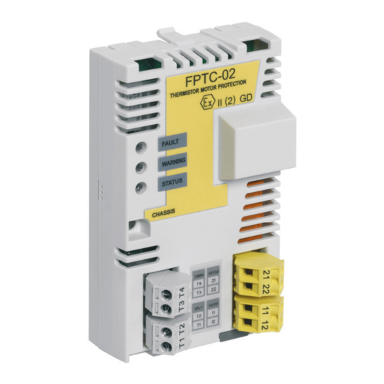
- Page 1 — ABB INDUSTRIAL DRIVES FPTC-02 ATEX-certified thermistor protection module, Ex II (2) GD (option +L537+Q971) for ACS880 drives User's manual...
- Page 3 Ex II (2) GD (option +L537+Q971) for ACS880 drives User's manual Table of contents 1. Safety instructions 5. Mechanical installation 6. Electrical installation 8. Start-up and acceptance test 3AXD50000027782 Rev E © 2020 ABB Oy. All Rights Reserved. EFFECTIVE: 2020-02-28...
-
Page 5: Table Of Contents
Table of contents 5 Table of contents 1 Safety instructions Contents of this chapter ............Use of warnings and notes ............ATEX-certified motor thermal protection functions ....Electrical safety precautions ............. 2 Introduction to the manual Contents of this chapter ............Applicability ................ - Page 6 Commissioning the drive for a motor in a hazardous area ..Resetting the safety function ............ Indications of the safety function ..........Fault reaction function ............... FPTC-02 module ..............STO function in the drive/inverter modules ......FSO module ............... 5 Mechanical installation Contents of this chapter ............
- Page 7 Acceptance test reports ............Acceptance test ................ 9 Fault tracing Contents of this chapter ............Reporting problems and failures related to safety functions ..FPTC-02 module replacement ..........Fault and warning messages ............ LEDs ..................10 Maintenance Contents of this chapter ............
- Page 8 8 Table of contents Connections ................Motor thermistor connection ..........STO output connection ............Ambient conditions ..............Safety data ................Safety block diagrams ............... Two-channel configurations ..........One-channel configurations ..........Response times ................ Relevant failure modes ............. Related standards and directives ..........Compliance with the European Machinery Directive ....
-
Page 9: Safety Instructions
Safety instructions 9 Safety instructions Contents of this chapter This chapter contains the safety instructions which you must obey when you install, operate and do maintenance on the safety functions of a drive. Use of warnings and notes Warnings tell you about conditions which can cause injury or death, or damage to the equipment. -
Page 10: Atex-Certified Motor Thermal Protection Functions
10 Safety instructions WARNING! General warning tells about conditions, other than those caused by electricity, which can cause injury or death, or damage to the equipment. WARNING! Electrostatic sensitive devices warning tells you about the risk of electrostatic discharge which can cause damage to the equipment. - Page 11 Safety instructions 11 • For ACS880 liquid-cooled multidrives, multidrive modules and single drive modules, see ACS880 liquid-cooled multidrive cabinets and modules safety instructions (3AXD50000048633 [English]). WARNING! The functions described in this manual do not disconnect the voltage of the main and auxiliary circuits from the drive. Do not do work on the drive, motor cable or motor when they are energized.
-
Page 12: Electrical Safety Precautions
12 Safety instructions Electrical safety precautions These electrical safety precautions are for all personnel who do work on the drive, motor cable or motor. WARNING! Obey these instructions. If you ignore them, injury or death, or damage to the equipment can occur. If you are not a qualified electrical professional, do not do installation or maintenance work. - Page 13 Safety instructions 13 • If you have a permanent magnet motor connected to the drive, disconnect the motor from the drive with a safety switch or by other means. • Disconnect any dangerous external voltages from the control circuits. • After you disconnect power from the drive, always wait 5 minutes to let the intermediate circuit capacitors discharge before you continue.
- Page 14 14 Safety instructions 6. If the drive is not equipped with a grounding switch, install temporary grounding as required by the local regulations. 7. Ask the person in control of the electrical installation work for a permit to work.
-
Page 15: Introduction To The Manual
Introduction to the manual Contents of this chapter This chapter gives basic information on the manual. Applicability This manual is applicable to the FPTC-02 module and to the Safe motor temperature safety (SMT) function which uses the FPTC-02 module (option +L537+Q971). Compatibility The FPTC-02 module is compatible with: •... -
Page 16: Target Audience
16 Introduction to the manual • ACS880 primary control program version 2.10 or later. For the compatibility of other control programs, contact your local ABB representative. Target audience The manual is intended for people who install, start-up, use and service the ATEX-certified thermistor protection module of the drive. - Page 17 ACS-AP-x assistant control panels user’s manual 3AUA0000085685 FSO-12 safety functions module user's manual 3AXD50000015612 FSO-21 safety functions module user’s manual 3AXD50000015614 FSE-31 pulse encoder interface module user’s manual 3AXD50000016597 FPTC-02 ATEX-certified thermistor protection module, 3AXD50000027782 Ex II (2) GD (option +L537 +Q971) user’s manual...
-
Page 18: Terms And Abbreviations
Types of protection, increased safety (EN/IEC 60079-7) Ex motors Motors used in explosive atmospheres FEA-03 Optional I/O extension adapter FPTC-02 Optional ATEX-certified thermistor protection module for po- tentially explosive atmospheres FSE-31 Optional pulse encoder interface module for safety encoder FSO-21... - Page 19 Introduction to the manual 19 Term Description MTTF Mean time to dangerous failure: (Total number of life units) / (Number of dangerous, undetected failures) during a partic- ular measurement interval under stated conditions (EN ISO 13849-1) Average probability of dangerous failure on demand (IEC 61508) Average frequency of dangerous failures per hour (IEC 61508)
- Page 20 20 Introduction to the manual Term Description Mission time: the period of time covering the intended use of the safety function/device. After the mission time elapses, the safety device must be replaced. Note that any T values given cannot be regarded as a guarantee or warranty. (EN ISO 13849-1) Zone Potentially explosive atmosphere.
-
Page 21: Hardware Description
The FPTC-02 module implements the Safe motor temperature (SMT) safety function as defined in EN/IEC 61800-5-2. The FPTC-02 module is Type Examined as a protective device within the scope of the European ATEX Product Directive. This allows the use of the module in temperature protection of motors in explosive atmospheres (Ex motors). -
Page 22: Operation Basics
22 Hardware description board is PELV compatible also when the FPTC-02 module and a thermistor protection circuit are installed. ■ Operation basics The module includes two PTC sensor inputs: • XFLT activates the ATEX-certified SIL/PL capable SMT safety function by activating the drive Safe torque off (STO) function. -
Page 23: Layout
Hardware description 23 ■ Layout XSTO2 XWRN XSTO1 XFLT Retaining clips Lock... -
Page 24: Markings
Y: Last digit of the manufacturing year (for example, 5 = 2015) WW: Manufacturing week (for example, 01 = week 1) SSSS: Number that starts every week from 0001 WS: Manufacturing location ABB MRP code of the module Combined ABB MRP code, serial number and manufacturing location RoHS mark... -
Page 25: Atex Markings
■ Drive Option +Q971 When the FPTC-02 module is ordered as a factory-installed option, an additional sticker is sometimes attached to the drive/module to signify ATEX classification of the drive Safe disconnection function (+Q971) of the drive/module. This sticker and the ATEX certification... -
Page 26: Smt Function
Safe disconnection function. SMT function When the FPTC-02 module is delivered as an add-on kit, the package contains a sticker to show the ATEX classification of the Safe motor temperature (SMT) function. The user must attach this sticker to the... - Page 27 Hardware description 27 In the factory-installed options, this sticker is already attached to the drive/inverter module at the factory. In the cabinet-built drives, this sticker is attached to the cabinet door at the factory. CE marking with Notified Body identification: The manufacturer declares that the product conforms with ATEX Product Directive 2014/34/EU.
-
Page 29: Option Description And Instructions
Contents of this chapter This chapter describes the Safe motor temperature function implemented with the FPTC-02 module and the drive Safe torque off function and gives instructions for the user. Overview To implement the Safe motor temperature (SMT) function, you can connect the FPTC-02 module directly to the drive Safe torque off (STO) circuit, or you can use it together with an FSO module. -
Page 30: Drives And Modules
30 Option description and instructions Note: The Safe motor temperature function is motor-specific. This is the case also in ACS880 multidrives where multiple motors are connected to the drive. ■ Drives and modules The module is available as a factory-installed option (+L537+Q971) or as an add-on kit for ACS880 drives and modules. -
Page 31: The Atex-Certified Safe Disconnection Function
Product Directive 2014/34/EU. For more information on the drive STO function, see the applicable hardware manual. You can use the FPTC-02 module only when serial number of the drive/inverter module starts with 1, 4, 7, 8, M or Y. Note: You do not need a separate ATEX certification (and label) for... -
Page 32: Indications Of The Safety Function
32 Option description and instructions When the XWRN input detects a motor overtemperature situation, the FPTC-02 module generates a warning to the drive. This is not a safety-related function and does not need a reset. If an FSO module is used together with the FPTC-02 module, it is possible that the user must reset the safety function also with a reset button connected to the FSO module. -
Page 33: Fault Reaction Function
Fault reaction function ■ FPTC-02 module The FPTC-02 module has a fault reaction function. When the module detects an internal fault or a fault in the temperature sensor circuit, it sends a request to the drive control unit to stop modulation, and activates the drive STO function. - Page 34 34 Option description and instructions Fail-safe mode, remove the cause of the fault and reset the FSO module. To reset the FSO module: • switch the power off and on, or • press the Boot FSO button on the Safety view of Drive composer pro, or •...
-
Page 35: Mechanical Installation
For a complete list of tools, see the applicable drive hardware manual. Unpacking and examining the delivery 1. Open the option package. 2. Make sure that the package contains: • FPTC-02 module • STO cable • ATEX label (with the ATEX classification markings) •... -
Page 36: Installing The Module
See the applicable drive manual for further instructions on how to install the module to the drive. Do not install the FPTC-02 module on an FEA-03 F-series extension adapter. The diagnostics of the module requires that you install it directly on the drive control unit. - Page 37 Mechanical installation 37...
-
Page 39: Electrical Installation
Electrical installation 39 Electrical installation Contents of this chapter This chapter contains instructions on wiring the module. Warnings WARNING! Obey the safety instructions of the drive. If you ignore them, injury or death, or damage to the equipment can occur. If you are not a qualified electrical professional, do not do installation or maintenance work. -
Page 40: Necessary Tools And Instructions
3. Install the drive or inverter unit, including the components of the ATEX-certified motor thermal protection function, outside the potentially explosive atmosphere. 4. For the sensor connection, ABB recommends to use shielded twisted-pair cable. This type of cable decreases electromagnetic interference in the sensor circuit. -
Page 41: Terminal Designations
XWRN PTC WARNING (non-safety related) In, 0 … +5 V DC Wiring This section shows five methods to connect the FPTC-02 module to the drive STO terminals. Wiring example 1 (page 43): The STO outputs of the FPTC-02 module are connected directly to the STO terminals of the drive. - Page 42 Wiring example 3 (page 45): An external safety relay is connected between the FPTC-02 module and the drive STO inputs with a two-channel connection. Wiring example 4 (page 46): The STO outputs of the FPTC-02 module are connected directly to the STO terminals of the drive with a one-channel connection.
-
Page 43: Wiring Example 1
Electrical installation 43 ■ Wiring example 1 This connection is SIL2 capable (redundancy between STO channels). FPTC XSTO XSTO1 SGND XSTO2 XFLT SLOT X100 1/2/3 Ex M Control unit Potentially explosive atmosphere a) If necessary, you can connect an external device (for example, an emergency stop button) between the XSTO input of the control unit and the XSTO1 and XSTO2 outputs of the FPTC module. -
Page 44: Wiring Example 2
44 Electrical installation ■ Wiring example 2 With an FSO module, two-channel connection. This connection is SIL2 capable (redundancy between STO channels). FPTC XSTO XSTO1 SGND XSTO2 XFLT SLOT X100 1/2/3 X111 Ex M X113 X114 Control unit Potentially explosive atmosphere... -
Page 45: Wiring Example 3
Electrical installation 45 ■ Wiring example 3 With an external safety relay, two-channel connection. This connection is SIL2 capable (redundancy between STO channels). FPTC XSTO XSTO1 SGND XSTO2 XFLT SLOT X100 1/2/3 Ex M Control unit External safety relay Potentially explosive atmosphere... -
Page 46: Wiring Example 4
46 Electrical installation ■ Wiring example 4 One-channel connection. This connection is SIL1 capable (no redundancy between STO channels). FPTC XSTO XSTO1 SGND XSTO2 XFLT SLOT X100 1/2/3 Ex M Control unit Potentially explosive atmosphere a) If necessary, you can connect an external device (eg, an emergency stop button) between the XSTO input of the control unit and the XSTO2 output of the FPTC module. -
Page 47: Wiring Example 5
Electrical installation 47 ■ Wiring example 5 With an FSO module, one-channel connection. This connection is SIL1 capable (no redundancy between STO channels). FPTC XSTO XSTO1 SGND XSTO2 XFLT SLOT X100 1/2/3 X111 Ex M X113 X114 Control unit Potentially explosive atmosphere... -
Page 49: Parameter Settings
Parameter settings 49 Parameter settings Contents of this chapter This chapter contains the drive and FSO module parameter settings. Drive / inverter Use the Drive composer PC tool or the control panel to set the parameter values. This table lists the parameters related to the safety function in ACS880 primary control program. - Page 50 This parameter value does not have an ef- fect on the SMT function, but this is the re- commended setting. For the cabinet-built drives, ABB has set this value at the fact- ory.
- Page 51 Parameter settings 51 Index Name Description 35.30 FPTC configuration Activates FPTC modules installed on the word control unit of the drive. With this word, it is also possible to sup- press the non-safety related motor temper- ature warnings (XWRN input). It is not possible to suppress the SMT faults (XFLT input).
-
Page 52: Switching Frequency Limitation
EX motor 1 = The driven motor is an Ex motor provided by ABB for potentially explosive atmospheres. This sets the required minim- um switching frequency for ABB Ex motors. For non-ABB Ex motors, contact your local ABB representative. ■... -
Page 53: Other Recommended Settings
Parameter settings 53 For ABB Ex motors, use parameter 95.15 to set the required minimum switching frequency. For more information, see the drive firmware manual. For Ex motors supplied by other motor manufacturers, contact the motor manufacturer for the correct value and your local ABB representative for instructions on how to make the parameter setting in the drive. - Page 54 54 Parameter settings There are parameters that you must always set when you use the FSO module, and parameters that are related only to some safety functions. This chapter lists the parameters that are relevant to the option +L537+Q971+Q973 (with FSO-12) and +L537+Q971+Q972 (with FSO-21).
-
Page 55: General Parameters
Parameter settings 55 ■ General parameters These parameters are common to all safety functions in the FSO module. Index Name Example Description value FSO- Stop completed Sets the digital output that indicates the None GEN.11 output completion of any stop function. Active when the FSO module has completed the STO, SSE or SS1 function. -
Page 56: Parameters For The Sto Function
56 Parameter settings Index Name Example Description value FSO- STO indication Sets the type of the event that the FSO Warning GEN.61 ext request module generates and sends to the drive after external requests that end to a successful activation of the drive STO function (STO, SSE or SS1). - Page 57 Parameter settings 57 Index Name Example Description value STO.12 STO input B DI X113:4 Sets the digital input that is connected & X114:4 to the secondary input of the STO function. Note: In a non-redundant system, you can use a one-channel input (for ex- ample, DI X113:4).
- Page 58 58 Parameter settings Index Name Example Description value STO.14 Time to zero 2000 ms Sets the time that is needed to coast speed with the motor to a standstill from maximum STO and mod- process speed. If this time is not known, it can be measured with Drive composer pro PC tool when an encoder is used for motor control (otherwise you...
-
Page 59: Parameters For The Sse Function
Parameter settings 59 Index Name Example Description value I/O settings SAFEIO.36 DI X113:4 diag Sets the diagnostic pulse of digital input On 1) pulse on/off X113:4 on or off. On: The input monitors that it receives test pulses. SAFEIO.40 DI X114:4 diag Sets the diagnostic pulse of digital input pulse on/off X114:4 on or off. -
Page 60: Fse Module And Safety Pulse Encoder Parameters
60 Parameter settings Index Name Example Description value SBC usage SBC.15 SSE/SS1 SBC 0.0 rpm Sets the absolute speed below which speed the FSO module activates the brake (SBC) while ramping. 0.0 rpm: The feature is not in use. In the safety functions described in this manual, this feature is not used. - Page 61 Parameter settings 61 Index Name Example Description value S_ENC- Enc speed 1.0 rpm Sets the encoder speed cross compar- GEN.14 cross comp tol- ison tolerance. This defines how much erance the axle speed of the motor can change within 1 ms. Adjust the default value to meet the motor in use.
-
Page 62: Notes
62 Parameter settings Index Name Example Description value 92.10 Pulses/revolu- 2048 Sets the number of HTL pulses per re- tion volution for safety pulse encoder 1. Adjust the default value to meet the safety pulse encoder in use. Make sure that the value is according to the en- coder nameplate. - Page 63 Parameter settings 63 If the motor deceleration by the mechanical brake causes extra heat generation in the Ex zone, make sure that the use of the brake does not increase the temperature too much. In some cases you cannot use the brake for the motor deceleration when the motor thermal protection circuit has tripped and the motor temperature is too high.
-
Page 65: Start-Up And Acceptance Test
Start-up and acceptance test 65 Start-up and acceptance test Contents of this chapter This chapter describes the start-up, acceptance test procedure, and validation of the safety function. Validation of the safety functions You must do an acceptance test (validation) to validate the correct operation of safety functions. -
Page 66: Validation Procedure
66 Start-up and acceptance test ■ Validation procedure You must do the acceptance test using the checklist given in section Start-up and acceptance test: • at initial start-up of the safety function • after any changes related to the safety function (wiring, components, safety-function-related parameter settings, etc.) •... -
Page 67: Acceptance Test
Start-up and acceptance test 67 Acceptance test Use the Drive composer PC tool or the control panel to do the acceptance test. Action Initial status Make sure that the drive is ready for use, that is, you have done the tasks of the drive start-up procedure. - Page 68 68 Start-up and acceptance test Action Settings with voltage connected Make sure that you have activated the FPTC module in the correct slot (parameter 35.30). Make sure that you have set all the necessary parameters for the safety function. See chapter Parameter settings.
- Page 69 Start-up and acceptance test 69 Action Restart the drive and the motor. Make sure that they operate normally. If in use, test the XWRN input: Connect a resistor (resistance 100 ohm … 1 kohm) between the XWRN inputs. Make sure that the motor temperature warning indication is activated in motor overtemper- ature and short-circuit situations.
-
Page 71: Fault Tracing
LEDs on the module. Reporting problems and failures related to safety functions Contact ABB. FPTC-02 module replacement If there is a failure in the FPTC-02 module, you have to replace it with a new one. You cannot repair the module. -
Page 72: Fault And Warning Messages
35.30 but cannot be detected. in the option slot. The last digit of the auxiliary code identifies the slot. 4991 The FPTC-02 module in Safe motor Make sure that the option slot 1 indicates temperature motor has sufficient overtemperature in the 1 1) cooling. - Page 73 Fault tracing 73 Code Name Cause Action (hex) Warnings A497 The FPTC module in Motor Make sure that the option slot 1 has activated temperature motor has sufficient a motor temperature cooling. warning in the XWRN input Make sure that the (non-safety related).
-
Page 74: Leds
74 Fault tracing LEDs The FPTC-02 module has three diagnostic LEDs. Name Color Description FAULT The motor temperature is outside the permitted temperature range and the drive STO is active, or there is no PTC sensor connected to the XFLT input (safety-related). -
Page 75: Maintenance
If you change any wiring or component after the start-up, replace the FPTC-02 module, modify parameters, or restore parameters to their factory default values: • Use only ABB-approved spare parts. -
Page 76: Proof Test Interval
This is a recommendation and depends on the required (not achieved) SIL/PL. For example, contactors, breakers, safety relays, contactor relays, emergency stop buttons, switches etc. are typically safety devices which contain electromechanical outputs. The FPTC-02 and FSO modules and the STO circuit of the drive do not contain electromechanical outputs. -
Page 77: Competence
Maintenance 77 Competence The maintenance and proof test activities of the safety function must be carried out by a competent person with expertise and knowledge of the safety function as well as functional safety, as required by IEC 61508-1 clause 6 and ATEX/Ex regulations. Residual risk The safety functions are used to reduce the recognized hazardous conditions. -
Page 79: Technical Data
Technical data 79 Technical data Contents of this chapter This chapter contains the technical data of the module, gives general rules, notes and definitions related to safety functions and lists the related standards and directives. The safety data, relevant certificates and Declarations of Conformity are also included. -
Page 80: Dimension Drawing
80 Technical data Dimension drawing The dimensions are shown in millimeters and inches. Isolation areas The following figure shows the different isolation areas of the module. Isolation areas A and B and the mounting screw are connected to ground. Isolation area C is in the same potential as the PTC sensor element in the motor. -
Page 81: Connections
Technical data 81 XSTO1 XSTO2 XWRN XFLT Connection to the drive Mounting screw, chassis PTC Warning PTC Fault STO 1 STO 2 There is reinforced insulation between: • isolation areas A and C • isolation areas B and C. Connections ■... -
Page 82: Sto Output Connection
Safety data The FPTC-02 module is a type A safety component as defined in IEC 61508-2. For the types of the drive/inverter STO and the FSO module, see the applicable hardware manual or FSO user's manual. - Page 83 4.88E-05 4.81E-05 6.17E-05 6.71E-05 = 2 a 1.20E-04 1.21E-04 1.20E-04 1.56E-04 1.69E-04 = 5 a DC (%) Cat. 3AXD10000454332 E The MTTF value (EN ISO 13849-1) of the FPTC-02 module: • 1708 years (two-channel connection) • 1703 years (one-channel connection)
-
Page 84: Safety Block Diagrams
84 Technical data Safety block diagrams The components that are included in the safety data calculations are shown in the safety block diagrams below. Note: The failure rate of the PTC sensor is not included in the calculations. ■ Two-channel configurations This diagram is applicable to configuration 1. -
Page 85: One-Channel Configurations
Technical data 85 This diagram is applicable to configuration 3. PTC sensor FPTC module External safety relay Drive STO Note: The failure rate of the external safety relay is not included in the calculation. ■ One-channel configurations This diagram is applicable to configuration 4. PTC sensor FPTC module Drive STO... -
Page 86: Response Times
Response times • FPTC-02 module: less than 10 ms • SMT function: the response time of the PTC sensor + FPTC-02 module (< 10 ms) + FSO module (< 50 ms) + drive STO (< 50 ms) Relevant failure modes •... -
Page 87: Related Standards And Directives
Technical data 87 Related standards and directives EN 50495:2010 Safety devices required for the safe functioning of equip- ment with respect to explosion risks IEC 61508:2010 Functional safety of electrical/electronic/programmable electronic safety-related systems. Part 1 – General Requirements Part 2 – Requirements for electrical/electronic/program- mable electronic safety-related systems EN 61800-5- Adjustable speed electrical power drive systems –... -
Page 88: Compliance With The European Machinery Directive
88 Technical data Compliance with the European Machinery Directive The drive is an electronic product which is covered by the European Low Voltage Directive. However, the drive internal safety function of this manual (option +L537+Q971) is in the scope of the Machinery Directive as a safety component. - Page 89 Technical data 89...
- Page 90 90 Technical data...
-
Page 91: Atex Certificate
Technical data 91 ATEX certificate ATEX certificate for the Safe motor temperature function with the FPTC-02 module and ACS880 drive series (VTT 15 ATEX 050). - Page 92 92 Technical data...
- Page 93 Technical data 93 Check the latest version of the certificate in the ABB Library.
-
Page 94: Tüv Nord Certificate
94 Technical data TÜV Nord certificate TÜV Nord certificate for the FPTC-02 module and ACS880 drive series is attached below. - Page 95 Address any inquiries about the product to your local ABB representative, quoting the type designation and serial number of the unit in question. A listing of ABB sales, support and service contacts can be found by navigating to www.abb.com/searchchannels. Product training For information on ABB product training, navigate to new.abb.com/service/training.
- Page 96 3AXD50000027782E © 2020 ABB Oy. All Rights Reserved. Specifications subject to change without notice.