ABB FECA-01 User Manual
Ethercat adapter module
Hide thumbs
Also See for FECA-01:
- Quick installation and start-up manual (2 pages) ,
- Quick installation and start-up manual (2 pages)

Related Manuals for ABB FECA-01


Summary of Contents for ABB FECA-01
- Page 1 Options for ABB drives, converters and inverters User’s manual FECA-01 EtherCAT® adapter module...
- Page 2 List of related manuals See section Related manuals on page 16. EtherCAT® is registered trademark and patented technology, licensed by Beckhoff Automation GmbH, Germany.
- Page 3 User’s manual FECA-01 EtherCAT® adapter module Table of contents 1. Safety instructions 4. Mechanical installation 5. Electrical installation 6. Start-up 3AUA0000068940 Rev D 2015 ABB Oy All Rights Reserved. EFFECTIVE: 2015-06-15...
-
Page 5: Table Of Contents
Example topology of the EtherCAT link ....22 FECA-01 EtherCAT adapter module ..... 23 Layout of the adapter module . - Page 6 EtherCAT Slave Information files ..... 55 Configuring an ABB AC500 PLC ..... 55 Configuring Beckhoff’s TwinCAT .
- Page 7 Control word and Status word of the CiA 402 profile ..73 ABB Drives communication profile ..... . . 78 Control word and Status word .
- Page 8 FECA-01 ........
- Page 9 Product training ........147 Providing feedback on ABB Drives manuals ....147...
-
Page 10: Table Of Contents
10 Table of contents... -
Page 11: Safety Instructions
Safety instructions 11 Safety instructions Contents of this chapter The chapter contains the warning symbols used in this manual and the safety instructions which you must obey when you install or connect an optional module to a drive, converter or inverter. If you ignore the safety instructions, injury, death or damage can occur. -
Page 12: Use Of Warnings
12 Safety instructions Use of warnings Warnings tell you about conditions which can cause injury or death, or damage to the equipment. They also tell you how to prevent the danger. The manual uses these warning symbols: Electricity warning tells you about hazards from electricity which can cause injury or death, or damage to the equipment. -
Page 13: Safety In Installation And Maintenance
Safety instructions 13 Safety in installation and maintenance These instructions are for all who install or connect an optional module to a drive, converter or inverter and need to open its front cover or door to do the work. WARNING! Obey these instructions. If you ignore them, injury or death, or damage to the equipment can occur. - Page 14 14 Safety instructions...
-
Page 15: About This Manual
This chapter introduces this manual. Applicability ® This manual applies to the FECA-01 EtherCAT adapter module (+K469), SW version 112. Compatibility The FECA-01 EtherCAT adapter module is compatible with the following drives: • ACS355 • ACSM1 (motion and speed variants) •... -
Page 16: Target Audience
Purpose of the manual The manual provides information on installing, commissioning and using an FECA-01 EtherCAT adapter module. Related manuals The related manuals are listed below. Code (English) Drive user’s manuals... -
Page 17: Before You Start
Document library on the Internet the inside of the back cover. For manuals not available in the Document library, contact your local ABB representative. Before you start It is assumed that the drive is installed and ready to operate before you start the installation of the adapter module. -
Page 18: Contents
• About this manual introduces this manual. • Overview of the EtherCAT network and the FECA-01 module contains a short description of the EtherCAT network and the adapter module. • Mechanical installation contains a delivery checklist and instructions on mounting the adapter module. -
Page 19: Terms And Abbreviations Used In This Manual
(sometimes called the Command word) FECA-01 EtherCAT One of the optional fieldbus adapter modules adapter module available for ABB drives. FECA-01 is a device through which an ABB drive is connected to an EtherCAT network. Parameter Operating instruction for the drive. Parameters... -
Page 20: Ethercat Abbreviations
20 About this manual Abbreviation Explanation Foil shielded twisted pair Internet Protocol Least significant bit Most significant bit Shielded twisted pair User Datagram Protocol Unshielded twisted pair Extensible Markup Language EtherCAT abbreviations Abbreviation Explanation CANopen over EtherCAT EMCY Emergency Object Ethernet over EtherCAT EtherCAT Slave Controller EtherCAT Slave Information... -
Page 21: Overview Of The Ethercat Network And The Feca-01
Overview of the EtherCAT network and the FECA-01 module 21 Overview of the EtherCAT network and the FECA-01 module What this chapter contains This chapter contains a short description of the EtherCAT network and the FECA-01 EtherCAT adapter module. EtherCAT network EtherCAT is a Real Time Ethernet technology which aims to maximize the use of the full duplex Ethernet bandwidth. -
Page 22: Example Topology Of The Ethercat Link
22 Overview of the EtherCAT network and the FECA-01 module Further information is available from the EtherCAT technology group (www.ethercat.org). Example topology of the EtherCAT link An example of an allowable topology is shown below. adapter adapter adapter module... -
Page 23: Feca-01 Ethercat Adapter Module
Overview of the EtherCAT network and the FECA-01 module 23 FECA-01 EtherCAT adapter module The FECA-01 EtherCAT adapter module is an optional device for ABB drives which enables the connection of the drive to an EtherCAT network. Through the adapter module you can: •... -
Page 24: Layout Of The Adapter Module
24 Overview of the EtherCAT network and the FECA-01 module Layout of the adapter module Lock Mounting screw Front view Diagnostic LEDs (see chapter Diagnostics) EtherCAT EtherCAT connector X1 connector X2 Side view... -
Page 25: Mechanical Installation
See the applicable drive hardware manual. Unpacking and examining the delivery 1. Open the option package. 2. Make sure that the package contains: • EtherCAT adapter module, type FECA-01 • this manual. 3. Make sure that there are no signs of damage. -
Page 26: Installing The Adapter Module
26 Mechanical installation Installing the adapter module WARNING! Obey the safety instructions. See chapter Safety instructions on page 11. If you ignore the safety instructions, injury or death can occur. The adapter module has a specific position in the drive. Plastic pins, a lock and one screw to hold the adapter module in place. - Page 27 Mechanical installation 27 3. Push in the lock. 4. Tighten the screw to torque 0.8 N·m. Note: It is necessary to tighten the screw properly to fulfill the EMC requirements and to ensure the proper operation of the module. See the applicable drive manual for further instructions on how to install the adapter module to the drive.
- Page 28 28 Mechanical installation...
-
Page 29: Electrical Installation
Electrical installation 29 Electrical installation Contents of this chapter This chapter contains: • general cabling instructions • instructions on connecting the adapter module to the EtherCAT network. Warnings WARNING! Obey the safety instructions. See chapter Safety instructions on page 11. If you ignore the safety instructions, injury or death can occur. -
Page 30: General Cabling Instructions
30 Electrical installation General cabling instructions • Arrange the bus cables as far away from the motor cables as possible. • Avoid parallel runs. • Use bushings at cable entries. When you connect the network cables, insert the plug into the jack so that there is no misalignment. - Page 31 Electrical installation 31 The figure below illustrates the cable connections: adapter adapter adapter module module module EtherCAT master...
- Page 32 32 Electrical installation...
-
Page 33: Start-Up
Start-up 33 Start-up What this chapter contains This chapter contains: • information on configuring the drive for operation with the adapter module • drive-specific instructions on starting up the drive with the adapter module • examples of configuring the master station for communication with the adapter module. -
Page 34: Drive Configuration
34 Start-up Drive configuration The following information applies to all drive types compatible with the adapter module, unless otherwise stated. EtherCAT connection configuration After the adapter module has been mechanically and electrically installed according to the instructions in chapters Mechanical installation Electrical... -
Page 35: Feca-01 Configuration Parameters - Group A (Group 1)
Start-up 35 FECA-01 configuration parameters – group A (group 1) Note: The actual parameter group number depends on the drive type. Group A (group 1) corresponds to: • parameter group 51 in ACS355, ACSM1, ACS580 and ACS850. • parameter group is typically 51/54 (group 151/154 in some variants) in ACS880 if the adapter is installed as fieldbus adapter A/B. - Page 36 36 Start-up Name/Value Description Default STATION ALIAS Configured Station Alias address used for node addressing. Use of this alias is activated ACS355: by the master. FB PAR 3 ACSM1: FBA PAR3 ACS850: FBA par3 ACS880/ ACS580: Station alias Reserved These parameters are not used by the …...
- Page 37 Start-up 37 Name/Value Description Default FBA PAR Validates any changed adapter module 0 = Done REFRESH configuration parameter settings. After refreshing, the value reverts automatically to ACS355/ACSM1: 0 = Done. FBA PAR Note: This parameter cannot be changed REFRESH while the drive is running. ACS850/ACS880/ ACS580: FBA par refresh...
- Page 38 38 Start-up Name/Value Description Default MAPPING FILE Read-only. Displays the fieldbus adapter module mapping file revision stored in the memory of the drive in decimal format. ACS355: FILE CONFIG REV ACSM1: MAPPING FILE ACS850/ACS880/ ACS580: Mapping file ver Mapping file revision D2FBA COMM STA Read-only.
- Page 39 Start-up 39 Name/Value Description Default FBA COMM SW Read-only. Displays the common program revision of the adapter module. ACS355: FBA CPI FW REV ACSM1: FBA COMM SW ACS850: FBA comm sw ver ACS880/ACS580: FBA comm SW ver Common program revision of the adapter module FBA APPL SW Read-only.
-
Page 40: Feca-01 Configuration Parameters - Group B (Group 2)
40 Start-up FECA-01 configuration parameters – group B (group 2) Note: The actual parameter group number depends on the drive type. Group B (group 2) corresponds to: • parameter group 55 in ACS355 • parameter group 53 in ACSM1, ACS580 and ACS850 •... -
Page 41: Starting Up Fieldbus Communication For Acs355 Drives
1. Power up the drive. 2. Enable the communication between the adapter module and the drive with parameter 9802 COMM PROT SEL. 3. Set the FECA-01 configuration parameters in parameter group 51. At the minimum, select the communication profile with parameter 5102. -
Page 42: Parameter Setting Examples - Acs355
Displays the type of the fieldbus adapter module. 5102 FB PAR 2 0 (= CiA 402) Selects the CiA 402 profile. (PROFILE) 5127 FBA PAR REFRESH Validates the FECA-01 REFRESH configuration parameter settings. 1001 EXT1 COMM Selects the fieldbus interface as COMMANDS... - Page 43 Start-up 43 Drive parameter Setting for ACS355 Description drives 1608 START ENABLE 1 COMM Selects the fieldbus interface as the source for the inverted Start Enable signal. 1609 START ENABLE 2 COMM Selects the fieldbus interface as the source for the Start Enable 2 signal.
-
Page 44: Starting Up Fieldbus Communication For Acsm1 Drives
50.01 FBA ENABLE to Enable. 3. Select application-specific values for parameters 50.04 and 50.05. The allowed values are shown in the table below. 4. Set the FECA-01 configuration parameters in parameter group 51. At the minimum, set 51.02 PROFILE according to the application. -
Page 45: Parameter Setting Examples - Acsm1
2. 51.02 FBA PAR2 0 (= CiA 402) Selects the CiA 402 profile. (PROFILE) 51.27 FBA PAR REFRESH Validates the FECA-01 REFRESH configuration parameter settings. 10.01 EXT1 START Selects the fieldbus interface as FUNC the source of the start and stop commands for external control location 1. - Page 46 46 Start-up Drive parameter Setting for ACSM1 Description drives 10.08 FAULT RESET P.FBA MAIN CW.8 Selects the fieldbus interface as the source for the fault reset signal. 24.01 SPEED REF1 SEL FBA REF1 Selects the fieldbus reference 1 as the source for speed reference 1.
- Page 47 Start-up 47 Drive parameter Setting for ACSM1 Description drives 62.02 HOMING START Normal Mandatory setting if the homing FUNC procedure will be used 62.03 HOMING START P.2.12 FBA MAIN Mandatory setting if the homing CW.26 procedure will be used 65.01 POS Ref table Mandatory setting REFSOURCE...
-
Page 48: Starting Up Fieldbus Communication For Acs850 Drives
50.01 FBA enable to Enable. 3. Select application-specific values for parameters 50.04 and 50.05. The allowed values are listed in the table below. 4. Set the FECA-01 configuration parameters in drive parameter group 51. At the minimum, set 51.02 PROFILE according to the application. -
Page 49: Parameter Setting Examples - Acs850
51.02 FBA par2 0 (= CiA 402) Selects the CiA 402 profile. (PROFILE) 51.27 FBA par refresh Refresh Validates the FECA-01 configuration parameter settings. 10.01 Ext1 start func Selects the fieldbus interface as the source of the start and stop commands for external control location 1. - Page 50 50 Start-up Drive parameter Setting for ACS850 Description drives 12.01 Ext1/Ext2 sel C.False Selects external control location EXT1. 12.03 Ext1 ctrl mode Speed Selects the default (power up) Torque drive control mode. 21.01 Speed ref1 sel FBA ref1 Selects the fieldbus reference 1 as the source for speed reference 1.
-
Page 51: Starting Up Fieldbus Communication For Acs880 And Acs580 Drives
5. Select application-specific values for parameters 50.04 and 50.05. The allowed values are listed in the table below. 6. Set the FECA-01 configuration parameters in drive parameter group 51. At the minimum, set the value of parameter 51.02 Profile according to the application. - Page 52 52 Start-up 10. CiA 402 profile only: If you intend to use the CiA 402 profile, do the following: • Select the desired operation mode for the adapter module and the drive in CoE object 0x6060 by modifying the object value via the master station.
-
Page 53: Parameter Setting Examples - Acs880 And Acs580
1 = Option slot 1 Enables communication between the drive and the fieldbus adapter module. Select the correct slot where the FECA-01 adapter is installed. 50.02 FBA A comm loss 1 = Fault Enables fieldbus A func communication fault monitoring. - Page 54 54 Start-up Drive parameter Setting for ACS880 Description and ACS580 drives 22.11 Speed ref1 4 = FB A ref1 Selects fieldbus adapter A selection reference value 1 as the source for speed reference 1. 26.11 Torque ref1 4 = FB A ref1 Selects fieldbus adapter A selection reference value 1 as the source...
-
Page 55: Configuring The Master Station
Configuring an ABB AC500 PLC This example shows how to configure communication between an ABB AC500 PLC and the adapter module using the ABB Control Builder Plus software. Before you start, make sure that you have downloaded the ESI XML file from the Document library for your adapter module version and drive type (and drive license type with ACSM1). - Page 56 56 Start-up 3. In the window that opens, click Install and browse for the ESI file downloaded from the Document library. 4. Open or create the PLC project that is used to control the drive. 5. Add the CM579-ECAT EtherCAT master device to the PLC project.
- Page 57 Start-up 57 6. Add the FECA-01 module or the drive to the EtherCAT network. 7. Define the CM579-ECAT master properties. 8. Define the FECA-01 properties.
- Page 58 58 Start-up • On the Process Data tab, select the PDOs transferred between the PLC and drive. • On the EtherCAT I/O Mapping tab, type names for the variables that refer to the drive's signals in the PLC program.
- Page 59 Start-up 59 9. Open the PLC program, compile the project and download it to the PLC. Note: Make sure that the variable names defined for the drive's signals are used in the PLC program. Otherwise the communication will not work.
-
Page 60: Configuring Beckhoff's Twincat
60 Start-up Configuring Beckhoff’s TwinCAT This example shows how to read in an existing network on TwinCAT System Manager. Before you start, make sure that you have downloaded the ESI XML file from the Document library for your adapter module version and drive type (and drive license type with ACSM1). - Page 61 Start-up 61 6. Add the drive(s) to the network configuration by scanning the network. Right-click Device 1 (EtherCAT) and select Scan Boxes….
- Page 62 62 Start-up 7. Select the drive, eg, Drive 1 (FECA-01 and ACSM1 motion), and then select the Process Data tab of the drive. On this tab, you can configure and assign PDOs to Sync Managers. • Rx PDOs are transmitted from the master to the module.
- Page 63 Start-up 63...
- Page 64 64 Start-up 8. Perform the PDO configuration as follows: • In the PDO List box, select a PDO. • In the PDO Content box, edit the object mapping of the selected PDO. • In the Sync Manager and PDO Assignment boxes, assign the selected PDOs to the Sync managers.
- Page 65 Additional Tasks -> Task 1. Then, on the Task tab, select the Auto start check box. 11. Change the TwinCAT configuration state using the buttons shown below. For example, take FECA-01 and the drive into the OPERATIONAL mode.
- Page 66 66 Start-up...
-
Page 67: Communication Profiles
With the FECA-01 module, the master may employ either the CANopen CiA 402 (Device Profile Drives and Motion Control) profile or the ABB Drives profile. Both are converted to the native profile (eg, DCU or FBA) by the adapter module. In addition, a Transparent profile is available. -
Page 68: Canopen Device Profile Cia 402
68 Communication profiles CANopen device profile CiA 402 The CiA 402 profile is a standardized device profile used for digital controlled motion products (for example, drives) and is part of the CANopen specification. Additional information can be obtained at www.can-cia.org. Device control state machine The start and stop of the drive and several mode-specific commands are executed by the device control state machine. -
Page 69: Homing Mode
Communication profiles 69 Operation ACSM1 ACSM1 ACS850 ACS355 ACS880 ACS580 mode motion speed Cyclic synchronou s torque mode Cyclic synchronou s velocity mode Cyclic synchronou s position mode Note: Drive synchronization is supported only with ACSM1 drives. In this section, the scalings of the reference and actual values are described for each operation mode. -
Page 70: Profile Velocity Mode
70 Communication profiles Profile velocity mode In the profile velocity operation mode, the module uses the profile velocity control mode of the drive, instead of the Speed control mode. The profile velocity control mode is available only in an ACSM1 drive equipped with Motion Control Program. -
Page 71: Cyclic Synchronous Velocity Mode
Communication profiles 71 Cyclic synchronous velocity mode With this mode, the trajectory generator is located in the master, not in the drive. The master provides target velocity values cyclically and synchronously to the drive that performs velocity and torque control. The velocity command value is object 0x60FF Target velocity. -
Page 72: Process Data Scaling With The Cia 402 Profile
72 Communication profiles Process data scaling with the CiA 402 profile Torque data Torque data is expressed in 0.1% of nominal torque, eg, value 10 = 1% torque. Velocity data Velocity data is expressed in position increments per second (inc/s). -
Page 73: Control Word And Status Word Of The Cia 402 Profile
Communication profiles 73 Control word and Status word of the CiA 402 profile The functionality of the Control word is described in the following tables. The Control word described in the table below can be found in CoE object 0x6040 Controlword and the Status word in CoE object 0x6041 Statusword (see Appendix A –... - Page 74 74 Communication profiles The CiA 402 state machine is controlled by commands issued via Control word bits 7, 3…0. The commands are listed in the table below: Control word bit Command Fault Enable Quick Enable Switch State reset operation Stop voltage transitions bit 7...
- Page 75 Communication profiles 75 The following table describes the functionality of the Status word of the CiA 402 profile: Name Value Description Ready to switch on Not ready to switch on Ready to switch on Switched on Not switched on Switched on Operation enabled Operation not enabled Operation enabled...
- Page 76 76 Communication profiles The following table describes the operation mode specific bits of the Status word of the CiA 402 profile: Bit Velocity Profile Profile Profile Homing cst, mode position velocity torque mode csv, mode mode mode csp (*) Target Target Target Target...
- Page 77 Communication profiles 77 The following figure describes the state machine of the CiA 402 communication profile. From any state (13) CW: Control word FAULT REACTION START ACTIVE SW: Status word SW: xxxxxxxxx0xx1111 Power-on, State transition Fault reaction (14) self-initialization completed NOT READY FAULT TO SWITCH ON...
-
Page 78: Abb Drives Communication Profile
Status word. The contents of the Control word and the Status word are detailed below. The drive states are presented on page 83. The ABB Drives Control word can be found in CoE object 0x2101 and the ABB Drives Status word in CoE object 0x2104. - Page 79 Communication profiles 79 Name Value Description OFF3_CONTROL Continue operation (OFF3 inactive). Emergency stop, stop within the time defined by the drive parameter. Proceed to OFF3 ACTIVE; proceed to SWITCH-ON INHIBITED. Warning: Ensure that the motor and driven machine can be stopped using this stop mode.
- Page 80 80 Communication profiles Name Value Description RAMP_IN_ZERO Normal operation. Proceed to OPERATION. Note: This is effective only if the fieldbus interface is set as the source for this signal by drive parameters. Force the Ramp Function Generator input to zero. RESET 0=>1 A fault is reset if an active fault...
-
Page 81: Status Word Contents
Communication profiles 81 Status word contents The table below shows the contents of the Status word for the ABB Drives communication profile. The upper case boldface text refers to the states shown in the state machine on page 83. Name... - Page 82 82 Communication profiles Name Value Description ABOVE_LIMIT The actual frequency or speed equals or exceeds supervision limit (set by the drive parameter). This is valid in both directions of rotation. The actual frequency or speed is within the supervision limit. EXT_CTRL_LOC External Control Location EXT2 selected...
-
Page 83: State Machine
Communication profiles 83 State machine The state machine for the ABB Drives communication profile is shown below. SWITCH-ON ABB Drives MAINS OFF INHIBITED (SW Bit6=1) communication Power ON (CW Bit0=0) profile NOT READY TO CW = Control word SWITCH ON... -
Page 84: References
The ABB Drives profile references can be found in CoE objects 0x2102 (ABB Drives REF1) and 0x2103 (ABB Drives REF2). ABB drives can receive control information from multiple sources including analog and digital inputs, the drive control panel and the communication module (for example, FECA-01). -
Page 85: Actual Values
Actual values are 16-bit words containing information on the operation of the drive. The functions to be monitored are selected with a drive parameter. The ABB Drives profile actual values can be found in CoE objects 0x2105 (ABB Drives ACT1) and 0x2106 (ABB Drives ACT2). - Page 86 86 Communication profiles...
-
Page 87: Communication Protocol
Communication protocol 87 Communication protocol What this chapter contains This chapter describes the communication on an EtherCAT network. EtherCAT frame structure In EtherCAT, the data between the master and the slaves is transmitted in Ethernet frames. An EtherCAT Ethernet frame consists of one or several EtherCAT telegrams, each addressing individual devices and/or memory areas. -
Page 88: Ethercat Services
88 Communication protocol The EtherCAT frame structure is pictured in the following figure. Each EtherCAT telegram consists of an EtherCAT header, the data area and a working counter, which is incremented by all EtherCAT nodes that are addressed by the telegram and have exchanged associated data. -
Page 89: Addressing Modes And Fmmus
Communication protocol 89 • Logical read write (LRW) • Auto increment physical read multiple write (ARMW) • Configured address read multiple write (FRMW). Addressing modes and FMMUs There are a number of different addressing modes which can be used by the master to communicate with EtherCAT slaves. As a full slave, the adapter module supports the following addressing modes: •... -
Page 90: Sync Managers
90 Communication protocol Sync managers Sync managers control the access to the application memory. Each channel defines a consistent area of the application memory. The adapter module has four sync manager channels. Their functions are described below. Sync manager channel 0 Sync manager 0 is used for mailbox write transfers (mailbox from master to slave). -
Page 91: Ethercat State Machine
Communication protocol 91 EtherCAT state machine The adapter module includes the EtherCAT state machine mandatory for all EtherCAT devices. The state machine is defined in the following figure. The bootstrap state is not supported. Initialization Pre-operational Safe-operational Operational The adapter module enters the Initialization (INIT) state directly after start-up. -
Page 92: Drive Synchronization
92 Communication protocol Drive synchronization The following synchronization types are supported: • Free run = no synchronization • DC sync = synchronization to a DC Sync0 event. Only ACSM1 drives support drive synchronization. To synchronize the drive, set the ACSM1 parameter 57.09 KERNEL SYNC MODE to FBSync. -
Page 93: Canopen Over Ethercat
Communication protocol 93 CANopen over EtherCAT The application layer communication protocol in EtherCAT is based on the CiA 301 communication profile and is called CANopen over EtherCAT, or CoE. The protocol specifies the Object Dictionary in the adapter module, as well as communication objects for exchanging process data and acyclic messages. - Page 94 Transparent CW 2002 Transparent REF1 2003 Transparent REF2 Default mapping with ACS880 and ACS580: 2101 ABB Drives control word 2102 ABB Drives REF1 2103 ABB Drives REF2 The following table shows the default Tx PDO mapping: Tx PDO Mapping object...
- Page 95 Transparent ACT1 2006 Transparent ACT2 Default mapping with ACS880 and ACS580: 2104 ABB Drives status word 2105 ABB Drives ACT1 2106 ABB Drives ACT2 The adapter module has two Sync Manager Channels for process data: SM 2 for output data (Rx data) and SM 3 for input data (Tx data).
-
Page 96: Emergency Objects
96 Communication protocol Emergency Objects Emergency Objects (EMCYs) are used for sending fault information from the communication module and the drive to the EtherCAT network. They are transmitted whenever a fault occurs in the drive or the adapter module. Only one Emergency Object is transmitted per fault. -
Page 97: Cyclic Low Priority Communication
2004 Transparent SW 2002 Transparent REF1 2005 Transparent ACT1 2003 Transparent REF2 2006 Transparent ACT2 2101 ABB Drives control word 2104 ABB Drives status word 2102 ABB Drives REF1 2105 ABB Drives ACT1 2103 ABB Drives REF2 2106 ABB Drives ACT2... - Page 98 98 Communication protocol The cyclic low priority communication service allows transmission of up to 12 x 16-bit words with ACSM1 and ACS850 drives, and 10 x 16-bit words with ACS355 drives, in each direction. If a 32-bit drive parameter is mapped to a PDO, it reserves two word spaces in the cyclic low priority exchange.
-
Page 99: Diagnostics
Diagnostics 99 Diagnostics What this chapter contains This chapter explains how to trace faults with the status LEDs on the adapter module. LED indications The adapter module is equipped with two green LEDs and one bicolor diagnostic LED. The LEDs are described below. - Page 100 100 Diagnostics Name Color Function No link on port 0 LINK/ACT Green Link OK on port 0, no activity (IN/X1) Green flickering Activity on port 0 LINK/ACT No link on port 1 (OUT/X2) Green Link OK on port 1, no activity Green flickering Activity on port 1 INIT state...
-
Page 101: Technical Data
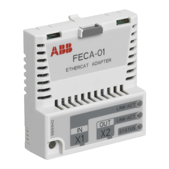
Technical data 101 Technical data What this chapter contains This chapter contains the technical data of the adapter module and the EtherCAT link. FECA-01 The following figure describes the enclosure of the adapter module from the front and side. Supply condition... -
Page 102: Ethercat Link
102 Technical data Mounting Into the option slot on the drive Degree of protection IP20 Ambient conditions The applicable ambient conditions specified for the drive in its manuals are in effect. Indicators Two green LEDs and one bicolor LED: LINK/ACT, LINK/ACT and STATUS Connectors 20-pin connector to the drive (X3) -
Page 103: Appendix A - Coe Object Dictionary
Appendix A – CoE Object Dictionary 103 Appendix A – CoE Object Dictionary What this chapter contains This chapter describes the CANopen over EtherCAT (CoE) Object Dictionary. Object Dictionary structure The objects in the CoE Object Dictionary can be accessed with SDO services, and many of the dictionary objects can be mapped for cyclic communication in PDOs. - Page 104 104 Appendix A – CoE Object Dictionary Explanations for the abbreviations in the columns of the tables are given below: Index Object index (hex) Subindex (hex) Type Data type • U32 = 32-bit unsigned integer (0 … 2 - 1) •...
-
Page 105: Communication Profile Objects (0X1000
• 3: Temperature • 2: Voltage • 1: Current • 0: Generic error (any drive fault). 1008 Device name Constant string is FECA-01 and <drive type>. 1009 Hardware ver- Board revision, eg, A sion 100A Software ver- Firmware name and... - Page 106 106 Appendix A – CoE Object Dictionary Index SI Name Type Information cess 1010 Store parame- Write value ters 0x65766173 into a rel- evant subindex to save NVS object values. Save all param- Save the communica- eters tion and device profile areas.
- Page 107 Index SI Name Type Information cess 1018 Identity Number of entries (4) Vendor ID Value 0xB7 = ABB Drives Product code Product code read from the drive. Eg, val- ue 0x1F7 = ACS355, 0x20A = ACSM1 speed, 0x20B = ACSM1 motion, 0x21C = ACS850, 0x259 = ACS880.
- Page 108 108 Appendix A – CoE Object Dictionary Index SI Name Type Information cess 1601 RxPDO 2 map Number of mapped ob- jects (0...8). Write access in the PREOP state only. Rx PDO 2 mapping en- try 1. Value 0x60400010 = object 6040 Control- word, length 16 bits.
- Page 109 Appendix A – CoE Object Dictionary 109 Index SI Name Type Information cess 1603 RxPDO 4 map Number of mapped ob- jects (0...8). Write access in the PREOP state only. Rx PDO 4 mapping en- try 1. Value 0x60400010 = object 6040 Control- word, length 16 bits.
- Page 110 Rx PDO 21 mapping entry 1. Value 0x20010020 = object 2001 Transpar- ent CW, length 32 bits. ACS880 and ACS580: Value 0x21010010 = object 2101 ABB Drives cw, length 16 bits Rx PDO 21 mapping entry 2. Value 0x20020020 = object 2002 Transpar- ent REF1, length 32 bits.
- Page 111 Appendix A – CoE Object Dictionary 111 Index SI Name Type Information cess 1614 Rx PDO 21 mapping entry 15. Value 0 = none. 1A00 TxPDO 1 map Number of mapped ob- jects (0...8). Write access in the PREOP state only. Tx PDO mapping en- try 1.
- Page 112 112 Appendix A – CoE Object Dictionary Index SI Name Type Information cess 1A02 TxPDO 3 map Number of mapped ob- jects (0…8). Write access in the PREOP state only. Tx PDO 3 mapping en- try 1. Value 0x60410010 = object 6041 Sta- tusword, length 16 bits Tx PDO 3 mapping en-...
- Page 113 Appendix A – CoE Object Dictionary 113 Index SI Name Type Information cess 1A03 TxPDO 4 map Number of mapped ob- jects (0…8). Write access in the PREOP state only. Tx PDO 4 mapping en- try 1. Value 0x60410010 = object 6041 Sta- tusword, length 16 bits Tx PDO 4 mapping en-...
- Page 114 114 Appendix A – CoE Object Dictionary Index SI Name Type Information cess 1A05 TxPDO 6 map Number of mapped ob- jects (0…8). Write access in the PREOP state only. Tx PDO 6 mapping en- try 1. Value 0x60410010 = object 6041 Sta- tusword, length 16 bits.
- Page 115 TxPDO 21 mapping entry 1. Value 0x20040020 = object 2004 Transpar- ent SW, length 32 bits. ACS880 and ACS580: Value 0x21040010 = object 2104 ABB Drives sw, length 16 bits TxPDO 21 mapping entry 2. Value 0x20050020 = object 2005 Transpar- ent ACT1, length 32 bits.
- Page 116 116 Appendix A – CoE Object Dictionary Index SI Name Type Information cess 1A14 TxPDO 21 mapping entry 15. Value 0 = none. 1C00 Sync manager SM0…SM3 communi- communication cation types. type Number of entries (4). Value 1 = mailbox re- ceive (output) Value 2 = mailbox send (input)
- Page 117 Appendix A – CoE Object Dictionary 117 Index SI Name Type Information cess 1C13 Sync manager 3 Number of assigned (Tx) PDO as- PDOs (0…6). sign Write access in the PREOP state only. Sync manager 3 PDO assignment 1. Eg, val- ue 0x1A05 = Tx PDO Sync manager 3 PDO assignment 2.
- Page 118 118 Appendix A – CoE Object Dictionary Index SI Name Type Information cess 1C32 Output sync Sync manager 2 syn- manager pa- chronization settings rameter Synchroniza- 0x00 = Free run (de- tion type fault) 0x01 = SM sync, SM2 event 0x02 = DC Sync0 Synchroniza- Drive dependent.
- Page 119 Appendix A – CoE Object Dictionary 119 Index SI Name Type Information cess 1C33 Input sync man- Sync manager 3 syn- ager parameter chronization settings Synchroniza- 0x00 = Free run (de- tion type fault) 0x01 = SM sync, SM3 event 0x22 = SM sync, SM2 event 0x02 = DC Sync0...
-
Page 120: Manufacturer-Specific Profile Objects (0X2000
120 Appendix A – CoE Object Dictionary Manufacturer-specific profile objects (0x2000...0x5FFF) The manufacturer-specific profile objects contain the ABB Drives profile control and status words, reference value, actual value and diagnostic data. The objects are described in the following table. Index SI... - Page 121 Appendix A – CoE Object Dictionary 121 Index SI Name Type Information cess 2201 Last drive Last fieldbus fault fault code code read from the drive...
- Page 122 122 Appendix A – CoE Object Dictionary Index SI Name Type Information cess 2202 Diagnostic Status/error code number from the adapter module. Indications 1,5,8 are reset by the fault reset mechanism of the currently selected communication profile. All indications are reset by writing the current error number to this object.
-
Page 123: Drive Parameter Access Via Coe Objects
… … … … … Note: The Transparent and ABB Drives command values cannot be changed with an SDO write service. Drive parameter access via CoE objects Drive parameters can be accessed via objects 0x4001…0x4063. The 8 least significant bits of the object index correspond to the drive parameter group and the sub-index is the drive parameter index. -
Page 124: Standardized Device Profile Area (0X6000
124 Appendix A – CoE Object Dictionary Notes: • Drive parameters are not restored to default values with object 0x1011. • Drive parameters, when mapped into a PDO, are transmitted via the cyclic low priority communication service. Standardized device profile area (0x6000…0x9FFF) Index SI Name... - Page 125 Appendix A – CoE Object Dictionary 125 Index SI Name Type Information cess 603F Error code CiA 402 error code of the last error which occurred in the drive. Values according to IEC 61800-7-201. Manufacturer-specific error codes 0xFF00...0xFFFF: In general, all drive fault codes from 0xFF00 and above pass straight through into...
- Page 126 126 Appendix A – CoE Object Dictionary Index SI Name Type Information cess 6044 vl velocity Operational when ve- actual value locity feedback is available from the drive. Note: When ACS355 is used in the scalar control mode, this ob- ject does not indicate axis velocity, but the output frequency of...
- Page 127 Appendix A – CoE Object Dictionary 127 Index SI Name Type Information cess 604A vl velocity Quick stop ramp set- quick stop tings for the vl opera- tion mode Delta speed Ramp delta speed (vl scaling units). Note: Read only in ACS355, ACS580 and ACS880.
- Page 128 128 Appendix A – CoE Object Dictionary Index SI Name Type Information cess 6060 Modes of Rx CiA 402 operation operation mode request. 0 = No mode change (default) 1 = Profile position mode (pp) 2 = Velocity mode (vl) 3 = Profile velocity mode (pv) 4 = Profile torque...
- Page 129 Appendix A – CoE Object Dictionary 129 Index SI Name Type Information cess 6066 Following Time-out (ms) after error time which the status word following an error bit is asserted when the fol- lowing error window is exceeded. Default: 0 (= immedi- ate) 606B Velocity de-...
- Page 130 130 Appendix A – CoE Object Dictionary Index SI Name Type Information cess 607B Position Modulo values for the range limit position command val- ue. When the limits are exceeded, the command value wraps around to the other end of the range. Modulo calculation is disabled when both limit values are zeros.
- Page 131 Appendix A – CoE Object Dictionary 131 Index SI Name Type Information cess 6083 Profile ac- Acceleration during a celeration profiled move. Unit: position incre- ments / s 6084 Profile de- Deceleration during a celeration profiled move. Unit: position incre- ments / s 6085 Quick stop...
- Page 132 132 Appendix A – CoE Object Dictionary Index SI Name Type Information cess Homing See the ACSM1 firm- method ware manual for a de- scription of the homing methods. 0 = No method 1…35 = CiA 402 method 1…35 6099 Homing Speeds during the speeds...
- Page 133 Appendix A – CoE Object Dictionary 133 Index SI Name Type Information cess 60DA Synchroni- Enables/disables sup- zation func- ported functions in the tion settings device. Bit field, each bit cor- responds to supported functions object. Bits: 0 = Status toggle 1 = Input cycle counter 2 = Output cycle...
-
Page 134: Coe Objects Affecting Drive Parameters
134 Appendix A – CoE Object Dictionary Index SI Name Type Information cess 6504 Drive manu- ABB Drives facturer 6505 http drive www.abb.com catalog ad- dress CoE objects affecting drive parameters The CoE objects which directly affect drive parameters, and vice versa, are listed in the tables below (excluding the drive parameter objects 0x4001...0x4063). -
Page 135: Coe Objects Affecting Acsm1 Parameters
Appendix A – CoE Object Dictionary 135 CoE objects affecting ACSM1 parameters Index SI Name ACSM1 parameter 6046 vl velocity min max amount min abs velocity 24.12 SPEED REFMIN ABS max abs velocity 20.01 MAXIMUM SPEED 20.02 MINIMUM SPEED 6048 vl velocity acceleration Delta speed... -
Page 136: Coe Objects Affecting Acs850 Parameters
136 Appendix A – CoE Object Dictionary CoE objects affecting ACS850 parameters Index SI Name ACS850 parameter 6046 vl velocity min max amount min abs velocity 21.09 SpeedRef min abs max abs velocity 20.01 Maximum speed 20.02 Minimum speed 6048 vl velocity acceleration Delta speed... -
Page 137: Coe Objects Affecting Acs355 Parameters
Appendix A – CoE Object Dictionary 137 CoE objects affecting ACS355 parameters Index SI Name ACS355 parameter 6046 vl velocity min max amount min abs velocity 2001 MINIMUM SPEED max abs velocity 2002 MAXIMUM SPEED 6048 vl velocity acceleration Delta speed 2002 MAXIMUM SPEED (read-only) Delta time... -
Page 138: Coe Objects Affecting Acs880 And Acs580 Parameters
Delta speed 46.01 Speed scaling (read-only) Delta time 23.23 Emergency stop time 6085 Quick stop deceleration 46.01 Speed scaling (read-only) 23.23 Emergency stop time Vendor-specific AL Status code FECA-01 uses the following AL Status code: 0x8001 Cyclic low priority mapping failed... - Page 139 Appendix B – CoE error codes 139 Appendix B – CoE error codes What this chapter contains This chapter contains a list of the CANopen over EtherCAT error codes. Error codes Error codes can be read from object 0x603F Error code. The CoE error codes are described in the following table.
- Page 140 140 Appendix B – CoE error codes Error code (hex) Meaning 2110 Short circuit / ground leakage 2120 Ground leakage 2121 Ground leakage phase L1 2122 Ground leakage phase L2 2123 Ground leakage phase L3 2130 Short circuit 2131 Short circuit phases L1-L2 2132 Short circuit phases L2-L3 2133...
- Page 141 Appendix B – CoE error codes 141 Error code (hex) Meaning 2340 Short circuit 2341 Short circuit phases U-V 2342 Short circuit phases V-W 2343 Short circuit phases W-U 3000 Voltage 3100 Mains voltage 3110 Mains overvoltage 3111 Mains overvoltage phase L1 3112 Mains overvoltage phase L2 3113...
- Page 142 142 Appendix B – CoE error codes Error code (hex) Meaning 3230 Load error 3300 Output voltage 3310 Output overvoltage 3311 Output overvoltage phase U 3312 Output overvoltage phase V 3313 Output overvoltage phase W 3320 Armature circuit 3321 Armature circuit interrupted 3330 Field circuit 3331...
- Page 143 Appendix B – CoE error codes 143 Error code (hex) Meaning 5112 U2 = supply +24 V 5113 U3 = supply +5 V 5114 U4 = manufacturer-specific 5115 U5 = manufacturer-specific 5116 U6 = manufacturer-specific 5117 U7 = manufacturer-specific 5118 U8 = manufacturer-specific 5119 U9 = manufacturer-specific...
- Page 144 144 Appendix B – CoE error codes Error code (hex) Meaning 5456 S6 = manufacturer-specific 5457 S7 = manufacturer-specific 5458 S8 = manufacturer-specific 5459 S9 = manufacturer-specific 5500 Data storage 5510 Working memory 5520 Program memory 5530 Non-volatile data memory 6000 Device software 6010...
- Page 145 Appendix B – CoE error codes 145 Error code (hex) Meaning 7200 Measurement circuit 7300 Sensor 7301 Tachometer fault 7302 Tachometer wrong polarity 7303 Resolver 1 fault 7304 Resolver 2 fault 7305 Incremental sensor 1 fault 7306 Incremental sensor 2 fault 7307 Incremental sensor 3 fault 7310...
- Page 146 146 Appendix B – CoE error codes Error code (hex) Meaning 8700 Sync controller 8800 Winding controller 9000 External error F000 Additional functions F001 Deceleration F002 Sub-synchronous run F003 Stroke operation F004 Control FF00 Manufacturer-specific … … FFFF Manufacturer-specific...
-
Page 147: Product And Service Inquiries
Product and service inquiries Address any inquiries about the product to your local ABB representative, quoting the type designation and serial number of the unit in question. A listing of ABB sales, support and service contacts can be found by navigating to www.abb.com/searchchannels. - Page 148 Contact us www.abb.com/drives www.abb.com/solar www.abb.com/windpower www.abb.com/drivespartners 3AUA0000068940 Rev D (EN) 2015-06-15...