
Related Manuals for ABB FPTC-01


Summary of Contents for ABB FPTC-01
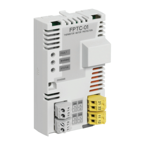
- Page 1 — OPTIONS FOR ABB DRIVES FPTC-01 thermistor protection module (option +L536) for ACS880 drives User's manual...
- Page 3 FPTC-01 thermistor protection module (option +L536) for ACS880 drives User's manual Table of contents 1. Safety instructions 5. Mechanical installation 6. Electrical installation 8. Start-up and validation test 3AXD50000027750 Rev D EFFECTIVE: 2020-11-18...
-
Page 5: Table Of Contents
Table of contents 5 Table of contents 1 Safety instructions Contents of this chapter ............Use of warnings and notes ............Instructions for functional safety circuits ........Electrical safety precautions ............. 2 Introduction to the manual Contents of this chapter ............Applicability ................ - Page 6 6 Table of contents Fault reaction function ............... FPTC-01 module ..............STO function in the drive/inverter ........FSO module ............... 5 Mechanical installation Contents of this chapter ............Necessary tools and instructions ..........Unpacking and examining the delivery ........Installing the module ..............
- Page 7 Validation test reports ............Validation test ................9 Fault tracing Contents of this chapter ............Reporting problems and failures related to safety functions ..FPTC-01 module replacement ..........Fault and warning messages ............ LEDs ..................10 Maintenance Contents of this chapter ............
- Page 8 8 Table of contents Safety block diagrams ............... Two-channel configurations ..........One-channel configurations ..........Response times ................ Relevant failure modes ............. Related standards and directives ..........Compliance with the European Machinery Directive ....TÜV Nord certificate ..............Further information...
-
Page 9: Safety Instructions
Safety instructions 9 Safety instructions Contents of this chapter This chapter contains the safety instructions which you must obey when you install, operate and do maintenance on the safety functions of a drive. Use of warnings and notes Warnings tell you about conditions which can cause injury or death, or damage to the equipment. -
Page 10: Instructions For Functional Safety Circuits
10 Safety instructions WARNING! General warning tells about conditions, other than those caused by electricity, which can cause injury or death, or damage to the equipment. WARNING! Electrostatic sensitive devices warning tells you about the risk of electrostatic discharge which can cause damage to the equipment. - Page 11 Safety instructions 11 • for ACS880 liquid-cooled multidrives, multidrive modules and single drive modules, see ACS880 liquid-cooled multidrive cabinets and modules safety instructions (3AXD50000048633 [English]). WARNING! The safety function described in this manual does not isolate the main circuit or auxiliary circuit from the power supply. Do not do work on the drive, motor cable or motor before you have isolated the drive system from all power supplies and measured that there are no dangerous voltages.
-
Page 12: Electrical Safety Precautions
12 Safety instructions Electrical safety precautions These electrical safety precautions are for all personnel who do work on the drive, motor cable or motor. WARNING! Obey these instructions. If you ignore them, injury or death, or damage to the equipment can occur. If you are not a qualified electrical professional, do not do installation or maintenance work. - Page 13 Safety instructions 13 5. Measure that the installation is de-energized. • Before and after measuring the installation, verify the operation of the voltage tester on a known voltage source. • Make sure that the voltage between the drive input power terminals (L1, L2, L3) and the grounding (PE) busbar is zero.
-
Page 15: Introduction To The Manual
Introduction to the manual Contents of this chapter This chapter gives basic information on the manual. Applicability This manual is applicable to the FPTC-01 module and to the Safe motor temperature safety (SMT) function which uses the FPTC-01 module (option +L536). Compatibility The FPTC-01 module is compatible with: •... -
Page 16: Target Audience
• ACS880-107/107LC inverter units • FSO-12 and FSO-21 safety functions modules • ACS880 primary control program version 2.10 or later. For the compatibility of other control programs, contact your local ABB representative. Target audience This manual is intended for people who plan the installation, install, start up, use and service the module. - Page 17 Introduction to the manual 17 Name Code ACS880-04 drive modules (200 to 710 kW, 300 to 700 3AUA0000128301 hp) hardware manual ACS880-04 single drive module packages (560 to 2200 3AUA0000138495 kW) hardware manual ACS880-04F drive modules hardware manual 3AXD50000034664 ACS880-04XT drive module packages (500 to 1200 3AXD50000025169 kW) hardware manual ACS880-04FXT drive module packages hardware...
-
Page 18: Terms And Abbreviations
FSO-12 safety functions module user's manual 3AXD50000015612 FSO-21 safety functions module user’s manual 3AXD50000015614 FSE-31 pulse encoder interface module user’s manual 3AXD50000016597 FPTC-01 thermistor protection module (option +L536) 3AXD50000027750 user’s manual Manuals and quick guides for I/O extension modules, fieldbus adapters, etc. www.abb.com/drives/documents for all manuals on the Internet. - Page 19 Types of protection, increased safety (IEC/EN 60079-7) Ex motors Motors used in explosive atmospheres FEA-03 Optional I/O extension adapter FPTC-01 Optional thermistor protection module FSE-31 Optional pulse encoder interface module for safety encoder FSO-21 Safety functions module which supports the FSE-31 module...
- Page 20 20 Introduction to the manual Term Description Safety integrity level (1...3) (IEC 61508) SILCL Maximum SIL (level 1...3) that can be claimed for a safety function or subsystem (IEC/EN 62061) Safe motor temperature (IEC/EN 61800-5-2) Safe stop 1 (IEC/EN 61800-5-2) Safe stop emergency Safe torque off (IEC/EN 61800-5-2) Stop category...
-
Page 21: Hardware Description
Contents of this chapter This chapter gives a short description of the module. Product overview The FPTC-01 module together with the drive/inverter STO implements the Safe motor temperature (SMT) safety function as defined in IEC/EN 61800-5-2. Inside the module, there is reinforced insulation between the motor thermistor connection and the other terminals of the module. -
Page 22: Operation Basics
When the motor temperature increases above the PTC sensor temperature limit, the sensor resistance increases sharply. The FPTC-01 module sends a warning indication to the drive. The XWRN input is not safety-related and does not activate the drive STO function. -
Page 23: Layout
Hardware description 23 ■ Layout XSTO2 XWRN XSTO1 XFLT Retaining clips Lock Diagnostics LEDs Mounting screw... -
Page 24: Markings
2-pin detachable terminal block for STO output 1 XSTO2 2-pin detachable terminal block for STO output 2 Markings The type designation label is attached to the back of the FPTC-01 module. An example label and description of the label contents are shown below. Type... -
Page 25: Option Description And Instructions
Contents of this chapter This chapter describes the Safe motor temperature function implemented with the FPTC-01 module and the drive Safe torque off function and gives instructions for the user. Overview To implement the Safe motor temperature (SMT) function, you can connect the FPTC-01 module directly to the drive Safe torque off (STO) circuit, or you can use it together with an FSO module. -
Page 26: Wall-Mounted Drives, Drive Modules And Inverter Modules
26 Option description and instructions Note: The Safe motor temperature function is motor-specific. This is the case also in ACS880 multidrives where multiple motors are connected to the drive. ■ Wall-mounted drives, drive modules and inverter modules The option module is available as a factory-installed option (+L536) or as an add-on kit for ACS880 wall-mounted drives, drive modules and inverter modules. -
Page 27: Commissioning The Drive For A Motor In A Hazardous Area
When the XWRN input detects a motor overtemperature situation, the FPTC-01 module generates a warning to the drive. This is not a safety-related function, and does not need a reset. -
Page 28: Fault Reaction Function
Fault reaction function ■ FPTC-01 module The FPTC-01 module has a fault reaction function. When the module detects an internal fault or a fault in the temperature sensor circuit, it sends a request to the drive control unit to stop modulation, and... -
Page 29: Sto Function In The Drive/Inverter
Option description and instructions 29 ■ STO function in the drive/inverter The STO function in the drive/inverter has internal fault diagnostics and a fault reaction function. The fault reaction function causes a fault trip if it detects a redundancy fault of STO control signals or an internal failure. -
Page 31: Mechanical Installation
• Torx screwdriver (T10) For a complete list of tools, see the applicable drive hardware manual. Unpacking and examining the delivery 1. Open the option package. 2. Make sure that the package contains: • FPTC-01 module • STO cable • this manual. -
Page 32: Installing The Module
32 Mechanical installation 3. Make sure that there are no signs of damage to the items. Installing the module WARNING! Obey the safety instructions of the drive. If you ignore them, injury or death, or damage to the equipment can occur. - Page 33 Mechanical installation 33 Do not install the FPTC-01 module on an FEA-03 F-series extension adapter. The diagnostics of the module requires that you install it directly on the control unit.
-
Page 35: Electrical Installation
Electrical installation 35 Electrical installation Contents of this chapter This chapter contains instructions on wiring the module. Warnings WARNING! Obey the safety instructions of the drive. If you ignore them, injury or death, or damage to the equipment can occur. If you are not a qualified electrical professional, do not do installation or maintenance work. -
Page 36: Necessary Tools And Instructions
3. Install the drive or inverter unit, including the components of the motor thermal protection function, outside the potentially explosive atmosphere. 4. For the sensor connection, ABB recommends to use shielded twisted-pair cable. This type of cable decreases electromagnetic interference in the sensor circuit. -
Page 37: Terminal Designations
Electrical installation 37 5. Route the sensor cables away from the motor cable. Power cables can cause electromagnetic interference in the sensor circuit. 6. Ground all sensor cable shields to a single grounding point outside the potentially explosive atmosphere. 360-degree grounding of the cable shields at the cable entry of the drive is recommended. -
Page 38: Xwrn Input
Note: If you do not connect a PTC sensor or resistor to the XWRN input, the WARNING LED of the module stays on. Wiring examples This section shows five methods to connect the FPTC-01 module to the drive. If you use a one-channel connection, make sure that you can reach the required safety integrity level (SIL). - Page 39 Wiring example 3 (page 42): An external safety relay is connected between the FPTC-01 module and the drive STO inputs with a two-channel connection. Wiring example 4 (page 43): The STO outputs of the FPTC-01 module are connected directly to the STO terminals of the drive with a one-channel connection.
-
Page 40: Wiring Example 1
40 Electrical installation ■ Wiring example 1 This connection is SIL2 capable (redundancy between STO channels). FPTC XSTO XSTO1 SGND XSTO2 XFLT SLOT X100 1/2/3 Ex M Control unit Potentially explosive atmosphere If necessary, you can also connect an external device (for example, an emergency stop button) between the XSTO input of the control unit and the XSTO1 and XSTO2 outputs of the FPTC module. -
Page 41: Wiring Example 2
Electrical installation 41 ■ Wiring example 2 With an FSO module, two-channel connection. This connection is SIL2 capable (redundancy between STO channels). FPTC XSTO XSTO1 SGND XSTO2 XFLT SLOT X100 1/2/3 X111 Ex M X113 X114 Control unit Potentially explosive atmosphere... -
Page 42: Wiring Example 3
42 Electrical installation ■ Wiring example 3 With an external safety relay, two-channel connection. This connection is SIL2 capable (redundancy between STO channels). FPTC XSTO XSTO1 SGND XSTO2 XFLT SLOT X100 1/2/3 Ex M Control unit External safety relay Potentially explosive atmosphere... -
Page 43: Wiring Example 4
Electrical installation 43 ■ Wiring example 4 One-channel connection. This connection is SIL1 capable (no redundancy between STO channels). FPTC XSTO XSTO1 SGND XSTO2 XFLT SLOT X100 1/2/3 Ex M Control unit Potentially explosive atmosphere If necessary, you can also connect an external device (for example, an emergency stop button) between the XSTO input of the control unit and the XSTO2 output of the FPTC module. -
Page 44: Wiring Example 5
44 Electrical installation ■ Wiring example 5 With an FSO module, one-channel connection. This connection is SIL1 capable (no redundancy between STO channels). FPTC XSTO XSTO1 SGND XSTO2 XFLT SLOT X100 1/2/3 X111 Ex M X113 X114 Control unit Potentially explosive atmosphere... -
Page 45: Parameter Settings
Parameter settings 45 Parameter settings Contents of this chapter This chapter contains the drive and FSO module parameter settings. Drive / inverter Use the Drive composer PC tool or the control panel to set the parameter values. - Page 46 This parameter value does not have an ef- fect on the SMT function, but this is the re- commended setting. For cabinet-built drives, ABB sets this value at the factory. 35.30 FPTC configuration Activates FPTC modules installed on the word control unit of the drive.
-
Page 47: Switching Frequency Limitation
EX motor 1 = The driven motor is an Ex motor provided by ABB for potentially explosive atmospheres. This sets the required minim- um switching frequency for ABB Ex motors. For non-ABB Ex motors, contact your local ABB representative. ■... -
Page 48: Other Recommended Settings
48 Parameter settings For ABB Ex motors, use parameter 95.15 to set the required minimum switching frequency. For more information, see the drive firmware manual. For Ex motors supplied by other motor manufacturers, contact the motor manufacturer for the correct value and your local ABB representative for instructions on how to make the parameter setting in the drive. - Page 49 Parameter settings 49 You must use the Drive composer pro PC tool to set the FSO module parameters. You also need a password to be able to download the configuration to the FSO module from Drive composer pro. For the default password of the FSO module, see the applicable FSO module user’s manual.
-
Page 50: General Parameters
50 Parameter settings Note: Setting parameters related to STO and SSE can also have an effect on other safety functions. You must take all safety functions into consideration when you configure the FSO module. See the applicable FSO module user’s manual and safety option user's manual. -
Page 51: Parameters For The Sto Function
Parameter settings 51 Index Name Example Description value FSO- Power-up ac- Automatic Sets the power-up acknowledgement GEN.41 knowledge- method of the FSO module. ment Automatic: You do not need to push a reset button after switching on the FSO module. The FSO module generates the acknowledgement signal automat- ically after the power-up. - Page 52 52 Parameter settings overtemperature situations. Also, the FSO module can activate the STO function in fault situations. Index Name Example Description value STO.02 STO acknow- Sets the acknowledgement method Automat- ledgement used in the STO, SSE and SS1 func- ic 1) tions.
- Page 53 Parameter settings 53 Index Name Example Description value STO.14 Time to zero 2000 ms Sets the time that is needed to coast speed with the motor to a standstill from maximum STO and mod- process speed. If this time is not known, it can be measured with Drive composer pro PC tool when an encoder is used for motor control (otherwise you...
-
Page 54: Parameters For The Sse Function
54 Parameter settings Index Name Example Description value I/O settings SAFEIO.36 DI X113:4 diag Sets the diagnostic pulse of digital input On 2) pulse on/off X113:4 on or off. On: The input monitors that it receives test pulses. Off: The input does not monitor for test pulses. -
Page 55: Fse Module And Safety Encoder Parameters
Parameter settings 55 manual do not use this function, but the FSO module can activate the SSE function in internal fault situations. Index Name Example Description value SSE.13 SSE function Sets the type of the SSE function. Immediate Immediate STO: The FSO module STO 1) activates the drive STO function immediately after the SSE request (stop... - Page 56 56 Parameter settings Index Name Example Description value 200.232 Number of en- Single en- Shows the number of safety encoders coders coder CH1 connected to the FSE module. S_ENC- Safe pulse en- Version 1 Activates the safety encoder and shows GEN.01 coder version the version parameter group S_ENC-...
-
Page 57: Notes
Parameter settings 57 Index Name Example Description value 91.12 Module 1 loca- Sets the slot in which the safety en- tion coder interface module 1 is located. 92.01 Encoder 1 type HTL1 Activates or deactivates the communic- ation with the safety encoder interface module 1 and sets the type for the safety encoder. -
Page 58: Mechanical Brake Control
58 Parameter settings emergency stop reset button. The user must also reset the FSO module with the emergency stop reset button after motor overtemperature situations. The indication lamp on the reset button is on. Do not change this setting. Mechanical brake control If you use a mechanical brake with the motor thermal protection circuit, pay special attention to the control of the mechanical brake. -
Page 59: Start-Up And Validation Test
Start-up and validation test 59 Start-up and validation test Contents of this chapter This chapter describes the start-up, validation test procedure, and validation of the safety function. Validation of the safety functions You must do a validation test to validate the correct operation of safety functions. -
Page 60: Validation Procedure
60 Start-up and validation test ■ Validation procedure If you use an FSO module in the safety system, you must validate the general settings of the FSO module and the safety encoder (if used) before you validate the safety function. See the FSO module user's manual, chapter Verification and validation. -
Page 61: Validation Test
Start-up and validation test 61 • a list of all safety functions that are used in the safety application • a list of all safety-related parameters and their values • documentation of start-up activities, references to failure reports and resolution of failures •... - Page 62 Settings with voltage connected Make sure that you have activated the FPTC-01 module in the correct slot (parameter 35.30). Make sure that you have set all the necessary parameters for the safety function.
- Page 63 Start-up and validation test 63 Action Start the drive and make sure that the motor is running. Do an overtemperature monitoring test: increase the resistance in the XFLT input to more than 4 kohm (for example, open the circuit by dis- connecting the wires).
- Page 64 64 Start-up and validation test Action If you use an FSO module, save the FSO safety file (button Save safety file in the Drive composer pro PC tool). Fill in and sign the validation test report. Store the report in the logbook of the machine.
-
Page 65: Fault Tracing
LEDs on the module. Reporting problems and failures related to safety functions Contact ABB. FPTC-01 module replacement If there is a failure in the FPTC-01 module, you must replace it with a new one. Do not try to repair the module. -
Page 66: Fault And Warning Messages
The last digit of the auxiliary code identifies the slot. 4991 The FPTC-01 module in Safe motor 1. Make sure that the option slot 1 indicates temperature motor has sufficient overtemperature in the 1 1) cooling. - Page 67 Fault tracing 67 Code Name Cause Action (hex) Warnings A497 The FPTC module in Motor 1. Make sure that the option slot 1 has activated temperature motor has sufficient a motor temperature cooling. warning in the XWRN input (non-safety related). 2.
-
Page 68: Leds
68 Fault tracing LEDs The FPTC-01 module has three diagnostic LEDs. Name Color Description FAULT The motor temperature is outside the permitted temperature range and the drive STO is active, or there is no PTC sensor connected to the XFLT input (safety-related). -
Page 69: Maintenance
After the safety function is validated, it must be maintained by periodic proof testing. If you change the wiring or a component after the start-up, replace the FPTC-01 module, modify parameters, or restore parameters to their factory default values: • Use only ABB-approved spare parts. -
Page 70: Proof Test
12 months. This is a recommendation and depends on the required (not achieved) SIL/PL. For example, contactors, breakers, safety relays, contactor relays, emergency stop buttons, switches, etc. are typically safety devices which have electromechanical outputs. The FPTC-01 module,... -
Page 71: Competence
Maintenance 71 the FSO module and the STO circuit of the drive do not have electromechanical outputs. Competence The person who does the maintenance and proof test activities of the safety function must be a competent person with expertise and knowledge of the safety function and functional safety, as required by IEC 61508-1 clause 6, and Ex regulations. -
Page 73: Technical Data
Technical data 73 Technical data Contents of this chapter This chapter contains the technical data of the module, gives general rules, notes and definitions related to safety functions and lists the related standards and directives. The safety data, relevant certificates and Declarations of Conformity are also included. -
Page 74: Dimension Drawing
74 Technical data Dimension drawing The dimensions are shown in millimeters and inches. Isolation areas The following figure shows the different isolation areas of the module. Isolation areas A and B and the mounting screw are connected to... - Page 75 Technical data 75 ground. Isolation area C is in the same potential as the PTC sensor element in the motor. XSTO1 XSTO2 XWRN XFLT Connection to the drive Mounting screw, chassis PTC Warning PTC Fault STO 1 STO 2 There is reinforced insulation between: •...
-
Page 76: Connections
76 Technical data Connections ■ Motor thermistor connection • Maximum wire size: 2.5 mm (14 AWG) • Maximum wire length: 700 m (2300 ft) (1400 m [4600 ft] for the whole loop) With the specified cable type, detection of a short-circuited PTC sensor or cable is not guaranteed after 100 m (328 ft). -
Page 77: Ambient Conditions
Safety data The FPTC-01 module is a type A safety component as defined in IEC 61508-2. For the types of the drive/inverter STO and the FSO module, see the applicable hardware manual or FSO user's manual. -
Page 78: Safety Block Diagrams
= 5 a DC (%) Cat. 3AXD10000454332 F The MTTF value (EN ISO 13849-1) of the FPTC-01 module: • 1697 years (two-channel connection) • 1703 years (one-channel connection) Safety block diagrams The components that are included in the safety data calculations are shown in the safety block diagrams below. -
Page 79: Two-Channel Configurations
Technical data 79 ■ Two-channel configurations This diagram is applicable to configuration 1. See Wiring example 1 (page 40). PTC sensor FPTC module Drive STO This diagram is applicable to configuration 2. See Wiring example 2 (page 41). PTC sensor FPTC module FSO module (and FSE-31 module, if used) Drive STO... -
Page 80: One-Channel Configurations
80 Technical data This diagram is applicable to configuration 3. See Wiring example 3 (page 42). PTC sensor FPTC module External safety relay Drive STO Note: The failure rate of the external safety relay is not included in the calculation. ■... -
Page 81: Response Times
Response times • FPTC-01 module: less than 10 ms • SMT function: the response time of the PTC sensor + FPTC-01 module (<10 ms) + FSO module (<50 ms) + drive STO (<50 ms) Relevant failure modes • The SMT function activates when not necessary (safe failure) •... -
Page 82: Related Standards And Directives
82 Technical data Related standards and directives IEC 61508:2010 Functional safety of electrical/electronic/programmable electronic safety-related systems. Part 1 – General Requirements Part 2 – Requirements for electrical/electronic/program- mable electronic safety-related systems EN 61800-5- Adjustable speed electrical power drive systems – Part 5- 2:2007 2: Safety requirements –... - Page 83 Technical data 83 this manual (option +L536) is in the scope of the Machinery Directive as a safety component. This function complies with European harmonized standards such as IEC/EN 61800-5-2. The declaration of conformity is included in the documentation delivered with the drive.
-
Page 84: Tüv Nord Certificate
84 Technical data TÜV Nord certificate The TÜV Nord certificate for the FPTC-01 module and ACS880 drive series is shown below. - Page 85 Address any inquiries about the product to your local ABB representative, quoting the type designation and serial number of the unit in question. A listing of ABB sales, support and service contacts can be found by navigating to www.abb.com/searchchannels. Product training For information on ABB product training, navigate to new.abb.com/service/training.
- Page 86 3AXD50000027750D © Copyright 2020 ABB. All rights reserved. Specifications subject to change without notice.