Table of Contents
Advertisement
Quick Links
Advertisement
Table of Contents

Related Manuals for ABB FSO-12


Summary of Contents for ABB FSO-12
- Page 1 — OPTIONS FOR ABB DRIVES FSO-12 safety functions module User’s manual...
- Page 2 Drive firmware manuals and guides ACS880 primary control program firmware manual 3AUA0000085967 Option manuals and guides ACX-AP-x assistant control panels user’s manual 3AUA0000085685 FSO-12 safety functions module user's manual 3AXD50000015612 FENA-01/-11/-21 Ethernet adapter module user’s manual 3AUA0000093568 FPNO-21 PROFINET adapter module user's manual 3AXD50000158614 Manuals and quick guides for I/O extension modules, fieldbus adapters, etc.
- Page 3 User’s manual FSO-12 safety functions module Table of contents 1. Safety instructions 8. Installation 12. Start-up 2020 ABB. All Rights Reserved. 3AXD50000015612 Rev H EFFECTIVE: 2020-07-24...
-
Page 5: Table Of Contents
Table of contents 5 Table of contents 1. Safety instructions Contents of this chapter ............13 Use of warnings . - Page 6 6 Table of contents Connections ............41 Type designation label .
- Page 7 Configuring the ABB AC500-S Safety PLC ........
- Page 8 8 Table of contents Power supply connection/cables ......... . 203 Ensuring the EMC compatibility .
- Page 9 FSO-12 parameters ........
- Page 10 10 Table of contents Purpose of the validation testing ..........327 Preconditions for validation testing .
- Page 11 Table of contents 11 Drive control board boot ........... . 369 Updates .
- Page 12 12 Table of contents...
-
Page 13: Safety Instructions
Safety instructions 13 Safety instructions Contents of this chapter The chapter contains the warning symbols used in this manual and the safety instructions which you must obey when you install or connect an option module to a drive or inverter. If you ignore the safety instructions, injury, death or damage can occur. -
Page 14: Electrical Safety Precautions
14 Safety instructions Electrical safety precautions These instructions are for all who install or connect an option module to a drive and need to open its front cover or door to do the work. WARNING! Obey these instructions. If you ignore them, injury or death, or damage to the equipment can occur. -
Page 15: Introduction To The Manual
The manufacturer of the machinery always remains ultimately responsible for the product safety and compliance with applicable laws. ABB does not accept any liability for direct or indirect injury or damage caused by the information contained in this document. ABB hereby disclaims all liabilities that may result from this document. -
Page 16: Compatible Products
Additional safety functions (not specified in EN/IEC 61800-5-2): • Safe stop emergency (SSE), see page • Safe maximum speed (SMS), see page • Prevention of unexpected start-up (POUS), see page 132. Note: The FSO-12 module does not support an encoder in safety applications. -
Page 17: Target Audience
PROFIsafe profile of PROFINET. It describes the FSO module states and transitions and the contents of the PROFIsafe messages. The chapter also includes installation instructions, configuration instructions for the ABB AC500-S Safety PLC and Siemens SIMATIC Fail-safe S7 PLC as well as fault tracing tips. - Page 18 18 Introduction to the manual Chapter Planning for installation (page 201) gives instructions and references to instructions in other manuals for planning the safety system installation, as well as the requirements for installation in the applicable safety standards. Chapter Installation (page 209) gives examples of how to connect the FSO module to the ACS880.
-
Page 19: Recommended Reading
Introduction to the manual 19 Recommended reading This manual is based on the following standards. It is recommended that you are familiar with these standards before implementing safety-related systems. • EN/IEC 61800-5-2: Adjustable speed electrical power drive systems – Part 5-2: Safety requirements –... - Page 20 20 Introduction to the manual Term / Description Abbreviation Common cause Failure, which is the result of one or more events, causing coincident failure (CCF) failures of two or more separate channels in a multiple channel (redundant architecture) subsystem, leading to failure of a Safety related electronic control function (SRCF).
- Page 21 Failure in time: 1E-9 hours. Expected failure rate of semiconductors and other electronic devices. (IEC 61508) FPNO-21 PROFINET fieldbus adapter module FSO-12 Safety functions module which does not support the use of encoders Functional safety Functional safety is part of the overall safety that depends on a system or equipment operating correctly in response to its inputs.
- Page 22 22 Introduction to the manual Term / Description Abbreviation Normally closed. Break contact. Normally closed contacts disconnect the circuit when the relay is energized; the circuit is connected when the relay is de-energized. Normally open. Make contact. Normally open contacts connect the circuit when the relay is energized;...
- Page 23 Introduction to the manual 23 Term / Description Abbreviation Risk Combination of the probability of occurrence of harm and the severity of that harm Safe state STO activated. The STO circuit in the drive is open. Note: When the drive STO is activated in the POUS function, the FSO is in the Operational state.
- Page 24 24 Introduction to the manual Term / Description Abbreviation Safely-limited speed Safe maximum speed Safe stop 1 SS1-r Safe stop 1 ramp monitored SS1-t Safe stop 1 time controlled Safe stop emergency For example, safety fieldbus failure, speed monitoring trip limit hit (SLS and SMS) will activate the SSE safety function.
-
Page 25: Certificates
Dangerous failure rate, undetected failures λ Safe failure rate Certificates TÜV Nord certificate for the FSO-12 and ACS880 drive series can be found in the ABB Library, where you can also check the validity of the certificate with a specific drive variant. - Page 26 26 Introduction to the manual The PROFIsafe certificate for the FSO-12 module is attached below.
-
Page 27: Safety Information And Considerations
Safety information and considerations 27 Safety information and considerations Contents of this chapter This chapter contains general safety considerations and information to be taken into account when applying the FSO safety functions. WARNING! The FSO safety functions module is delivered with the safety functions bypassed by jumper wires in connectors X:113 and X:114 to allow initial drive commissioning without the need to configure safety functions first. -
Page 28: Responsibilities
If you detect any failure in safety functions, contact your local ABB representative. Intentional misuse Use the FSO module according to the instructions given in the user’s manual. ABB is not responsible for any damage caused by the misuse of the module. -
Page 29: I/O
Note: ABB recommends to use external devices which are equipped with either a positive mechanical action or force guided contacts. -
Page 30: Acknowledgement
FSO module needs motor speed feedback to perform safety functions. It can be either a measured speed from a safety encoder or a safe speed estimate. With FSO-12 module only safe speed estimate is available. Depending of the motor speed feedback, safety functions operate slightly differently (for example, when the indications turn on and off) due to inaccuracy in safe speed estimate. - Page 31 Safety information and considerations 31 Safe speed estimate With safe speed estimate, the FSO module uses the drive output frequency measurement to estimate the motor speed. The FSO module has two safe speed estimation data channels. Speed in channel one is received from the drive (200.01 FSO speed ch1), and speed in channel two is calculated by FSO module...
- Page 32 32 Safety information and considerations enough by coasting, the rotation must be stopped with external device, for example with a safe brake. It is not allowed to use the safe speed estimation with an external active load that can accelerate the motor shaft. For example, in a hoist drive, the hanging load would potentially cause an accelerating motion because of the gravity, thus the safe speed estimate cannot be used for these types of applications.
- Page 33 Safety information and considerations 33 During the deceleration, when the motor torque is -100%, the motor slip is again in its maximum value. Because of the torque direction, FSO speed estimates are below the actual motor speed (amount of the slip). After the FSO safe speed estimates reach 0 rpm, they begin to show reverse (negative) motor speed due to the negative motor slip.
-
Page 34: Proof Testing
34 Safety information and considerations Transient mute time, example graph The graph below illustrates the behavior of the safe speed estimate in the transient situations of an example application. There are spikes in the FSO module safe speed data when the motor speed changes due to change in the motor torque. Motor speed Time SLS trip limits... -
Page 35: Safety Separation
Safety information and considerations 35 External contactors, relays and mechanical actuators must be sized correctly for safety use as the automatic diagnostics only monitors the electrical connections; the mechanical final elements like brakes are not diagnosed. Failure of a mechanical actuator, for example a brake, could lead up to an undetected fault, and a possible loss of the load control. - Page 36 36 Safety information and considerations...
-
Page 37: Overview
Overview 37 Overview Contents of this chapter This chapter briefly describes the FSO module with safety system components as well as the FSO module layout, connections, type designation label and operational characteristics. -
Page 38: System Description
FSO module. FSO module and safety system components Example figure of a safety system with the FSO-12 safety functions module, the ACS880-01 drive, a safety PLC, the FENA-21 module, switches and buttons. PROFIsafe over PROFINET Safety PLC... -
Page 39: Fso Module Version Handling
Both the FSO module and the ACS880 drive firmware must support the used safety functions. You can always replace the FSO-12 module with a newer revision and use the same configuration file with the new revision. Each time you make any changes in the... -
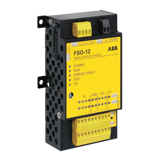
Page 40: Layout
40 Overview Layout No Description 24 V DC input connection Safe torque off (STO) connection Data connection Mounting for drives with ZCU-12 control unit shown. Two mounting points on each side. The screw fixed at 4b also grounds the enclosure of the FSO. Mounting points for drives with other control units may vary. -
Page 41: Connections
Connections The FSO module has several safety I/Os for external safety devices, for example buttons, gates and indicators. The FSO-12 module does not have the ability to interface to an encoder. When you use the Safe brake control (SBC) function, the FSO module controls the mechanical brake. -
Page 42: Operational Characteristics
42 Overview Operational characteristics The FSO module monitors that the drive operates within the configured operating limits, and if the limits are exceeded, activates a safe stopping in the drive within the response time. The safe stopping function activates the drive STO function either immediately or after an emergency ramp. -
Page 43: Safe Torque Off (Sto)
Overview 43 Safe torque off (STO) This safety function activates the STO function in the drive, this is, opens the STO circuit in the drive. The motor coasts to a stop (stop category 0). See section function on page 56. ... -
Page 44: Safely-Limited Speed (Sls)
44 Overview information, see section Safe stop emergency (SSE) on page 76). Make sure that you dimension the brake correctly for these situations. SS1 function and SSE with emergency ramp In these safety functions, you can configure the SBC and STO combination to be activated at a user-defined speed limit while ramping down to zero speed. -
Page 45: Safety Functions
Safety functions 45 Safety functions Contents of this chapter This chapter describes how the safety functions of the FSO module operate. The FSO-12 module supports these safety functions: Safety function Stop category Information Page Safe torque off (STO) Stop category 0 STO: standard drive feature... -
Page 46: General
46 Safety functions General Safety function request A safety function can be activated locally from FSO digital inputs, from a safety PLC, in FSO internal fault situations or by another safety function (see section Dependencies between safety functions on page 134). If you want to control a safety function with a push button, connect an activation button to an FSO digital input. - Page 47 Safety functions 47 The acknowledgement method can be manual or automatic, from a safety PLC via the PROFIsafe communication bus, or either manual or from a safety PLC. • Automatic: The FSO module acknowledges the start-up and/or safety functions automatically when this has completed successfully and the safety function request has been removed.
-
Page 48: Dc Magnetization And Drive Start Modes
48 Safety functions Note: If an SSE or SS1 request is received while the STO function is active, the STO function must be completed before the acknowledgement is allowed. For more information see section Safe torque off (STO) on page 55. •... -
Page 49: Ramp Monitoring
Safety functions 49 Ramp monitoring The ramp monitoring is configured with five parameters as described below. Ramp monitoring using the ramps Defining the ramp monitoring limits Speed Speed Motor speed Limit hit Ramp monitoring started * Lower monitoring limit is always 30 rpm below actual speed.Starting point of the upper monitoring limit is based on maximum deceleration slope (E/C) and D. -
Page 50: Function Indications
50 Safety functions Limit hit: If the motor speed hits a ramp monitoring limit, the FSO module activates the STO function and generates an event. The user can select the event type (warning, fault or event) with parameter FSOGEN.62 STO indication safety limit. -
Page 51: Fso Modes
Safety functions 51 FSO modes The FSO can be in one of the following modes: • Power down: The power to the FSO is off. The drive STO circuit is open. The POWER LED is off. • Start-up: The FSO is starting up after power-up. Indicated with a blinking green RUN LED. -
Page 52: Transitions Between Fso Modes And States
52 Safety functions Transitions between FSO modes and states The following diagram shows the possible transitions during normal operation of the FSO module. • Power down: STO active, power off (below 19 V) • Start-up: STO active, power on (above 19 V), start-up checks performed •... -
Page 53: Cascade
Safety functions 53 At power-up, the FSO goes into the Start-up mode; it performs start-up checks and, according to the configuration, enters the Operational state either automatically or after an acknowledgement request from the FSO I/O or from a safety PLC. The Drive composer pro PC tool can request the Configuration mode, when the FSO is in the Start-up, Operational, Safe or Fail-safe mode and the drive is in the Torque off mode (not modulating). - Page 54 54 Safety functions This figure shows an example cascade configuration. Two different safety functions are cascaded in the same cascaded system. Acknowledgement Automatic acknowledgement Emergency stop X114:2 Follower Master Follower X113:1 X114:1 X113:7 Safety Safety Safety Safety Safety Safety function 1 function 1 function function...
-
Page 55: Safe Torque Off (Sto)
Safety functions 55 Safe torque off (STO) The STO function brings the machine safely into a no-torque state and/or prevents it from starting accidentally. The STO function in the FSO module activates the drive STO function, that is, opens the STO circuit in the drive. This prevents the drive from generating the torque required to rotate the motor. -
Page 56: Sto Function
56 Safety functions STO function The operation of the STO function when the SBC is not used is described in the time diagram and table below. For configuration, see section How to configure STO page 234. Motor speed STO.14 STO.13 Time STO request... -
Page 57: Sbc After Sto
Safety functions 57 SBC after STO The operation of the SBC after the STO function (positive SBC delay) is described in the time diagram and table below. For configuration, see section How to configure SBC after STO on page 235. Motor speed SBC.12 SBC.13... - Page 58 58 Safety functions Step Description The STO request is received (for example, from the I/O). The FSO activates the drive STO and starts counters for times A and C. After time C has elapsed, the acknowledgement becomes allowed as soon as the STO request has been removed (step 5).
-
Page 59: Sbc Before Sto
Safety functions 59 SBC before STO The operation of the SBC before the STO function (negative SBC delay) is described in the time diagram and table below. For configuration, see section How to configure SBC before STO on page 236. The reason to use a negative SBC delay is to have the mechanical brake closed just before the drive STO circuit is opened. - Page 60 60 Safety functions Step Description The STO request is received (for example, from the I/O). The FSO activates the SBC function (brake) and starts counters for times A and B. After time C has elapsed, the SBC starts to brake the motor. After time A has elapsed, the FSO activates the drive STO.
-
Page 61: Safe Stop 1 (Ss1)
Safety functions 61 Safe stop 1 (SS1) The SS1 function stops the motor safely by ramping down the motor speed. The FSO activates the drive STO function below a user-defined zero speed limit. The FSO monitors the stop ramp either with the time or ramp monitoring method (SS1 function types SS1-t and SS1-r, respectively). -
Page 62: Ss1 With Time Monitoring (Ss1-T)
62 Safety functions SS1 with time monitoring (SS1-t) The operation of the SS1 with time monitoring (SS1-t) is described in the time diagram and table below. For configuration, see section How to configure SS1 with time monitoring (SS1-t) on page 237. Motor speed SS1.14 - ->... - Page 63 Safety functions 63 Step Description The SS1 request is received (for example, from the I/O). The FSO starts a counter for time A. After time C has elapsed, the drive starts to ramp down the motor speed. SAR1 parameter 200.112 defines the deceleration ramp.
-
Page 64: Ss1 With Ramp Monitoring (Ss1-R)
64 Safety functions SS1 with ramp monitoring (SS1-r) The operation of the SS1 with ramp monitoring (SS1-r) is described in the time diagram and table below. For configuration, see section How to configure SS1 with ramp monitoring (SS1-r) on page 239. Motor speed - ->... - Page 65 Safety functions 65 Step Description The SS1 request is received (for example, from the I/O). After time B has elapsed, the drive starts to ramp down the motor speed. SAR1 parameter 200.112 defines the deceleration ramp. The FSO starts the SAR1 ramp monitoring (parameters SARx.21 and SARx.22).
-
Page 66: Ss1 With Speed Limit Activated Sbc
66 Safety functions SS1 with speed limit activated SBC In these examples, the SBC and drive STO functions are activated at a user-defined speed limit. With time monitoring (SS1-t) The operation of the SS1-t function with speed limit activated SBC is described in the time diagram and table below. - Page 67 Safety functions 67 Step Description The SS1 request is received (for example, from the I/O). The FSO starts a counter for time B. After time D has elapsed, the drive starts to ramp down the motor speed. SAR1 parameter 200.112 defines the deceleration ramp.
- Page 68 68 Safety functions With ramp monitoring (SS1-r) The operation of the SS1-r function with speed limit activated SBC is described in the time diagram and table below. For configuration, see section How to configure SS1 with speed limit activated SBC on page 240.
- Page 69 Safety functions 69 Step Description The SS1 request is received (for example, from the I/O). After time C has elapsed, the drive starts to ramp down the motor speed. SAR1 parameter 200.112 defines the deceleration ramp. The FSO starts the SAR1 ramp monitoring (parameters SARx.21 and SARx.22).
-
Page 70: Ss1 With Speed Limit Activated Sbc, Sbc Before Sto
70 Safety functions SS1 with speed limit activated SBC, SBC before STO In these examples, the SBC function is activated at a user-defined speed limit and drive STO function after a user-defined delay (negative SBC delay). The reason to use a negative SBC delay (parameter SBC.12) is to have the mechanical brake closed just before the drive STO circuit is opened. - Page 71 Safety functions 71 Step Description The SS1 request is received (for example, from the I/O). The FSO starts a counter for time B. After time E has elapsed, the drive starts to ramp down the motor speed. SAR1 parameter 200.112 defines the deceleration ramp.
- Page 72 72 Safety functions With ramp monitoring (SS1-r) The operation of the SS1-r function with speed limit activated SBC, SBC before STO is described in the time diagram and table below. For configuration, see section to configure SS1 with speed limit activated SBC, SBC before STO on page 244.
- Page 73 Safety functions 73 Step Description The SS1 request is received (for example, from the I/O). After time D has elapsed, the drive starts to ramp down the motor speed. SAR1 parameter 200.112 defines the deceleration ramp. The FSO starts the SAR1 ramp monitoring (parameters SARx.21 and SARx.22).
-
Page 74: Ss1 Ramp Functions When Drive Modulation Is Lost
74 Safety functions SS1 ramp functions when drive modulation is lost The operation of SS1-r and -t functions in a situation where drive modulation is lost during the deceleration ramp is described below. The operation of SSE function in this situation is otherwise similar, but SSE indications are shown instead of SS1 indications. - Page 75 Safety functions 75 Step Description The SS1 request is received (for example, from the I/O). The drive starts to ramp down the motor speed. SAR1 parameter 200.112 defines the deceleration ramp. The FSO starts the SAR1 ramp monitoring (parameters SARx.21 and SARx.22).
-
Page 76: Safe Stop Emergency (Sse)
76 Safety functions Safe stop emergency (SSE) The SSE function can be configured either with immediate STO or with emergency ramp. With immediate STO The behavior of the SSE with immediate STO is identical to the STO function (see section Safe torque off (STO) on page 55) except that parameter Restart delay after... -
Page 77: Sse With Immediate Sto
Safety functions 77 SSE with immediate STO The operation of the SSE with immediate STO function is described in the time diagram and table below. For configuration, see section How to configure SSE with immediate STO on page 248. Motor speed STO.14 Time... -
Page 78: Sse With Immediate Sto, Sbc After Sto
78 Safety functions SSE with immediate STO, SBC after STO The operation of the SSE with immediate STO, SBC after STO (positive SBC delay) is described in the time diagram and table below. For configuration, see section to configure SSE with immediate STO, SBC after or before STO on page 249. - Page 79 Safety functions 79 Step Description The SSE request is received (for example, from the I/O). The FSO activates the drive STO function and starts a counter for time A. After time A has elapsed, the FSO activates the SBC and starts a counter for time B. After time B has elapsed, the FSO module defines the motor as stopped and the SSE completed indication goes on.
-
Page 80: Sse With Immediate Sto, Sbc Before Sto
80 Safety functions SSE with immediate STO, SBC before STO The operation of the SSE with immediate STO, SBC before the STO (negative SBC delay) is described in the time diagram and table below. For configuration, see section How to configure SSE with immediate STO, SBC after or before STO page 249. - Page 81 Safety functions 81 Step Description The SSE request is received (for example, from the I/O). The FSO activates the SBC function (brake) and starts counters for times A and B. After time C has elapsed, the SBC starts to brake the motor. After time A has elapsed, the FSO activates the drive STO function.
-
Page 82: Sse With Time Monitoring
82 Safety functions SSE with time monitoring The operation of the SSE with time monitoring is described in the time diagram and table below. For configuration, see section How to configure SSE with time monitoring on page 250. Motor speed SSE.15 - ->... - Page 83 Safety functions 83 Step Description The SSE request is received (for example, from the I/O). The FSO starts a counter for time A. After time C has elapsed, the drive starts to ramp down the motor speed. SAR0 parameter 200.102 defines the deceleration ramp.
-
Page 84: Sse With Ramp Monitoring
84 Safety functions SSE with ramp monitoring The operation of the SSE with ramp monitoring is described in the time diagram and table below. For configuration, see section How to configure SSE with ramp monitoring on page 251. Motor speed - ->... - Page 85 Safety functions 85 Step Description The SSE request is received (for example, from the I/O). After time C has elapsed, the drive starts to ramp down the motor speed. SAR0 parameter 200.102 defines the deceleration ramp. The FSO starts the SAR0 ramp monitoring (parameters SARx.11 and SARx.12).
-
Page 86: Sse With Speed Limit Activated Sbc
86 Safety functions SSE with speed limit activated SBC In these examples, the SBC and drive STO functions are activated at a user-defined speed limit. With time monitoring The operation of the SSE with speed limit activated SBC and time monitoring is described in the time diagram and table below. - Page 87 Safety functions 87 Step Description The SSE request is received (for example, from the I/O). The FSO starts a counter for time B. After time D has elapsed, the drive starts to ramp down the motor speed. SAR0 parameter 200.102 defines the deceleration ramp.
- Page 88 88 Safety functions With ramp monitoring The operation of the SSE with speed limit activated SBC and ramp monitoring is described in the time diagram and table below. For configuration, see section How to configure SSE with speed limit activated SBC on page 252.
- Page 89 Safety functions 89 Step Description The SSE request is received (for example, from the I/O). After time C has elapsed, the drive starts to ramp down the motor speed. SAR0 parameter 200.102 defines the deceleration ramp. The FSO starts the SAR0 ramp monitoring (parameters SARx.11 and SARx.12).
-
Page 90: Sse With Speed Limit Activated Sbc, Sbc Before Sto
90 Safety functions SSE with speed limit activated SBC, SBC before STO In these examples, the SBC function is activated at a user-defined speed limit and drive STO function after a user-defined delay (negative SBC delay). The reason to use a negative SBC delay (parameter SBC.12) is to have the mechanical brake closed just before the drive STO circuit is opened. - Page 91 Safety functions 91 Step Description The SSE request is received (for example, from the I/O). The FSO starts a counter for time B. After time E has elapsed, the drive starts to ramp down the motor speed. SAR0 parameter 200.102 defines the deceleration ramp.
- Page 92 92 Safety functions With ramp monitoring The operation of the SSE with speed limit activated SBC, SBC before STO and ramp monitoring is described in the time diagram and table below. For configuration, see section How to configure SSE with speed limit activated SBC, SBC before STO page 256.
-
Page 93: Sse When Drive Modulation Is Lost During Deceleration Ramp
Safety functions 93 Step Description The SSE request is received (for example, from the I/O). After time D has elapsed, the drive starts to ramp down the motor speed. SAR0 parameter 200.102 defines the deceleration ramp. The FSO starts the SAR0 ramp monitoring (parameters SARx.11 and SARx.12). -
Page 94: Safely-Limited Speed (Sls)
94 Safety functions Safely-limited speed (SLS) The SLS prevents the motor from exceeding user-defined speed limits. The drive limits the motor speed so that it stays between the SLS speed limits. If the motor speed is above the user-defined SLS limit when SLS function is activated, the motor speed is first decelerated to the required speed. -
Page 95: Sls With Speed Below Monitored Speed
Safety functions 95 For this procedure to work, at least the auxiliary power 24 VDC must be on in the control unit and the FSO module. For more information, see section SLS reaction when modulation is lost during deceleration ramp, with ramp monitoring on page 101. - Page 96 96 Safety functions Step Description The SLS request is received. The motor speed is below the SLS limit positive (B) and the FSO starts the SLS monitoring. The SLS indication (parameter SLSx.15, SLSx.24, SLSx.34 or SLSx.44) goes on. The drive limits the motor speed so that it does not go above the SLS limit positive.
-
Page 97: Sls With Time Monitoring And Speed Above Monitored Speed
Safety functions 97 SLS with time monitoring and speed above monitored speed The operation of the SLS function with time monitoring is described in the time diagram and table below. For configuration, see section How to configure SLSn with time monitoring on page 258. - Page 98 98 Safety functions Step Description The SLS request is received. The motor speed is above the SLS limit positive (B). The FSO starts to monitor the SLS time delay (C) (parameter SLSx.04). The drive starts to ramp down the motor speed. The drive (parameter 23.13 or 23.15) defines the deceleration ramp until the speed reaches the SLS limit positive (B).
-
Page 99: Sls With Ramp Monitoring And Speed Above Monitored Speed
Safety functions 99 SLS with ramp monitoring and speed above monitored speed The operation of the SLS function with ramp monitoring is described in the time diagram and table below. For configuration, see section How to configure SLSn with ramp monitoring on page 260. - Page 100 100 Safety functions Step Description The SLS request is received. The motor speed is above the SLS limit positive (B). After time C has elapsed, the drive starts to ramp down the motor speed. The SAR1 parameter 200.112 defines the deceleration ramp until the speed reaches the SLS limit positive (B).
-
Page 101: Sls Reaction When Modulation Is Lost During Deceleration Ramp, With Ramp Monitoring
Safety functions 101 SLS reaction when modulation is lost during deceleration ramp, with ramp monitoring If SLS function is activated when motor speed is above the SLS trip limit, FSO will force the drive to decelerate to SLS limit. If the drive stops modulation during this deceleration ramp, user can pre-select the reaction of the SLS function (parameter SLSx.05) from the following: •... - Page 102 102 Safety functions Step Description The SLS request is received. The motor speed is above the SLS limit. The drive starts to ramp down the motor speed. The SAR1 parameter 200.112 defines the deceleration ramp slope until the speed reaches the SLS limit. The FSO starts the SAR1 ramp monitoring (parameters SARx.21, SARx.22).
- Page 103 Safety functions 103 SLS reaction if modulation is lost with Modoff delay time - modulation returns before modoff delay The operation of the SLS function in case of the modulation of the drive is lost during the deceleration ramp and the modulation returns before the Modoff delay time has run out with Modoff delay time selected (parameter SLSx.05 is set to Modoff delay time) is described in the time diagram and table below.
- Page 104 104 Safety functions Step Description The SLS request is received. The motor speed is above the SLS limit. The drive starts to ramp down the motor speed. The SAR1 parameter 200.112 defines the deceleration ramp slope until the speed reaches the SLS limit. The FSO starts the SAR1 ramp monitoring (parameters SARx.21, SARx.22).
- Page 105 Safety functions 105 SLS reaction if modulation is lost with Monitoring active The operation of the SLS function in case the modulation of the drive is lost during the deceleration ramp with Monitoring active selected (parameter SLSx.05 is set to Monitoring active) is described in the time diagram and table below.
- Page 106 106 Safety functions Step Description The SLS request is received. The motor speed is above the SLS limit. The drive starts to ramp down the motor speed. The SAR1 parameter 200.112 defines the deceleration ramp slope until the speed reaches the SLS limit. The FSO starts the SAR1 ramp monitoring (parameters SARx.21, SARx.22).
- Page 107 Safety functions 107 SLS reaction if modulation is lost with Monitoring active and modoff delay time - modulation returns The operation of the SLS function in case the modulation of the drive is lost during the deceleration ramp with Monitoring active and modoff delay time selected (parameter SLSx.05 is set to Monitoring active and modoff delay time) is described in the time diagram and table below.
- Page 108 108 Safety functions Step Description The SLS request is received. The motor speed is above the SLS limit. The drive starts to ramp down the motor speed. The SAR1 parameter 200.112 defines the deceleration ramp slope until the speed reaches the SLS limit. The FSO starts the SAR1 ramp monitoring (parameters SARx.21, SARx.22).
- Page 109 Safety functions 109 SLS reaction if modulation is lost with Monitoring and modoff delay time disabled The operation of the SLS function in case the modulation of the drive is lost during the deceleration ramp with Monitoring and modoff delay time disabled selected (parameter SLSx.05 is set to Monitoring and modoff delay time disabled) is described in the time diagram and table below.
- Page 110 110 Safety functions Step Description The SLS request is received. The motor speed is above the SLS limit. The drive starts to ramp down the motor speed. The SAR1 parameter 200.112 defines the deceleration ramp slope until the speed reaches the SLS limit. The FSO starts the SAR1 ramp monitoring (parameters SARx.21, SARx.22).
-
Page 111: Sls Reaction When Modulation Is Lost During Deceleration Ramp, With Time Monitoring
Safety functions 111 SLS reaction when modulation is lost during deceleration ramp, with time monitoring SLS reaction if modulation is lost with Modoff delay time The operation of the SLS function in case the modulation of the drive is lost during the deceleration ramp with Modoff delay time selected (parameter SLSx.05 is set to Modoff delay time) is described in the time diagram and table below. - Page 112 112 Safety functions Step Description The SLS request is received. The motor speed is above the SLS limit. The drive starts to ramp down the motor speed. The FSO starts to monitor the SLS time delay (parameter SLSx.04). The drive (parameter 23.13 or 23.15) defines the deceleration ramp until the speed reaches the SLS limit.
- Page 113 Safety functions 113 SLS reaction if modulation is lost with Modoff delay time - modulation returns before modoff delay The operation of the SLS function in case the modulation of the drive is lost during the deceleration ramp and the modulation returns before the Modoff delay time has runout with Modoff delay time selected (parameter SLSx.05 is set to Modoff delay time) is described in the time diagram and table below.
- Page 114 114 Safety functions Step Description The SLS request is received. The motor speed is above the SLS limit. The drive starts to ramp down the motor speed. The FSO starts to monitor the SLS time delay (parameter SLSx.04) The drive (parameter 23.13 or 23.15) defines the deceleration ramp until the speed reaches the SLS limit.
- Page 115 Safety functions 115 SLS reaction if modulation is lost with Monitoring active The operation of the SLS function in case the modulation of the drive is lost during the deceleration ramp with Monitoring active selected (parameter SLSx.05 is set to Monitoring active) is described in the time diagram and table below.
- Page 116 116 Safety functions Step Description The SLS request is received. The motor speed is above the SLS limit. The drive starts to ramp down the motor speed. The FSO starts to monitor the SLS time delay (parameter SLSx.04). The drive (parameter 23.13 or 23.15) defines the deceleration ramp until the speed reaches the SLS limit.
- Page 117 Safety functions 117 SLS reaction if modulation is lost with Monitoring and modoff delay time disabled The operation of the SLS function in case the modulation of the drive is lost during the deceleration ramp with Monitoring and modoff delay time disabled selected (parameter SLSx.05 is set to Monitoring and modoff delay time disabled) is described in the time diagram and table below.
- Page 118 118 Safety functions SLS reaction if modulation is lost with Monitoring and modoff delay time disabled - modulation returns The operation of the SLS function in case the modulation of the drive is lost during the deceleration ramp with Monitoring and modoff delay time disabled selected (parameter SLSx.05 is set to Monitoring and modoff delay time disabled) is described in the time diagram and table below.
- Page 119 Safety functions 119 Step Description The SLS request is received. The motor speed is above the SLS limit. The drive starts to ramp down the motor speed. The drive (parameter 23.13 or 23.15) defines the deceleration ramp until the speed reaches the SLS limit.
-
Page 120: Fso Boot Behavior With Sls Active
120 Safety functions FSO boot behavior with SLS active When the safe speed estimate is in use, the following boot behavior exists. During FSO module boot, the FSO module has no valid speed data and thus a very high initialization value for motor speed is assumed for internal FSO usage. If an SLS function or variable SLS function is active during FSO reboot and parameter SLSx.05 is configured so that Modoff delay time or Monitoring active is selected, the FSO will prevent the drive from restarting until the STO.14 delay time has elapsed. -
Page 121: Sls Trip Limit Hits
Safety functions 121 SLS trip limit hits If the motor speed goes above/below an SLS trip limit, the FSO activates the SSE function. The operation of SLS and SSE indications in SLS trip limit hit situations are described in the diagrams and tables below. For more information on the SSE function, see section Safe stop emergency (SSE) on page 76. - Page 122 122 Safety functions Step Description The SLS request is received, the motor speed is below the SLS limit positive (B) and the FSO starts the SLS monitoring. The SLS indication (parameter SLSx.15, SLSx.24, SLSx.34 or SLSx.44) goes on. The motor speed goes above the SLS limit positive (B). The motor speed reaches the SLS trip limit positive (A).
- Page 123 Safety functions 123 Zero speed limit (parameter FSOGEN.51): Speed limit to define the motor as stopped. The safety function is completed and the SSE completed indication (parameter SSE.22) goes on. The acknowledgment becomes allowed. SLS trip limit (A) Step Description The SLS request is received, the motor speed is below the SLS limit positive (B) and the FSO starts the SLS monitoring.
-
Page 124: Variable Safely-Limited Speed (Sls)
124 Safety functions Variable Safely-limited speed (SLS) This safety function requires that FSO communicates with a safety-capable PLC via PROFIsafe over PROFINET. For more information, see chapter PROFIsafe. The SLS function prevents the motor from exceeding user-defined speed limits. With the Variable SLS function, the speed limits are scaled with a safety PLC via PROFIsafe bus and can be changed on the fly. -
Page 125: Variable Sls With Time Monitoring
Safety functions 125 Variable SLS with time monitoring In Variable SLS with time monitoring, the ramp according to which the drive decelerates the motor to different speeds is monitored using the time monitoring method. Drive parameters define the deceleration ramp. If the motor speed is accelerated, drive parameters define the acceleration ramp and it is not monitored. - Page 126 126 Safety functions Step Description The Variable SLS request is received again from the safety PLC (for example, 50%). The FSO sends a request to the drive to ramp down the motor speed to the new speed limit. The FSO starts a counter for the SLS time delay (B). Note: The FSO continues to monitor the existing Variable SLS limits until the new speed limit has been reached.
-
Page 127: Variable Sls With Ramp Monitoring
Safety functions 127 Variable SLS with ramp monitoring In Variable SLS with ramp monitoring, the ramp according to which the drive decelerates the motor to different speeds is monitored using the ramp monitoring method (SAR1 parameters of the FSO module). Drive or SAR1 parameters define the deceleration ramp. - Page 128 128 Safety functions Step Description The Variable SLS request is received again from the safety PLC (for example, 50%). The FSO sends a request to the drive to ramp down the motor speed to the new speed limit. After time B has elapsed, the drive starts to ramp down the motor speed. SAR1 parameter 200.112 defines the deceleration ramp.
-
Page 129: Safe Maximum Speed (Sms)
Safety functions 129 Safe maximum speed (SMS) The SMS function is used to protect the machine from too high speeds/frequencies. You can configure it to be permanently on or off. There are two different versions of the SMS function: 1. Version 1: If the motor speed reaches the minimum or the maximum SMS trip limit, the FSO module activates the SSE function. -
Page 130: Sms Function, Version 1
130 Safety functions SMS function, version 1 The operation of the SMS function, version 1 is described in the time diagram and table below. For configuration, see section How to configure SMS, version 1 page 269. Motor speed - -> Safe stop emergency (SSE) Time Drive STO state... -
Page 131: Sms Function, Version 2
Safety functions 131 SMS function, version 2 The operation of the SMS function, version 2 is described in the time diagram and table below. For configuration, see section How to configure SMS, version 2 page 270. Motor speed Time SMS trip limit positive (parameter SMS.14) SMS trip limit negative (parameter SMS.13) SMS limit positive (parameter 200.73) -
Page 132: Prevention Of Unexpected Start-Up (Pous)
132 Safety functions Prevention of unexpected start-up (POUS) The POUS function prevents the machine from starting unexpectedly. The POUS function activates the Safe torque off (STO) function in the drive. WARNING! The situations in which you can use the POUS function must always be based on a risk assessment (see IEC 60204-1:2016). - Page 133 Safety functions 133 Step Description The user stops the motor. The user activates the POUS function. The FSO activates the drive STO function and starts a counter for time A. The POUS active indication (parameter POUS.21) and the STO output indication (parameter STO.21) become active. Note: If the user activates the POUS function when the motor is running, the FSO activates the drive STO function, generates a fault (7A97) and the motor coasts to a stop.
-
Page 134: Priorities Between Safety Functions
The POUS function is independent of other safety functions. If you activate the POUS function when another safety function is active (for example, during a deceleration ramp), it can disturb the performance of the other safety function. ABB recommends that you do not activate the POUS function when the motor is running. - Page 135 Safety functions 135...
- Page 136 136 Safety functions...
-
Page 137: Profisafe
PROFINET. It describes the FSO module states and transitions and the contents of the PROFIsafe messages. The chapter also includes installation instructions, configuration instructions for the ABB AC500-S Safety PLC and Siemens SIMATIC Fail-safe S7 PLC and fault tracing tips. -
Page 138: System Description
Tools • Drive composer pro: version 1.7 or later • For ABB PLCs: Automation builder: 1.0 or later (includes PS501 Control Builder Plus version 2.3.0), safety license PS501-S • For Siemens PLCs: SIMATIC Step 7 V5.5 + S7 Distributed Safety V5.4 and SIMATIC Step 7 V 11 (TIA Portal) + Step 7 Safety Advanced V 13 ... - Page 139 F-Parameters are sent from the F-Host (safety PLC) to the F-Device (FSO module) when the PROFIsafe connection is created. They contain the PROFIsafe addresses and the watchdog time for the PROFIsafe connection. Note: ABB recommends that you use only PROFINET compatible Ethernet switches and cables in the PROFIsafe communication bus.
-
Page 140: Remote I/O Control
140 PROFIsafe Remote I/O control You can control the FSO module outputs and read input information also from the safety PLC. A request to activate or deactivate an output is sent from the safety PLC (PROFIsafe controller) to the FSO module in a PROFIsafe message. See section FSO PROFIsafe profiles on page 142. -
Page 141: Profisafe Description
PROFIsafe 141 PROFIsafe description PROFIsafe message format The FSO module supports only the PROFIsafe short frame format. The short frame supports a maximum of 12 octets of user data. The frame also includes a CRC (3 octets) and one Status/Control Byte octet. Therefore, the maximum frame size of the message is 16 octets. -
Page 142: Fso Profisafe Profiles
FSO PROFIsafe profiles The content of the F-Input and F-Output user data is configured with FSO specific PROFIsafe profiles. The FSO-12 module supports the ABB_PS1 profile. The ABB_PS1 profile provides the functionality to control and monitor the safety functions, the SLS limits, the safe speed value and the states of the FSO I/O. - Page 143 PROFIsafe 143 ABB_PS1 profile F-Output user data This table shows the bit order of the F-Output data, which is included in the PROFIsafe message sent to the FSO module from the safety PLC. For all the bits in the F-Output data, one (1) means active and zero (0) non-active. Octet Bit Name Description SLS2_request...
- Page 144 144 PROFIsafe Octet Bit Name Description Safe_output_X114 State of the safe output X114:9 (see section Remote I/O _9_ctrl control on page 140). 1 = 24 V, 0 = 0 V. Safe_output_X114 State of the safe output X114:8 (see section Remote I/O _8_ctrl control on page 140).
- Page 145 “0”. In these cases, you can read the FSO state from: • Siemens PLC: bits QBAD and PASS_OUT in the PROFIsafe data block • ABB PLC: bit Device_Fault in the PROFIsafe data structure. See also section FSO module modes and states on page 148.
- Page 146 146 PROFIsafe Octet Bit Name Description Reserved Note: This value should only be used for octet 5 bit 3 Speed_Pos_value_valid interpretation, that is, to determine if the position value is valid or not (octet 8 and 9). The value is 0. Must be ignored by the F-Host. SMS_active SMS (Safe maximum speed) function is active.
- Page 147 PROFIsafe 147 Octet Bit Name Description SF_end_ack_req Safety function ending acknowledgement requested = 1, no acknowledgement requested = 0. Acknowledgement can be done via PROFIsafe. Note: These values are indicative only and shall not be used for safety-related decisions about safety function states (there are other ways to safely determine the state of a function, for example, using SS1 to check octet 0 bit 4 and then octet 5 bit 4: if safe state, then SS1 is...
-
Page 148: Fso Module Modes And States
148 PROFIsafe Note: The states of all FSO inputs and outputs are shown in the PROFIsafe message. These states also show the states of SBC outputs and feedback inputs. FSO module modes and states When the FSO module is connected to a safety PLC via the PROFIsafe communications bus, the FSO module can be in the following modes and states: •... - Page 149 PROFIsafe 149 State diagrams Overview of states and transitions in the FSO module during normal operation. Internal fault Drive composer pro Power down Start-up Fail-safe Configuration Safe Safe (User (Module acknowledgement passivation) request) Operational Safe (Module passivation with a command) Safe (Module passivation &...
- Page 150 150 PROFIsafe Overview of states and transitions in the FSO module when fatal errors in the FSO module occur or when cycling power of the FSO module. Configuration Start-up Fail-safe Safe Safe (User (Module acknowledgement passivation) request) Operational Safe Safe (Module (Module passivation passivation with...
- Page 151 PROFIsafe 151 Description of states This table describes the FSO module states and how the states are shown in the PROFIsafe messages. The Status Byte and the profiles are described in detail in sections Status Byte and CRC2 bit order on page FSO PROFIsafe profiles on page 142.
- Page 152 152 PROFIsafe State Description Operational PROFIsafe communication is up and running. The safety application is running without any detected errors. PROFIsafe Status Byte bits in the F-Host for the FSO module: • OA_Req_S = 0 • FV_activated_S = 0 • Device_Fault = 0 ABB_PS1 profile bits in the F-Host for the FSO module: •...
- Page 153 PROFIsafe 153 State Description Safe PROFIsafe communication is up and running. The FSO application is (Module running with detected errors. passivation & At least one of the active safety functions has encountered an error. For reintegration) example, the SLS1 function is active and its speed limits are violated. The drive is stopped using the configured method.
- Page 154 154 PROFIsafe State Description Safe (Module The FSO application is running and there has been an error in the passivation) PROFIsafe communication. The FSO module and, as a result, all its I/O channels are passivated. Possible reasons for module passivation are: 1.
- Page 155 PROFIsafe 155 State Description Safe (Module PROFIsafe communication is up and running. The FSO application is passivation with a running without any detected errors. command) The FSO module and all its I/O channels are passivated because the safety application on the safety PLC requested a module passivation (activate_FV_C = 1 was set).
- Page 156 156 PROFIsafe State Description Fail-safe The FSO application keeps the system in the Fail-safe mode. PROFIsafe communication is up and running. This state is reached if a fatal error (for example, CPU test, RAM test, I/O channel test etc. failed) takes place. The drive is stopped using the configured method.
- Page 157 PROFIsafe 157 Transitions between states This table describes the transitions between the FSO module states. The numbering of the transitions refer to the transitions shown in the state diagrams on page 149. From Description Start-up Safe (Module The FSO module goes to this state directly after passivation Start-up during a normal start-up.
- Page 158 158 PROFIsafe From Description Safe (Module Fail-safe Fatal error(s) (CPU test, RAM test, etc. failed) passivation & detected. reintegration) Safe (Module Fail-safe Fatal error(s) (CPU test, RAM test, etc. failed) passivation) detected. Safe (Module Start-up The FSO module goes to this state by cycling passivation &...
- Page 159 PROFIsafe 159 From Description Safe (Module Safe (User Command “activate_FV_C = 0” has been passivation with a acknowledgem received and “OA_Req_S = 1”. command) ent request) Safe (Module Fail-safe Fatal error(s) (CPU test, RAM test, etc. failed) passivation with a detected.
-
Page 160: Profisafe Response Time
160 PROFIsafe PROFIsafe response time The safety function response time (SFRT) is the time within which the safety system must react after an error has occurred in the system. SFRT is also the maximum time within which the safety system must respond to a change in the input signals. - Page 161 Instead of WCDT values, the calculation uses watchdog times. See AC500-S Safety User Manual (3ADR025091M0207 [English]) for details. For example, when using the ABB AI581-S as the input device, the SM560-S safety PLC and the FSO module as the output device, SFRT can be calculated as follows: SFRT = Device_WD1 + 0.5 x F_WD_Time1 + F_Host_WD + 0.5 x F_WD_Time2...
-
Page 162: Profisafe Watchdog Time
PROFIsafe frame using the currently available process values. 2. Bus time is the time it takes when the PROFIsafe frame is transmitted from the F-Device (FSO module) to the F-Host (such as the ABB SM560-S safety controller station) through the "black channel". - Page 163 PROFIsafe 163 Calculating the watchdog time It is not always easy to calculate the worst case delay time of “black channel” components. See AC500-S Safety User Manual (3ADR025091M0207 [English]) for a proposed method of tracing the actual PROFIsafe cycle times in a real system. You must then set F_WD_Time about 30% higher than the worst case value in variable tResponseTimeMS (in the AC500-S safety program) for the given safety device.
-
Page 164: Installation
164 PROFIsafe Installation Installation procedure: 1. Install the FSO safety functions module to the drive, see chapters Planning for installation Installation and the drive hardware manual. 2. Install the fieldbus adapter module to the drive. See the appropriate manual: • FENA-01/-11/-21 Ethernet adapter module user’s manual (3AUA0000093568 [English]), or •... -
Page 165: Configuration
Shows the type of the connected fieldbus adapter Ethernet module A/B. This parameter is read-only. 51/54.02 FBA A/B PAR2 Selects one of the PNIO profiles. (PROTOCOL/ PROFILE) PNIO ABB Pro Profile PNIO ABB Pro is selected 51/54.03 FBA A/B PAR2 Sets the Ethernet communication rate. (COMMRATE) -
Page 166: Configuring The Fso Module
Configuring the safety PLC After the drive has initialized the FENA adapter module, you must prepare the safety PLC for communication with the adapter module. Examples of ABB AC500-S Safety PLC and Siemens SIMATIC Fail-safe S7 PLC are given below. The examples include the minimum required steps for starting the PROFINET and PROFIsafe communication with the FENA and FSO modules. -
Page 167: Downloading The Gsd File
To configure the controller station, you need a type definition (GSD) file. In PROFINET IO, the GSD file is written in an XML-based language called GSDML. Download the GSD file of the fieldbus adapter module from the ABB Document library (www.abb.com/drives/documents). The file name format is: GSDML-Vx.x- ABB-FENA-yyyymmdd.xml or GSDML-Vx.x-ABB-FPNO-yyyymmdd.xml. - Page 168 168 PROFIsafe 1. Start the ABB Control Builder application. 2. On the Tools menu, select Device Repository. 3. In the window that opens, click Install... and browse for the GSD file. 4. Open or create the PLC project that is used to control the drive.
- Page 169 PROFIsafe 169 5. Add the necessary controller devices to the PLC project. In the project below, these controller stations have been added: • controller station AC500 PM583-ETH, • safety controller station AC500 SM560-S and • PROFINET controller CM579-PNIO. Controller station Safety controller station PROFINET controller Note: Make sure that the “Enable debug”...
- Page 170 170 PROFIsafe 7. Add the desired I/O module, for example, “PPO Type 4” to the first slot of the FENA module to define cyclic communication between the module and the PLC. 8. Add the PROFIsafe module “PROFIsafe ABB_PS1” to the second slot of the FENA module to define cyclic communication between the module and the PLC.
- Page 171 PROFIsafe 171 10. Define the PROFINET controller (CM579-PNIO) properties, such as the IP address and IP address settings for devices: • Select CM579_Master. • On the PROFINET Master tab, define the necessary IP addresses. 11. Define the FENA properties: • Select FENA_21.
- Page 172 172 PROFIsafe 12. Return to the PROFINET controller (CM579-PNIO) properties. On the Assign I/O Device Name tab: • Click Connect to PLC (Login) and select the communication link used between Control Builder and the PLC. • Click Scan to find all PROFINET devices connected to the network. •...
- Page 173 PROFIsafe 173 13. Define the I/O module properties: • Select the I/O module PPO_Type_4. • On the PNIO parameters tab, configure the Stop Mode Action and Control- zero mode functions, and define Fail safe values for the PLC output process data (PZDs).
- Page 174 174 PROFIsafe 14. Define the PROFIsafe module properties: • Select the PROFIsafe module PROFIsafe_ABB_PS1. • On the F-Parameter tab, modify the PROFIsafe safety parameters. Three of the listed parameters can be modified for FENA: • F_Source_Add is the address of the safety controller station (in this example, AC500 SM560-S).
- Page 175 PROFIsafe 175 15. Create the configuration data for the controller station: • Right-click on the AC500 and select Create Configuration Data. 16. Create the safety configuration data for the controller station: • Right-click on the AC500_S and select Create Safety Configuration Data. 17.
- Page 176 176 PROFIsafe WARNING! Do not use this safety program in real safety applications. This safety program is shown only as an example and can only be used for trial purposes. Note: This example program also keeps the SLS3 function active all the time.
- Page 177 PROFIsafe 177 19. For the “non-safety” program: • In the Project menu, select Build. • In the Online menu, select Login. Note: If there are communication problems at this point, select Communication parameters... from the Online menu. Note: To make sure that the program is downloaded to the PLC (even when no changes have been made), select Clean all from the Project menu.
- Page 178 178 PROFIsafe Monitoring the PROFIsafe message It is possible to monitor the contents of the PROFIsafe message. For example: 1. Check the variable values in the Current Value column on the PNIO Module I/O Mapping tab.
-
Page 179: Configuring The Siemens Simatic Fail-Safe S7 Plc
(S7 Distributed Safety - configuring and programming, Programming and Operating Manual, 07/2013, A5E00109537-05). Before you start, make sure that you have downloaded the FENA GSD file from the ABB Document library. See section Downloading the GSD file on page 167. - Page 180 5. When you install the controller station to the rail, select Industrial Ethernet as the subnet for the controller station. 6. Install the FENA GSD file: • In the Options menu, select Install GSD Files. • Browse for the GSD file that you downloaded from the ABB Document library. • Click Install.
- Page 181 PROFIsafe 181 Note: In some versions of the SIMATIC environment, you have to close the whole SIMATIC program and open it again to make the new GSD file visible in the object catalogue. 7. Click and drag the FENA object from the device catalog to the Ethernet (1): PROFINET-IO-System.
- Page 182 182 PROFIsafe 8. Click and drag the desired I/O object, for example PPO Type 4, to the first slot of the FENA module to define cyclic standard communication between the module and the PLC. 9. Click and drag the PROFIsafe object PROFIsafe ABB_PS1 to the second slot of the FENA module to define cyclic safety communication between the module and the PLC.
- Page 183 PROFIsafe 183 11. On the General tab, type the Device name for the adapter module (in this example, drive1). This is the IP address that will be assigned to the FENA adapter module. To modify the IP address, click the Ethernet button. The IO controller assigns the IP address.
- Page 184 184 PROFIsafe 14. Type a name for the I/O object (in this example, PROFIsafe ABB_PS1). 15. On the Parameters tab, configure the Stop mode and Control-zero mode functions, and define Fail safe values for the PLC output process data (PZDs).
- Page 185 PROFIsafe 185 16. Assign the device name (defined in step 11) to the adapter module: • In the hardware configuration, click FENA. • In the PLC menu, select Ethernet, and select Assign Device Name. • Click the Update button. • Click the available device with the correct MAC address to which the device name will be assigned.
- Page 186 186 PROFIsafe 17. Check F-Parameters for the controller: • In the hardware configuration, double-click the controller station (for example, CPU 319F-3). • Select the F Parameters tab. • When prompted, give the password for the Safety Program. See the documentation of the SIMATIC system for details. •...
- Page 187 PROFIsafe 187 18. Set F-Parameters of the FENA module: • In the hardware configuration, double-click PROFIsafe ABB_PS1 to open the Properties window. • On the PROFIsafe tab, modify the F_Dest_Add and F_WD_Time values as needed. • F_Source_Add is the address of the safety controller station. You can modify this in the host F Parameters tab.
- Page 188 188 PROFIsafe 19. If necessary, you can give proper symbol names to the cyclic data: • Right-click the I/O object (PPO Type 4) in Slot 1 and select Edit Symbols… • Add names for the symbols. • Repeat the same for the PROFIsafe object (PROFIsafe ABB_PS1) in Slot 2. Note: In PROFINET communication, the bits of each octet are sent the most significant bit first.
- Page 189 PROFIsafe 189 20. Check the protection of the controller station: • In the hardware configuration, double-click the controller station (for example, CPU 319F-3). • Select Protection tab. • Select 1: Access protect. for F CPU. • Check Can be bypassed with password. •...
- Page 190 190 PROFIsafe Configuring the communication when there is no safety program If there is no safety program in the project, these instructions can help you to get the communication working. WARNING! Do not use this safety program in real safety applications. This safety program is only an example which you can use only for trial purposes to get the system up and running.
- Page 191 PROFIsafe 191 4. Set DB1 as the I-DB for the F-program block and FB1 as the F-program block. 5. Click OK and close the dialog windows. 6. In SIMATIC manager, double-click on OB35. 7. Add call to FC1 by dragging the FC1 block from the FC blocks folder. 8.
- Page 192 192 PROFIsafe 11. Save the block and close the editor. Note: This example program also keeps the SLS3 function active all the time. 12. In SIMATIC Manager, select Edit safety program from the Options menu. 13. Select Compile. 14. Select Download. If prompted, accept the inclusion of standard blocks. 15.
- Page 193 PROFIsafe 193 Monitoring the PROFIsafe message It is possible to monitor the contents of the PROFIsafe message. For example: 1. In HW Configuration, select Monitor/Modify for the PROFIsafe telegram in Slot 2 of the FENA module.
-
Page 194: Fault Tracing
51.21 is set to Enabled (see the drive firmware manual). ABB AC500-S In the ABB AC500-S system, you can read PROFINET diagnostics messages from Control Builder Plus or with a separate PNIO_DEV_DIAG function block in the “non- safety” PLC program. - Page 195 PROFIsafe 195 SIMATIC Manager To read diagnostics messages: 1. In the PLC menu, select Diagnostic/Setting. 2. Select Hardware diagnostics. 3. In the window that opens, select the FENA module of your system. 4. Click the Module Information button.
- Page 196 196 PROFIsafe 5. To read the diagnostic messages, select the I/O Device Diagnostics tab.
-
Page 197: Diagnostic Messages Related To F-Parameters
PROFIsafe 197 6. To check the Device number of the FENA module, select the General tab. Diagnostic messages related to F-Parameters The diagnostics messages in this table are caused by problems in the F-Parameter processing that takes place only when the controller station sends the F-Parameters to FENA. -
Page 198: Typical Communication Errors
198 PROFIsafe Value Description Notes (hex) Parameter "F_SIL" exceeds SIL from F_SIL defined for this device at F-Host is specific device application. not correct. This device supports only (0x0044) F_SIL = 3. Parameter "F_CRC_Length" does not F-Parameter checksum length different match the generated values. - Page 199 PROFIsafe 199 Fault Cause What to do You cannot start The drive safety parameters are In the ACS880 drives, check the the PROFIsafe not set correctly. values of parameters 200.222 Safety communication. bus type 200.223 Safety fieldbus adapter slot. See section How to configure the safety communication with PROFIsafe...
- Page 200 200 PROFIsafe...
-
Page 201: Planning For Installation
Planning for installation 201 Planning for installation Contents of this chapter This chapter gives instructions and references to instructions in other manuals for planning the safety system installation, as well as the requirements for installation in the applicable safety standards. Requirements for designers and installers •... -
Page 202: Electrical Installation
202 Planning for installation WARNING! If you operate the drive system with a safety module in environmental conditions that are outside of the specified ranges for the safety module, this can cause that a safety function is lost. Electrical installation ... -
Page 203: Sto Cable And Data Cable Between Fso Module And Drive
Note: You can use calculation software to assist in selecting the appropriate architecture that will meet the safety integrity requirements for a particular application. Use, for example, ABB’s Functional safety design tool, see Functional safety design tool user’s manual (3AXD10000102417 [English]). -
Page 204: Routing The Cables
204 Planning for installation Routing the cables See chapter Planning the electrical installation in the drive hardware manual. Obey especially these rules: • When using redundant signaling, take care to avoid common cause failures in the cables. This can be done by routing the two channels through two well-apart routes, or by protecting the cabling appropriately, for example by using double- shielded cables. - Page 205 Planning for installation 205 Relay / contactor output with feedback Examples: • Brake control • Door/gate unlock X114 X113 Diagnostic pulses...
- Page 206 206 Planning for installation Safe brake control (SBC) In this figure normal and safe brake controls are connected in series. Both are independent and redundant 2-channel solutions. The safe brake control needs a feedback from the brake system. The SBC feedback can be from a relay/contactor or from the mechanical brake itself.
- Page 207 Planning for installation 207 Active sensors / input signals from solid state devices Examples: • PLC 24 V DC PNP • Light curtain OSSD Physical separation of the different channels or appropriate cable protection (eg. double- shielding) X114 X113 Diagnostic pulses from an active sensor must not be 24 V DC CH 2...
- Page 208 208 Planning for installation Cascade Example: Module 1 X114 X113 (cascade master) E-stop button button Common Physical separation of the different Module 2 X114 X113 channels or appropriate cable protection (eg. double-shielding) Common Module 3 X114 X113 Common Channel separation Diagnostic pulses...
-
Page 209: Installation
Installation 209 Installation Contents of this chapter This chapter gives examples of how to connect the FSO module to the ACS880 drive. WARNING! The supply voltage for the FSO module is 24 V DC. If the FSO module is supplied with a higher voltage, for example 230 V or 115 V, it is damaged and must be replaced. -
Page 210: Unpacking
210 Installation Unpacking If you have ordered the FSO module option separately, it is delivered in its own package. The package contains: • the FSO module (1) • connector plugs and attachment screws (2) • FSO data cable (3) • STO cable (4) •... -
Page 211: Mechanical Installation
Installation 211 Mechanical installation If you have ordered the FSO module option with the drive, it is delivered with the FSO already installed and the FSO data cable connected, so you can go directly to section Electrical installation on page 212. If you have ordered the FSO module option separately, it is delivered in its own package. -
Page 212: Electrical Installation
212 Installation Electrical installation Terminals The connections are shown in the figure below. X110: DATA Data connection to the drive control unit X111: STO STO 24 V STO STO ground STO STO1LO drive internal signal STO STO2LO drive internal signal X112: POWER 24 V POWER 0 V... -
Page 213: Connection Procedure
Installation 213 Connection procedure WARNING! Obey the safety instructions. See chapter Safety instructions page 13. If you ignore them, injury or death can occur. 1. Stop the drive and do the steps in section Electrical safety precautions on page before you start the work. - Page 214 214 Installation 4. Make sure that the FSO data cable (terminal X110) is connected to the drive. Use only the cable delivered with the module.
- Page 215 5. Connect the supplied four-wire cable to the FSO terminal X111 and plug the other end of the cable to the drive STO connection (XSTO connector). ABB recommends to use the cable delivered with the FSO module. For a user-defined...
- Page 216 216 Installation 7. Connect the power supply wires to the FSO terminal X112. Use the tightening torque of 0.24 Nm (2.1 lbf·in) for the FSO terminals. Use proper cable strain relief. See also section Power supply connection/cables on page 203.
-
Page 217: Installation Checklists
Installation checklists 217 Installation checklists Contents of this chapter This chapter contains a checklist for checking the mechanical and electrical installation of the FSO module and refers to common cause failure checklists in standards. Checklists Check the mechanical and electrical installation of the FSO module before start-up. Go through the checklists below together with another person. - Page 218 218 Installation checklists Check MECHANICAL INSTALLATION (See chapter Planning for installation and section Installation: Unpacking.) The ambient operating conditions are within the allowed range. Drives with separate inverter and supply units: Make sure that you have installed the FSO module in the inverter unit. The FSO module is fastened properly and the grounding screw is properly tightened.
-
Page 219: Configuration
IEC 61508-1 clause 6. In this context, the person must have adequate expertise and knowledge of functional safety, the safety functions as well as the configuration of the FSO module. ABB has training courses available on the FSO module. -
Page 220: Configuring The Fso Module
220 Configuration Configuring the FSO module Overview - safety system configuring process The diagram and table below explain the main phases of the safety system configuring process. Risk assessment Safety requirements configuring Planning the configuration of the FSO Design of the safety functions Commissioning of the FSO Validation of the functional safety system Validation test report... - Page 221 Configuration 221 No. Phase Risk assessment & Safety requirements & • analysis and evaluating of the risks • need for risk reduction • required PL or SIL level • speed limits and distances for safety functions. Planning of the configuration of the FSO How to do the safety configuration in a safe way, including configuration, commissioning, validation and verification.
-
Page 222: Fso Configuring Procedure
222 Configuration FSO configuring procedure The FSO parameters are set with the Drive composer pro PC tool. The names of the FSO parameters and parameter settings are shown in the manual as they appear on the screen when using the tool. See Drive composer PC tool user's manual (3AUA0000094606 [English]) for instructions on using the tool. - Page 223 Configuration 223 Note: Make sure that the diagnostic pulsing settings are compatible with all devices in the system (for example, switches, light curtains and PLCs). • Safety functions: You must at least check and set the parameters related to the STO and SSE functions, regardless of what you use the FSO for or which safety functions you use.
-
Page 224: Configuring General Settings
224 Configuration Configuring general settings How to configure general settings To configure the general settings, set the FSO parameters listed below to appropriate values using the Drive composer pro PC tool. See parameter group FSOGEN page 180. Example: The figure below shows an example I/O set-up: •... -
Page 225: Configuring The Safety Fieldbus Communication
Configuration 225 Configuring the safety fieldbus communication How to configure the safety communication with PROFIsafe To configure the safety fieldbus communication between the FSO module and a safety PLC, set the FSO parameters shown in the figure below to appropriate values using the Drive composer pro PC tool. -
Page 226: Configuring I/O
226 Configuration Configuring I/O How to configure I/O To configure the I/O, set the FSO parameters shown in the figure below to appropriate values using the Drive composer pro PC tool. See parameter group SAFEIO on page 312. The location of the input and output terminals on the FSO module is shown in section Layout on page 40. -
Page 227: How To Configure A Cascaded System
Configuration 227 How to configure a cascaded system This example shows how to configure the SSE function in a cascaded system (Cascade A) as shown in section Cascade on page 53. 1. Define one of the FSO modules as the master and the other FSO modules are followers: •... - Page 228 228 Configuration Parameter settings in the master FSO Index Name/Value Description SAFEIO.11 M/F mode Sets the master/follower mode of the FSO module for both for cascade cascade connections A and B separately. In this example, only cascade connection A is used. A = master, This module is the master on cascade connection A and B.
- Page 229 Configuration 229 Parameter settings in the follower FSOs Index Name/Value Description SAFEIO.11 M/F mode for Sets the master/follower mode of the FSO module for both cascade cascade connection A and B separately. In this example, only cascade connection A is used. A = follower, This module is a follower on cascade connection A and B.
-
Page 230: How To Configure Safety Relays
230 Configuration How to configure safety relays If you want to control a safety relay or contactor with the FSO module, define the use of the related I/O with these parameters. See also section Relay / contactor output with feedback on page 205. -
Page 231: Configuring Sbc
Configuration 231 Configuring SBC When you use the SBC function (brake) with other safety functions of the FSO module, it is always combined with the drive STO function. That is, the SBC function is activated before, at the same time with or after the drive STO function. You can configure the SBC in the STO, SSE and SS1 functions: •... -
Page 232: How To Configure The Sbc In The Sto Function
232 Configuration How to configure the SBC in the STO function Use these parameters to configure the SBC: 1. Set the how the brake is used with parameter SBC.11 STO SBC usage: • None: the SBC is not used •... -
Page 233: How To Configure The Sbc In The Ss1 Function
Configuration 233 How to configure the SBC in the SS1 function Use these parameters to configure the SBC: 1. Set the correct SBC speed limit with parameter SBC.15 SSE/SS1 SBC speed: • If the value is zero (0 rpm) the SBC is not used in the SS1 and SSE with emergency ramp functions. -
Page 234: Configuring Sto
234 Configuration Configuring STO To configure the STO function, set the FSO parameters listed below to appropriate values using the Drive composer pro PC tool. See parameter groups page on page 295. For more information on the STO and SBC functions, see page 56. Note: Always set the parameters related to the STO function to have the correct monitoring limit hit and fault reaction behavior. -
Page 235: How To Configure Sbc After Sto
Configuration 235 How to configure SBC after STO For more information on the SBC after STO function, see page 57. Example: The figure below shows an example of the SBC after the STO function set- • STO delayed brake with positive delay 900 ms (SBC.11 STO SBC usage = Delayed brake, SBC.12 STO SBC delay... -
Page 236: How To Configure Sbc Before Sto
236 Configuration How to configure SBC before STO For more information on the SBC before STO function, see page 59. Example: The figure below shows an example of the SBC before the STO set-up: • STO delayed brake with negative delay -500 ms (SBC.11 STO SBC usage = Delayed brake, SBC.12 STO SBC delay... -
Page 237: Configuring Ss1
Configuration 237 Configuring SS1 To configure the SS1 function, set the FSO parameters listed below to appropriate values using the Drive composer pro PC tool. See parameter group page 302. For more information on the SS1 function, see page 61. ... - Page 238 238 Configuration SS1.01 = Version 1 STO.02 = Automatic SS1.13 = SS1-t Inputs Outputs Speed SS1.14 = 2000 ms SS1.21 SS1.11 = DO X114:9 = DI X113:1 & X114:1 SS1.22 SS1.12 = None = None SS1.15 = 0 ms FSOGEN.51 = 90 rpm Time SBC.15...
-
Page 239: How To Configure Ss1 With Ramp Monitoring (Ss1-R)
Configuration 239 How to configure SS1 with ramp monitoring (SS1-r) Example: The figure below shows an example of the SS1-r function set-up: • SS1 function activated (SS1.01 SS1 activity and version = Version 1) • SAR1 emergency ramp (always with the SS1 function) •... -
Page 240: How To Configure Ss1 With Speed Limit Activated Sbc
240 Configuration How to configure SS1 with speed limit activated SBC Note: If you configure the SS1 with speed limit activated SBC function, this activates the same function in the SSE function (see section How to configure SSE with speed limit activated SBC on page 252). - Page 241 Configuration 241 SS1.01 = Version 1 STO.02 = Automatic SS1.13 = SS1-t Inputs Outputs Speed SS1.11 SS1.14 = 2000 ms SS1.21 = DI X113:1 & X114:1 = DO X114:9 SS1.12 = None SS1.22 SBC.13 = 1200 ms = None SAFEIO.22 = DI X113:2 SS1.15 = 0 ms...
- Page 242 242 Configuration Example 2: The figure below shows an example of the SS1-r function with speed limit activated SBC set-up: • SS1 function activated (SS1.01 SS1 activity and version = Version 1) • SAR1 emergency ramp (always with the SS1 function) •...
- Page 243 Configuration 243 SS1.01 = Version 1 STO.02 = Automatic SS1.13 = SS1-r Inputs Outputs Speed SS1.11 SS1.21 = DI X113:1 & X114:1 = DO X114:9 SS1.12 SS1.22 = None SBC.13 = 1200 ms = None SAFEIO.22 = DI X113:2 SS1.15 = 0 ms SBC.21 SBC.15...
-
Page 244: How To Configure Ss1 With Speed Limit Activated Sbc, Sbc Before Sto
244 Configuration How to configure SS1 with speed limit activated SBC, SBC before Note: If you configure the SS1 with speed limit activated SBC, SBC before STO function, this activates the same function in the SSE function (see section How to configure SSE with speed limit activated SBC on page 252). - Page 245 Configuration 245 SS1.01 = Version 1 STO.02 = Automatic SS1.13 = SS1-t Inputs Outputs Speed SS1.11 SS1.14 = 2000 ms = DI X113:1 & X114:1 SS1.21 SS1.12 = DO X114:9 SBC.13 = 1200 ms = None SS1.22 SBC.12 = -300 ms SAFEIO.22 = None = DI X113:2...
- Page 246 246 Configuration Example 2: The figure below shows an example of the SS1-r function with speed limit activated SBC, SBC before STO set-up: • SS1 function activated (SS1.01 SS1 activity and version = Version 1) • SAR1 emergency ramp (always with the SS1 function) •...
-
Page 247: Related Safety Functions
Configuration 247 SS1.01 = Version 1 STO.02 = Automatic SS1.13 = SS1-r Inputs Outputs Speed SS1.11 SBC.13 = 1200 ms SS1.21 = DI X113:1 & X114:1 = DO X114:9 SS1.12 SBC.12 = -300 ms SS1.22 = None = None SAFEIO.22 = DI X113:2 SS1.15 = 0 ms... -
Page 248: Configuring Sse
248 Configuration Configuring SSE To configure the SSE function, set the FSO parameters listed below to appropriate values using the Drive composer pro PC tool. See parameter groups page on page 295. For more information on the SSE function, see page 76. Note: Always set the parameters related to the SSE function to have the correct trip limit hit and fault reaction behavior. -
Page 249: How To Configure Sse With Immediate Sto, Sbc After Or Before Sto
Configuration 249 How to configure SSE with immediate STO, SBC after or before STO The configuration is identical to the SBC after or before STO functions with these differences: • parameter STO.13 Restart delay after STO is not used •... -
Page 250: How To Configure Sse With Time Monitoring
250 Configuration How to configure SSE with time monitoring For more information on the SSE function with time monitoring, see page 82. Example: The figure below shows an example of the SSE function with time monitoring set-up: • SAR0 emergency ramp (always with the SSE function) •... -
Page 251: How To Configure Sse With Ramp Monitoring
Configuration 251 How to configure SSE with ramp monitoring For more information on the SSE function with ramp monitoring, see page 84. Example: The figure below shows an example of the SSE function with ramp monitoring set-up: • SAR0 emergency ramp (always with the SSE function) •... -
Page 252: How To Configure Sse With Speed Limit Activated Sbc
252 Configuration How to configure SSE with speed limit activated SBC Note: If you configure the SSE with speed limit activated SBC function, this activates the same function in the SS1 function (see section How to configure SS1 with speed limit activated SBC on page 240). - Page 253 Configuration 253 STO.02 = Automatic SSE.13 = Emergency ramp SSE.14 = Time Outputs Inputs SSE.11 SSE.21 Speed = DI X113:1 & X114:1 = DO X113:9 SSE.15 = 2000 ms SSE.22 SSE.12 = None = None SAFEIO.22 SBC.21 = DI X113:2 = DO X113:7 SSE.16 = 0 ms...
- Page 254 254 Configuration Example 2: The figure below shows an example of the SSE with emergency ramp function with speed limit activated SBC set-up with ramp monitoring: • SSE with emergency ramp (SSE.13 SSE function = Emergency ramp) • SAR0 emergency ramp (always with the SSE function) •...
- Page 255 Configuration 255 STO.02 = Automatic SSE.13 = Emergency ramp SSE.14 = Ramp Outputs Inputs SSE.11 SSE.21 Speed = DI X113:1 & X114:1 = DO X113:9 SSE.22 SSE.12 = None = None SBC.21 = DO X113:7 SSE.16 = 0 ms SBC.15 &...
-
Page 256: How To Configure Sse With Speed Limit Activated Sbc, Sbc Before Sto
256 Configuration How to configure SSE with speed limit activated SBC, SBC before The configuration of the SSE with speed limit activated SBC, SBC before STO is identical to the configuration of the same SS1 function with these differences: •... -
Page 257: Configuring Sar
Configuration 257 Configuring SAR How to configure SARn To configure the SARn (n = 0…1), set the FSO parameters listed below to appropriate values using the Drive composer pro PC tool. See parameter groups Safety page SARx on page 312. See also section Ramp monitoring on page 49. -
Page 258: Configuring Sls
258 Configuration Configuring SLS To configure the SLSn (n = 1…4), set the FSO parameters listed below to appropriate values using the Drive composer pro PC tool. See parameter groups Safety page SLSx on page 304. For more information on the SLS function, see page 94. Depending on the application, set the negative and positive SLS and SLS trip limits separately. - Page 259 Configuration 259 SLS1 200.21 = Version 1 SLSx.02 = Automatic SLSx.03 = Time Inputs Outputs SLSx.15 Speed = DO X114:7 SLSx.11 SLSx.04 = 2000 ms SLSx.16 = DI X113:2 & = None X114:2 SLSx.14 = 1320 rpm SLSx.12 = None 200.23 = 1200 rpm Time...
-
Page 260: How To Configure Slsn With Ramp Monitoring
260 Configuration How to configure SLSn with ramp monitoring Example: The figure below shows an example of the SLS2 function with ramp monitoring set-up: • SLS2 function activated (200.31 SLS2 activity and version = Version 1) • monitored deceleration ramp (SLSx.03 SLS activation monitoring method = Ramp) •... -
Page 261: Related Safety Functions
Configuration 261 SLS2 200.31 = Version 1 SLSx.02 = Automatic SLSx.03 = Ramp Input Output Speed SLSx.24 SLSx.24 = DO X114:7 = DI X113:2 & X114:2 SLSx.23 = 1320 rpm 200.33 = 1200 rpm Time SLS monitoring started SLS activated 200.32 = -900 rpm SLSx.22... -
Page 262: Configuring Variable Sls
262 Configuration Configuring Variable SLS This safety function requires that a safety PLC is connected to the FSO module via the PROFIsafe communication bus. For more information, see chapter PROFIsafe and section Configuring the safety fieldbus communication on page 225. To configure the Variable SLS function, set the FSO parameters listed below to appropriate values using the Drive composer pro PC tool. - Page 263 Configuration 263 These values are defined in the safety program: • only positive limits are scaled: Positive_Scaling = 0, Negative_Scaling = 1 • scaling values from the safety PLC: 70%, 50%, 100% (value set in Variable_SLS_limit = 7000, 5000, 10000). 200.61 = Version 1 SLSx.02...
-
Page 264: How To Configure Variable Sls With Ramp Monitoring
264 Configuration How to configure Variable SLS with ramp monitoring Example: The figure below shows an example of the Variable SLS function with ramp monitoring set-up: • Variable SLS function activated (200.61 SLS variable activity and version = Version 1) •... - Page 265 Configuration 265 These values are defined in the safety program: • only positive limits are scaled: Positive_Scaling = 0, Negative_Scaling = 1 • scaling values from the safety PLC: 70%, 50%, 100% (value set in Variable_SLS_limit = 7000, 5000, 10000). 200.61 = Version 1 SLSx.02...
-
Page 266: Defining The Scaled Sls4 Limit And Sls4 Trip Limits
266 Configuration Defining the scaled SLS4 limit and SLS4 trip limits Because the same scaling percentage is used to scale both the original SLS4 limit and SLS4 trip limit, this affects the difference between new, scaled SLS4 limit and SLS4 trip limits. - Page 267 Configuration 267 Example 1: The original SLS4 and SLS4 trip limits are: 100 and 110 rpm. The scaling value is 10%. The zero speed value is 10 rpm. • original SLS4 limit - original SLS4 trip limit = 10 rpm. This is smaller than 25 rpm, so 10 rpm becomes the “limiting difference”.
-
Page 268: Related Safety Functions
268 Configuration Related safety functions The Variable SLS function uses SAR1 parameters to monitor and/or define the deceleration ramp (Variable SLS with ramp monitoring). See section Configuring SAR on page 257. The FSO module activates the STO function if the motor speed hits a ramp monitoring limit during the deceleration ramp (Variable SLS with ramp monitoring). -
Page 269: Configuring Sms
Configuration 269 Configuring SMS To configure the SMS, set the FSO parameters listed below to appropriate values using the Drive composer pro PC tool. See parameter groups on page Safety on page 286. There are two different versions of the SMS function. Select the required version with parameter 200.71 SMS activity and version. -
Page 270: How To Configure Sms, Version 2
270 Configuration How to configure SMS, version 2 Example: The figure below shows an example of the SMS, version 2 set-up: • SMS function version 2 activated (200.71 SMS activity and version = Version 2) • SMS limit positive (200.73 SMS limit positive = 1750) •... -
Page 271: Configuring Pous
Configuration 271 Configuring POUS How to configure POUS To configure the POUS function, set the FSO parameters listed below to appropriate values using the Drive composer pro PC tool. See parameter group POUS page 297. For more information on the POUS function, see page 132. Example: The figure below shows an example of the POUS function set-up: •... -
Page 272: Tion Ramp
272 Configuration following parametrization is relevant for a situation where drive modulation is lost during SLS deceleration ramp and SLS function is activated when motor speed is higher than SLS limit speed. For more information on the modoff reaction related to SLS function, see reaction when modulation is lost during deceleration ramp, with ramp monitoring page SLS reaction when modulation is lost during deceleration ramp, with... - Page 273 Configuration 273 1. SLS request is activated (SLSx.11 SLS1 input A = DI X113:2 & X114:2). SLS time delay monitoring is started (SLSx.04 SLS time delay = 2000 ms). Deceleration to SLS limit speed is started (23.13 Deceleration time 1). 2.
- Page 274 274 Configuration Motor speed SLSx.04 Time STO active SLS indication Drive modulation SLS request SLSx.04 time delay monitoring STO.14 delay 1. SLS request is activated (SLSx.11 SLS1 input A = DI X113:2 & X114:2). SLS time delay monitoring is started (SLSx.04 SLS time delay = 2000 ms). Deceleration to SLS limit speed is started (drive parameter 23.13 Deceleration time 1).
- Page 275 Configuration 275 Example 3: The figure below shows an example of the SLS function with time monitoring when "Monitoring active and modoff delay time" (parameter SLSx.05) is selected: • Basic parametrization of the SLS function made according to chapter Configuring on page 258.
- Page 276 276 Configuration 1. SLS request is activated (SLSx.11 SLS1 input A = DI X113:2 & X114:2). SLS time delay monitoring is started (SLSx.04 SLS time delay = 2000 ms). Deceleration to SLS limit speed is started (23.13 Deceleration time 1). 2.
- Page 277 Configuration 277 Motor speed STO.14 Time SLS indication Drive modulation SLS request SLSx.04 time delay monitoring STO.14 delay 1. SLS request is activated (SLSx.11 SLS1 input A = DI X113:2 & X114:2). SLS time delay monitoring is started (SLSx.04 SLS time delay = 2000 ms). Deceleration to SLS limit speed is started (23.13 Deceleration time 1).
-
Page 278: Tion Ramp
278 Configuration How to configure SLSn with ramp monitoring if drive modulation is lost during SLS deceleration ramp Example 1: The figure below shows an example of the modoff situation with SLS function with ramp monitoring when "Modoff delay time" (parameter SLSx.05) is selected: •... - Page 279 Configuration 279 1. SLS request is activated (SLSx.11 SLS1 input A = DI X113:2 & X114:2). SLS ramp monitoring is activated (SAR1). Parameter 200.202 SAR speed scaling (= 1500 rpm) is used as a reference point in ramp time calculations. Deceleration towards the SLS limit speed is started according to SAR1 parameters: •...
- Page 280 280 Configuration Relevant parameters for this configuration: • Scaling speed: 1500 rpm (200.202 SAR speed scaling = 1500 rpm) • Deceleration time and ramp monitoring according to SAR1 parameters • ramp time from Scaling speed to zero: 1000 ms (200.112 SAR1 ramp time to zero = 1000 ms) •...
- Page 281 Configuration 281 1500 rpm) is used as a reference point in ramp time calculations. Deceleration towards the SLS limit speed is started according to SAR1 parameters. • ramp time from Scaling speed to zero: 1000 ms (200.112 SAR1 ramp time to zero = 1000 ms) •...
-
Page 282: Fine-Tuning The Configuration
282 Configuration Fine-tuning the configuration To minimize the effect of small transient variations in the speed measurement data, you can fine-tune the operation of the safety functions with a “mute time” (parameter FSOGEN.31 Transient mute time). How to fine-tune limit hit situations Example: SMS trip limit hit. -
Page 283: How To Fine-Tune When Zero Speed Limits Are Detected
Configuration 283 How to fine-tune when zero speed limits are detected Example 1: Zero speed limit in reached in the SS1 function (and SSE with emergency ramp), the SBC is not used. • parameter FSOGEN.31 Transient mute time = 20 ms. Speed FSOGEN.31 = 20 ms... -
Page 284: How To Fine-Tune When Sbc Speed Limits Are Detected
284 Configuration How to fine-tune when SBC speed limits are detected Example: SBC speed limit (parameter SBC.15) is reached in the SS1 function (and SSE with emergency ramp), a negative SBC delay (parameter SBC.12 STO SBC delay is configured in the SS1 function: •... -
Page 285: Fso-12 Parameters
This chapter describes the parameters and the status and control words of the FSO module. FSO-12 parameters The following table lists the FSO-12 parameters: The parameter row shows the parameter index, name, description and factory default value. The subsequent rows show the parameter value range or names, descriptions and numerical values of the selectable named alternatives. - Page 286 286 Parameters Index Name/Value Description Factory default Safety General drive safety parameters 200.21 SLS1 activity and Activates or deactivates the SLS1 function Disabled version and shows the version of the SLS1 function. Disabled Deactivates the SLS1 function. Version 1 Activates version 1 of the SLS1 function. 200.22 SLS1 limit negative Sets the SLS1 negative speed limit for the 0.0 rpm...
- Page 287 Parameters 287 Index Name/Value Description Factory default 200.53 SLS4 limit positive Sets the SLS4 positive speed limit for the 0.0 rpm drive. Note: Variable SLS uses this limit as scaled. Defining the scaled SLS4 limit and SLS4 trip limits on page 266. 0.0…35880.0 rpm Speed 200.61 SLS variable activity...
- Page 288 288 Parameters Index Name/Value Description Factory default 200.112 SAR1 ramp time to Sets the target time for the SAR1 ramp 1 ms zero (used in the SS1 and SLS functions). Target time = Time in which the drive decelerates the motor from speed 200.202 SAR speed scaling to zero.
- Page 289 Parameters 289 Index Name/Value Description Factory default FSOGEN General FSO parameters FSOGEN.01 FSO general Shows the version of the FSO general Version 1 settings version parameter group (includes parameter groups FSOGEN SAFEIO parameters SLSx.02, SLSx.03, SLSx.04, SARx.02). Version 1 Version 1. FSOGEN.11 Stop completed Sets the digital output that indicates the None...
- Page 290 290 Parameters Index Name/Value Description Factory default FSOGEN.31 Transient mute time Sets the mute time for the drive transient 0 ms operations. The FSO modules waits for the Transient mute time before it acts after a ramp monitoring or trip limit hit, or after the zero speed limit is reached.
- Page 291 Parameters 291 Index Name/Value Description Factory default FSOGEN.42 Acknowledgement Sets the digital input that is connected to the None button input button for acknowledgement operations. None No input connected DI X113:1 Single input X113:1 DI X113:2 Single input X113:2 DI X113:3 Single input X113:3 DI X113:4 Single input X113:4...
- Page 292 292 Parameters Index Name/Value Description Factory default Warning Warning generated Event Pure event generated FSOGEN. CRC of the whole Shows the FSO configuration checksum. configuration 0…65535 Checksum Parameters for the STO function STO.01 STO version Shows the version of the STO function. Version 1 Version 1 Version 1.
- Page 293 Parameters 293 Index Name/Value Description Factory default DI X113:1 & X114:1 Redundant input X113:1 & X114:1 DI X113:2 & X114:2 Redundant input X113:2 & X114:2 DI X113:3 & X114:3 Redundant input X113:3 & X114:3 DI X113:4 & X114:4 Redundant input X113:4 & X114:4 DI X113:1 Single input X113:1 DI X113:2...
- Page 294 294 Parameters Index Name/Value Description Factory default STO.13 Restart delay after Sets the time after which the 3,600,000 acknowledgement of the FSO module and restart of the drive are allowed after the FSO has activated the STO function and opened the drive STO circuit.
- Page 295 Parameters 295 Index Name/Value Description Factory default STO.21 STO output Sets the digital output that indicates the None status of the STO function in the drive. Active when the STO circuit in the drive is open. Note: In a cascade connection, this indicates the activity of the STO function of the FSO module.
- Page 296 296 Parameters Index Name/Value Description Factory default Delayed brake Time controlled brake. Parameter SBC.12 STO SBC delay defines the delay. SBC.12 STO SBC delay Sets the time after which the FSO module 3,600,000 activates the SBC after it has activated the drive STO function.
- Page 297 Parameters 297 Index Name/Value Description Factory default 0.0…1000.0 rpm Speed SBC.21 SBC output Sets the digital output that is connected to None the SBC output (brake relays). None No output connected DO X113:7 & X114:7 Redundant output X113:7 & X114:7 DO X113:8 &...
- Page 298 298 Parameters Index Name/Value Description Factory default DI X113:3 & X114:3 Redundant input X113:3 & X114:3 DI X113:4 & X114:4 Redundant input X113:4 & X114:4 DI X113:1 Single input X113:1 DI X113:2 Single input X113:2 DI X113:3 Single input X113:3 DI X113:4 Single input X113:4 DI X114:1...
- Page 299 Parameters 299 Index Name/Value Description Factory default DO X113:9 Single output X113:9 DO X114:7 Single output X114:7 DO X114:8 Single output X114:8 DO X114:9 Single output X114:9 Parameters for the SSE function SSE.01 SSE version Shows the version of the SSE function. Version 1 Version 1 Version 1.
- Page 300 300 Parameters Index Name/Value Description Factory default SSE.13 SSE function Sets the type of the SSE function. Emergency ramp Immediate STO The FSO module activates the drive STO immediately after the SSE request. Emergency ramp The FSO module activates the drive STO after an emergency ramp.
- Page 301 Parameters 301 Index Name/Value Description Factory default SSE.16 SSE ramp zero Sets an extra delay time for the drive STO 30,000 ms speed delay for STO (and SBC, if used) activation at the zero speed limit in the SSE with emergency ramp function.
- Page 302 302 Parameters Index Name/Value Description Factory default DO X113:8 Single output X113:8 DO X113:9 Single output X113:9 DO X114:7 Single output X114:7 DO X114:8 Single output X114:8 DO X114:9 Single output X114:9 Parameters for the SS1 function SS1.01 SS1 activity and Activates or deactivates the SS1 function Disabled version...
- Page 303 Parameters 303 Index Name/Value Description Factory default DI X114:2 Single input X114:2 DI X114:3 Single input X114:3 DI X114:4 Single input X114:4 SS1.13 SS1 type Sets the SS1 type, that is, the method used SS1-r for the SS1 monitoring. SS1-r Ramp monitoring.
- Page 304 304 Parameters Index Name/Value Description Factory default SS1.21 SS1 output Sets the digital output that indicates the None activity of the SS1 function. Active from the SS1 request until the function has been acknowledged. None No output connected DO X113:7 & X114:7 Redundant output X113:7 & X114:7 DO X113:8 &...
- Page 305 Parameters 305 Index Name/Value Description Factory default Automatic The FSO module generates the SLS acknowledgement signal automatically after the SLS request has been removed and the SLS limit has been achieved (that is, SLS monitoring is on). Safebus The FSO module expects an external SLS acknowledgement signal from the safety fieldbus.
- Page 306 306 Parameters Index Name/Value Description Factory default SLSx.05 SLS ramp modoff Selects the fault reaction in case the drive Modoff reaction modulation is lost during the SLS delay time deceleration ramp, when SLS is activated from speed which is higher than SLS limit speed.
- Page 307 Parameters 307 Index Name/Value Description Factory default DI X114:2 Single input X114:2 DI X114:3 Single input X114:3 DI X114:4 Single input X114:4 SLSx.12 SLS1 input B Sets the digital input that is connected to the None secondary input of the SLS function with limits 1.
- Page 308 308 Parameters Index Name/Value Description Factory default DO X114:8 Single output X114:8 DO X114:9 Single output X114:9 SLSx.16 SLS1 output B Sets the digital output that is connected to None the secondary output of the SLS1 function. Active when SLS1 function is active and the motor speed is below the SLS1 limit (that is, when the SLS1 monitoring is on).
- Page 309 Parameters 309 Index Name/Value Description Factory default 0.0…35880.0 rpm Speed SLSx.24 SLS2 output Sets the digital output that is connected to None the output of the SLS2 function. Active when SLS2 function is active and the motor speed is below the SLS2 limit (that is, when the SLS2 monitoring is on).
- Page 310 310 Parameters Index Name/Value Description Factory default SLSx.34 SLS3 output Sets the digital output that is connected to None the output of the SLS3 function. Active when SLS3 function is active and the motor speed is below the SLS3 limit (that is, when the SLS3 monitoring is on).
- Page 311 Parameters 311 Index Name/Value Description Factory default 0.0…35880.0 rpm Speed SLSx.44 SLS4 output Sets the digital output that is connected to None the output of the SLS4 function. Active when SLS4 function is active and the motor speed is below the SLS4 limit (that is, when the SLS4 monitoring is on).
- Page 312 312 Parameters Index Name/Value Description Factory default SARx Parameters for SARx ramps SARx.02 SAR initial allowed Sets the initial allowed range for the SARx 0 ms range ramp. This parameter moves the location of the maximum monitoring ramp forward on the time axis, when monitoring is started.
- Page 313 Parameters 313 Index Name/Value Description Factory default SAFEIO.12 Cascade A Sets the cascade connection A for the FSO None module. For each FSO module in cascade A, the digital input connected to the safety function is also internally connected to the corresponding digital output of the FSO module (digital input ->...
- Page 314 314 Parameters Index Name/Value Description Factory default SAFEIO.21 Safety relay 1 output Sets the digital output connected to the None safety relay 1. To connect the safety relay to a certain safety function, you must set the same digital outputs in the output parameter for that safety function.
- Page 315 Parameters 315 Index Name/Value Description Factory default SAFEIO.24 Safety relay 2 output Sets the digital output for safety relay 2. None See also parameter SAFEIO.21 Safety relay output. Note: The output must always be redundant. Otherwise the feedback signal of the safety relay is not used (see SAFEIO.25 Safety relay 2...
- Page 316 316 Parameters Index Name/Value Description Factory default 50…59,000 ms Time SAFEIO.33 DI X113:1 diag pulse Sets the diagnostic pulse of digital input on/off X113:1 on or off. Diagnostic pulse off Diagnostic pulse on SAFEIO.34 DI X113:2 diag pulse Sets the diagnostic pulse of digital input on/off X113:2 on or off.
- Page 317 Parameters 317 Index Name/Value Description Factory default SAFEIO.53 DO X113:7 diag Sets the diagnostic pulse of digital output pulse on/off X113:7 on or off. Diagnostic pulse off Diagnostic pulse on SAFEIO.54 DO X113:8 diag Sets the diagnostic pulse of digital output pulse on/off X113:8 on or off.
- Page 318 318 Parameters Index Name/Value Description Factory default Active high Active state of the output is high voltage. SAFEIO.76 DO X114:9 logic Sets the logic state of digital output X114:9. Active low state Active low Active state of the output is low voltage. Active high Active state of the output is high voltage.
-
Page 319: Status And Control Words
Parameters 319 Status and control words This table lists the FSO module and drive status and control words. You can view these in the ACS880 window of Drive composer pro. WARNING! This data is purely informative. Do not use it for any functional safety purposes. - Page 320 320 Parameters Index Name/Value Description 200.05 FSO control word 1 Shows the states of the FSO commands. Name Values STO request 0 = Off, 1 = On SSE request 0 = Off, 1 = On SS1 request 0 = Off, 1 = On Reserved SAR0 request 0 = Off, 1 = On...
- Page 321 Parameters 321 Index Name/Value Description 200.07 FSO status word 1 Shows the FSO status word 1. Bit Name Values FSO mode bit 1 0 = Undefined 1 = Start-up mode FSO mode bit 2 2 = Running mode FSO mode bit 3 3 = Fail-safe mode 4 = Configuration mode FSO state bit 1...
- Page 322 322 Parameters Index Name/Value Description 200.08 FSO status word 2 Shows the FSO status word 2. Bit Name Values Reserved SLS1 monitoring 0 = Off, 1 = On SLS2 monitoring 0 = Off, 1 = On SLS3 monitoring 0 = Off, 1 = On SLS4 monitoring 0 = Off, 1 = On Reserved...
- Page 323 Parameters 323 Index Name/Value Description 200.09 Drive status word 1 Shows the drive status word 1. Bit Name Description Values Drive status bit 1 0 = Disabled 1 = Readyon Drive status bit 2 2 = Readyrun Drive status bit 3 3 = Starting Drive status bit 4 4 = Readyref...
- Page 324 324 Parameters Index Name/Value Description 200.10 Drive status word 2 Shows the drive status word 2. Name Description Values Reserved SLS1 active State on the 0 = Off, 1 = On drive side SLS2 active 0 = Off, 1 = On SLS3 active 0 = Off, 1 = On SLS4 active...
-
Page 325: Start-Up
Start-up 325 Start-up Contents of this chapter This chapter describes the general precautions to be taken before starting up the safety system for the first time. Safety considerations The start-up may only be carried out by a qualified electrical professional who has appropriate knowledge on functional, machine and process safety. - Page 326 326 Start-up...
-
Page 327: Verification And Validation
Verification and validation 327 Verification and validation Contents of this chapter This chapter describes verification and validation of the implemented safety functionality. Verification and validation produce documented proof of the compliance of the implementation with specified safety requirements. Further information can be found in Technical guide No. 10 - Functional safety (3AUA0000048753 [English]). -
Page 328: Preconditions For Validation Testing
328 Verification and validation Preconditions for validation testing Validation testing is done for the entire and complete safety system. It is recommended to do all the verification and validation tests so that the real load of the application is connected to the motor. The whole safety system (for example, emergency stop buttons, light curtains, etc.) must be installed, set-up, and the drives commissioned and ready to use before the safety system can be tested. -
Page 329: Validation Test Reports
Verification and validation 329 The validation test must include at least the following steps: • preparing a validation test plan • testing all commissioned functions for proper operation in the final complete safety system • testing all used inputs for proper operation, also for the input redundancy. See also Validation of redundant inputs on page 331. -
Page 330: Validation Of The Profisafe Connection
330 Verification and validation Validation of the PROFIsafe connection Follow the steps below to validate the PROFIsafe connection: 1. Make sure that the PROFIsafe communication is enabled in FSO parameter 200.222 Safety bus type. 2. Make sure that the fieldbus module (FENA-21 or FPNO-21) is configured into use in the drive. -
Page 331: Validation Of Safety Functions
Verification and validation 331 12. Verify by disconnecting the PROFINET cable from the fieldbus adapter that correct FSO module is passivated and SSE function is activated. 13. Make sure that the drive event log does not contain any unexpected entries. See chapter Fault tracing for details. -
Page 332: Validation Of Safety I/O's
332 Verification and validation 8. Deactivate SS1 function. 9. Acknowledge the function. Repeat this procedure for all redundant input(s), and with all safety functions that use the inputs. Validation of safety I/O’s The safety I/O configuration (SAFEIO.xx parameters) and functionality including the test pulsing must be verified according to the application requirements. -
Page 333: Validation Of The Sto Function
Verification and validation 333 Validation of the STO function General validation principles: • The STO function is the basic safety function. It must always be configured and validated before (and independent of) other safety functions. This is essential because the internal diagnostics of the FSO module can trigger the STO function even no external request signal has been defined for the function. - Page 334 334 Verification and validation • STO.22 STO completed output • FSOGEN.11 Stop completed output 4. If you made any changes, download and validate the configuration with the Drive composer pro PC tool. 5. Make sure that you can run and stop the motor freely. 6.
-
Page 335: Validation Of The Sbc Function
Verification and validation 335 Validation of the SBC function SBC function always uses the drive STO. Drive STO is always activated immediately in the following cases/situations: • FSO STO function • SSE, when it is configured to be immediate STO •... - Page 336 336 Verification and validation 1. Check the wiring between the FSO module and safe brake, and make sure that they are done correctly according to the design. 2. Make sure that the SBC function is configured correctly according to your design. For a configuration example, see chapter How to configure the SBC in the STO function...
-
Page 337: Validation Of The Sse Function
Verification and validation 337 Validation of the SSE function Always configure and validate the SSE function. Test the SSE function always with a separate function request, for example by activating it via a suitable input configured for the SSE. Internal diagnostics of the FSO module, trip limit hit cases and PROFIsafe passivation will trigger the SSE function even if you have not defined an external request signal for the SSE. - Page 338 338 Verification and validation 5. Activate the SSE function. For example, press the emergency stop button, which is wired to the FSO input for the SSE function. 6. Make sure that the drive STO is activated immediately after the SSE request. 7.
- Page 339 Verification and validation 339 b) With time monitoring: SSE.14 SSE monitoring method = Time SSE.15 SSE delay for STO. Indication: • SSE.21 SSE output • SSE.21 SSE completed output • FSOGEN.11 Stop completed output. 3. If you made any changes, download and validate the configuration with the Drive composer pro PC tool.
-
Page 340: Validation Of The Ss1 Function
340 Verification and validation Validation of the SS1 function 1. Make sure that the input for the SS1 function is configured according to the wiring diagram. 2. Make sure that the SS1 function, and SAR1 setting or time monitoring limit is configured correctly according to your design. - Page 341 Verification and validation 341 3. If you made any changes, download and validate the configuration with the Drive composer pro PC tool. Note: SAR1 is common with the SS1, SLSfunctions. Any changes to the SAR1 values will have impact on these functions. 4.
-
Page 342: Validation Of The Sls Functions
342 Verification and validation Validation of the SLS functions Note: STO and SSE validation test must always be done before SLS or any other validation tests. Follow these steps to validate all SLS functions (SLS1...4) that are used in the application. - Page 343 Verification and validation 343 • SLSx.04 SLS time delay. Indication: • SLSx.15 SLS1 output A • SLSx.16 SLS1 output B (only available for SLS1). Test the SLS function as it is used in the application. Pay attention to the testing of the relevant fault situations for the application, for example, tripping fault in the drive, etc.
-
Page 344: Validation Of The Variable Sls Function
344 Verification and validation Validation of the variable SLS function Note: STO and SSE validation and PROFIsafe interface validation must always be done before SLS or any other validation tests. Follow these steps to validate the variable SLS function: 1. - Page 345 Verification and validation 345 3. Check from the safety PLC project that variable SLS scaling is set correctly. Octet 3 for enabling the scaling: • bit 6 negative scaling • bit 7 positive scaling Octets 4 and 5 for the variable SLS speed scaling value. Test the variable SLS function as used in the application.
-
Page 346: Validation Of The Sms Functions
346 Verification and validation Validation of the SMS functions WARNING! If the SMS validation is to be performed with the machinery coupled to the motor, make sure that the machinery is able to withstand the fast speed changes and the set maximum speed. Validation of the SMS functions, version 1 1. - Page 347 Verification and validation 347 2. Make sure that you can ran and stop the motor freely. 3. Start the drive and accelerate to a speed higher than the SMS limit positive (200.73). 4. Make sure that SMS function limits the motor speed to the required limit by the application.
-
Page 348: Validation Of The Pous Function
348 Verification and validation Validation of the POUS function 1. Make sure that the input and output(s) for the POUS function are configured according to the wiring diagram. 2. Make sure that the POUS function is configured correctly according to your design. -
Page 349: Validation Of The Cascaded Safety Function
Verification and validation 349 Validation of the cascaded safety function Without a PROFIsafe communication bus, you can cascade only safety functions which have a primary and a secondary digital input: STO, SS1, SSE, SLS1. Repeat the cascading validation procedure to all cascaded safety functions in your application. -
Page 350: Proof Test Intervals During Operation
350 Verification and validation Proof test intervals during operation Proof tests are intended to ensure that the safety integrity of a safety system is maintained continuously and does not deteriorate over time. Proof tests are often required for mechanical brakes, for example. Proof tests are used mainly for parts of the system that cannot be automatically diagnosed. -
Page 351: Fault Tracing
The causes of most warnings and faults can be identified and corrected using the information in this chapter. If not, contact an ABB service representative. Warnings and faults are listed in separate tables. Each table is sorted by warning/fault code. -
Page 352: Event Types
352 Fault tracing LED off LED lit and steady LED blinking The drive STO Green The drive STO circuit is closed circuit is open. and the drive is in operation. Safety Green FSO is ready to Green Safety communication start safety communication to the to the fieldbus communication... -
Page 353: Faults, Warnings And Events
Name Cause What to do (hex) Faults 7A81 TUCSO fault FSO subsystem fault Contact your local ABB representative. 7A8B FSO general fault FSO module is in the See the warning log for more Configuration mode. information on the actual cause. - Page 354 Internal fault in the FSO Reboot the FSO module. If the 5) 3) module problem still exits, replace the FSO module. Contact your local ABB representative. A7D2 FSO IO fault Problems in the I/O Check the FSO I/O cabling. 4) 3)
- Page 355 Fault tracing 355 Code Name Cause What to do (hex) A7DB FSO undefined FSO new version, Contact your local ABB warning undefined warning in the representative. drive event system. AA90 FSO stop FSO module has completed completed the STO, SS1 or SSE function.
- Page 356 356 Fault tracing Code Name Cause What to do (hex) AAA6 FSO SLS3 hit FSO module detected an Make sure that SLS trip limits are SLS3 speed limit defined properly. violation. Check that transient mute time values are defined properly (FSOGEN.31). AAA7 FSO SLS4 hit FSO module detected an Make sure that SLS trip limits are...
- Page 357 See the tips in the Drive Composer event an event other than a fault PC tool. or a warning. B792 FSO undefined FSO new version, Contact your local ABB event undefined event in the representative. drive event system. BA90 FSO stop FSO module has...
- Page 358 358 Fault tracing Code Name Cause What to do (hex) BAA2 FSO SSE request FSO module received an external SSE request. BAA3 FSO SS1 request FSO module received an external SS1 request. BAA4 FSO SLS1 hit FSO module detected an Make sure that SLS trip limits are SLS1 speed limit defined properly.
- Page 359 Fault tracing 359 Code Name Cause What to do (hex) BAB2 FSO ramp time hit FSO module detected a Make sure that the drive can violation of a time decelerate the load within the time monitored ramp. defined for ramp time monitoring. •...
-
Page 360: User-Selectable Events For Function Requests
360 Fault tracing User-selectable events for function requests The table below lists the user-selectable events related to function requests. Function/ Events depending on Incident the event type selection (parameter FSOGEN.61) Fault Warning Event STO function STO request AAA1 FSO STO request AAA1 FSO STO request BAA1 FSO STO request (warning) 7A90 FSO stop... - Page 361 Fault tracing 361 Limit/Incident Events depending on the event type selection (parameter FSOGEN.62) Fault Warning Event SLS3 SLS2 limit hit AAA6 FSO SLS3 hit AAA6 FSO SLS3 hit BAA6 FSO SLS3 hit (warning) System at safe 7A91 FSO safe speed AA91 FSO safe speed BA91 FSO safe speed state...
-
Page 362: User-Selectable Events For Safety Fieldbus Failures
Faults, warnings and events have 32-bit auxiliary codes, which help in finding the problem. See the tips in the Drive Composer PC tool for more information on the auxiliary codes. Reporting problems and failures If you detect any failure in the safety module or safety functions, always contact your local ABB representative. -
Page 363: Maintenance
Maintenance 363 Maintenance Contents of this chapter This chapter explains replacement of the FSO module in case of a module failure, reinstalling the FSO module to another drive, updating the firmware of the drive where the FSO is installed, factory reset, FSO update and decommissioning as well as proof tests. -
Page 364: Replacing The Fso Module
364 Maintenance Note: When the FSO module is in the Fail-safe mode, it can be recovered by switching the power off and on, by rebooting the FSO with drive parameter 96.09 FSO reboot (see the drive firmware manual) or by pressing the Boot FSO button in Drive composer pro. -
Page 365: Drive Replacement
Maintenance 365 Drive replacement If you have to replace the drive where the FSO is installed, for example, because of a serious drive failure, follow the procedure below. Reinstalling the FSO module to another drive 1. Stop the driven machinery and prevent an unexpected start-up. 2. -
Page 366: Drive Firmware Update
366 Maintenance Drive firmware update If you have to update the firmware of the drive where the FSO module is installed, follow the procedure below. Updating the firmware of the drive where the FSO module is installed 1. Stop the driven machinery and prevent an unexpected start-up. 2. -
Page 367: Fena Module Replacement
3. Replace the FENA module according to the instructions in FENA-01/-11/-21 Ethernet adapter module user’s manual (3AUA0000093568 [English]). 4. Assign the device name for the FENA module from the safety PLC (see section Configuring the ABB AC500-S Safety PLC on page or section... -
Page 368: Factory Reset
368 Maintenance Factory reset Do a factory reset if • you forget the password • you want to do the configuration again from scratch. Note: The factory reset clears the configuration and takes the factory default values back in use. These factory default values are not the same as the pre-set values in a delivered FSO (ordered with a plus code). -
Page 369: Drive Control Board Boot
Maintenance 369 Drive control board boot If you reboot the drive control board (either by cycling the power or with parameter 96.08 Control board boot), the FSO module goes into the Fail-safe mode. To exit the Fail-safe mode, switch the power off and on, reboot the FSO module with drive parameter 96.09 FSO reboot or press the Boot FSO button in Drive composer pro. -
Page 370: Decommissioning
370 Maintenance Decommissioning WARNING! Read and obey the instructions in chapter Safety instructions chapter Safety instructions in the drive hardware manual. If you ignore them, injury or death, or damage to the equipment can occur. When you decommission the FSO module, make sure that the safety of the machine is maintained until the decommissioning is complete. -
Page 371: Technical Data
Technical data 371 Technical data Contents of this chapter This chapter contains the technical specifications of the FSO-12 module. Electrical data Supply voltage +24 ± 3 V DC (SELV/PELV) Current consumption Maximum 1000 mA (external power supply) Inputs 4 redundant or 8 single, or combinations of redundant and... -
Page 372: Control Connection Data
372 Technical data Control connection data Logic levels “0” < 5 V, “1” > 15 V Digital input impedance 4 kohm Digital output capability 150 mA @ 20 V each, 700 mA @ 20 V total when all outputs are in use Max. -
Page 373: Sto Cable And Data Cable Between Fso Module And Drive
Technical data 373 STO cable and data cable between FSO module and drive STO cable ABB recommends to use the cable included in the delivery. User-defined cable: • Max. length: 1 m (3.28 ft) • Use the connectors of the original STO cable. Tightening torque is 0.24 N·m (2.1 lbf·in). -
Page 374: Speed Estimation
374 Technical data Speed estimation Speed range Allowed range depends on the used motor. Maximum range: (-30000…+30000 rpm)/(number of motor pole pairs). Accuracy The speed estimation error is ± motor slip. With synchronous motors, there can be small estimation ripples at the zero speed region (below 10 rpm). -
Page 375: Safety Functions
Technical data 375 Operation Storage Transportation installed for in the protective in the protective stationary use package package Vibration Frequency range: 2…9 Hz: Constant deflection = 7 mm 9…200 Hz: Constant acceleration = 20 m/s Shock IEC 60068-2-27 Peak acceleration 50 m/s . -
Page 376: Safety Data
376 Technical data Safety data General o determine the SIL/PL capability of the whole safety function where the FSO is included, the failure rates (PFD /PFH) of all components implementing the safety function (see the figure below) must be added. Drive Switch, input... - Page 377 Technical data 377 • Feedback. Feedback circuit is not part of safety calculations. Thus the external feedback contacts that are connected to the digital inputs of the FSO module are not included in the calculations either. • Sensors, input devices and possible additional actuators. For the safety data, see the manufacturer’s documentation.
-
Page 378: Basic Safety Data
Basic safety data The FSO-12 module is a type B safety component as defined in IEC 61508-2. The FSO-12 data related to safety standards IEC 61508, EN/IEC 61800-5-2, EN ISO 13849-1 and EN/IEC 62061 is listed below for the different subsystems within the FSO module. - Page 379 Technical data 379 1-ch. DO, 2-ch. DO, 1-ch. DO, 2-ch. DO, Safe speed pulses pulses no pulses no pulses output est. SIL/SILCL PFH (1/h) 3.1E-09 1.3E-11 6.2E-08 1.4E-11 1.8E-11 6.6E-09 3.0E-05 1.7E-07 5.5E-04 1.8E-07 2.5E-07 4.9E-05 (T1 =2 a) 7.1E-05 3.4E-07 1.4E-03 3.6E-07...
-
Page 380: Safety Data For Some Typical Configurations
380 Technical data Safety data for some typical configurations The table below shows FSO-12 safety data for some safety functions with typical combinations of the FSO module subsystems. See section Basic safety data page for more information on the subsystems. -
Page 381: Relevant Failure Modes
• FSO-12 module: 8.57*10-3 When a shorter proof test interval is used, the probability of a dangerous random hardware failure is lower. For FSO-12 module, there are no dangerous failures that are not detected by the diagnostics. Hardware diagnostics results, summary λ... -
Page 382: Response Times
Maximum response time of the Ethernet adapter, FSOand drive combination is 100 ms. Note: Delays that depend on parameter settings can change the response time. FSO-12 response time • from an FSO input to an FSO Maximum 35 ms digital output activation Cascade response time •... - Page 383 Technical data 383 Example 2 STO request from I/O or PROFIsafe (Drive 1) 35 ms DO activation for cascading 100 ms Removal of torque (Drive 1) STO request through cascading (Drive 2) 70 ms DO activation for cascading (Drive 2) 135 ms Removal of torque (Drive 2)
-
Page 384: Related Standards And Directives
384 Technical data Related standards and directives Referenced standards are listed in the table below. Standard Name EN 60204-1:2018 Safety of machinery – Electrical equipment of machines – Part 1: IEC 60204-1:2016 General requirements IEC 61508 Parts 1-3, Functional safety of electrical/electronic/programmable electronic Ed. -
Page 385: Dimension Drawings
Dimension drawings 385 Dimension drawings The dimension drawings of the FSO-12 module with two different bottom plates for different drive control unit types are shown below. The dimensions are given in millimeters and [inches]. - Page 386 386 Dimension drawings...
-
Page 387: Further Information
Address any inquiries about the product to your local ABB representative, quoting the type designation and serial number of the unit in question. A listing of ABB sales, support and service contacts can be found by navigating to abb.com/searchchannels. Product training For information on ABB product training, navigate to new.abb.com/service/training. - Page 388 © Copyright 2020 ABB. All rights reserved. Specifications subject to change without notice.