HP FlexNetwork MSR3064 Installation Manual
Flexnetwork msr3000 series.
Hide thumbs
Also See for FlexNetwork MSR3064:
- Command reference manual (471 pages) ,
- Configuration manual (455 pages) ,
- Manual (73 pages)

Related Manuals for HP FlexNetwork MSR3064


Summary of Contents for HP FlexNetwork MSR3064
-
Page 1: Installation Guide
HPE FlexNetwork MSR3000 Routers Installation Guide Part number: 5998-8797a Document version: 6W104-20160519... - Page 2 © Copyright 2016 Hewlett Packard Enterprise Development LP The information contained herein is subject to change without notice. The only warranties for Hewlett Packard Enterprise products and services are set forth in the express warranty statements accompanying such products and services. Nothing herein should be construed as constituting an additional warranty. Hewlett Packard Enterprise shall not be liable for technical or editorial errors or omissions contained herein.
-
Page 3: Table Of Contents
Contents Preparing for installation ···································································· 1 Safety recommendations ············································································································· 1 Safety symbols ··················································································································· 1 General safety recommendations ··························································································· 1 Electricity safety ·················································································································· 1 Laser safety ······················································································································· 2 Examining the installation site ······································································································· 2 Temperature and humidity ·····································································································... - Page 4 Locating internal modules ··································································································· 42 Replacing a VPM ····················································································································· 45 Replacing a memory module ······································································································ 46 Replacing an air filter ················································································································ 47 Replacing a CF card ················································································································· 48 Replacing a SIC ······················································································································ 49 Replacing a DSIC ···················································································································· 50 ...
- Page 5 Index ··························································································· 80 ...
-
Page 6: Preparing For Installation
Preparing for installation The MSR3000 Routers include the models in Table Table 1 HPE MSR3000 Routers models Router model Product code HPE description MSR3064 JG404A HPE MSR3064 Router BJNGA-BB0006 MSR3044 JG405A HPE MSR3044 Router BJNGA-BB0011 MSR3024 JG406A HPE MSR3024 AC Router BJNGA-BB0007 MSR3024 JG407A... -
Page 7: Laser Safety
• Correctly connect the interface cables of the router. • Use an uninterrupted power supply (UPS). • If two power inputs are available, disconnect the two power inputs to power off the router. • Do not work alone when the router has power. •... -
Page 8: Cooling System
The equipment room must also meet strict limits on salts, acids, and sulfides to eliminate corrosion and premature aging of components, as shown in Table Table 4 Harmful gas limits in the equipment room Max. (mg/m 0.006 0.05 0.01 Cooling system The MSR3012/3024 router uses left to right airflow for heat dissipation, and the MSR3044/3064 router uses left to rear airflow for heat dissipation. -
Page 9: Esd Prevention
ESD prevention CAUTION: Check the resistance of the ESD wrist strap for safety. The resistance reading should be in the range of 1 to 10 megohm (Mohm) between human body and the ground. To prevent electrostatic discharge (ESD), follow these guidelines: •... -
Page 10: Rack-Mounting
• Install a special lightning arrester at the input end of outdoor signal lines (for example, E1/T1 line) to which interface modules of the router are connected to enhance the lightning protection capability. Rack-mounting Before mounting the router to a rack, adhere to the following requirements: •... - Page 11 Item Requirements Result Temperature 0°C to 45°C (32°F to 113°F). Relative humidity 5% to 90% (noncondensing). • Dust concentration ≤ 3 × 10 particles/m Cleanness • No visible dust on desk within three days. • The equipment and floor are reliably grounded. •...
-
Page 12: Installing The Router
Installing the router WARNING! To avoid injury, do not touch bare wires, terminals, or parts with high-voltage hazard signs. IMPORTANT: • The barcode on the router chassis contains product information that must be provided to local sales agent before you return a faulty router for service. •... - Page 13 Figure 3 Installation flowchart Start Install an air filter Mount the router to a workbench Mount the router to a rack Mount to a specific position? Examine the workbench Mount the router to a rack Ground the router Install an interface module Connect interface cables Install a CF card Connect the router to a...
-
Page 14: Installing The Router
Installing the router Installing an air filter No air filter is provided with the router. Purchase one yourself. Only the MSR3044 and MSR3064 support air filters. To install an air filter: Face the left side (side of the inlet vents) of the router. Install the upper and lower guide rails of the air filter to the chassis. -
Page 15: Installing The Router In A Rack
To mount the router on a workbench: Make sure the workbench is clean, stable, and reliably grounded. Place the router upside down on the workbench and attach the rubber feet to the four round holes in the chassis bottom. Figure 6 Attaching the rubber feet Place the router on the workbench with the upside up. - Page 16 Figure 9 Rear mounting brackets Rack-mounting clearance requirements Figure 10 Rack-mounting clearances for the MSR3012/3024 483mm 60mm 65mm E1 cable RPS power cord Front mounting bracket...
- Page 17 Figure 11 Rack-mounting clearances for the MSR3044/3064 Front mounting bracket Power cord E1 cable 480mm 60mm 60mm Table 6 Rack-mounting clearance requirements Model Router dimensions Rack clearance requirements The rack must meet all the following requirements: • Width—440 mm (17.32 in) •...
- Page 18 Model Router dimensions Rack clearance requirements The rack must meet all the following requirements: • Width—440 mm (17.32 in) • A minimum of 80 mm (3.15 in) between • Height—130.5 mm (5.14 in) (3 RU) the front rack post and the front door. •...
- Page 19 Figure 12 Marking the positions of cage nuts for the front mounting brackets Figure 13 Marking the positions of cage nuts for the rear mounting brackets...
- Page 20 Insert one edge of a cage nut into the hole. Use a flat-blade screwdriver to compress the other edge of the cage nut, and then push the cage nut fully into the hole. Repeat step 3 to install other cage nuts to all the marked positions on the rack posts. Figure 14 Installing a cage nut Attach the rear mounting brackets to the rack and fasten the screws.
- Page 21 Figure 16 Attaching the rear mounting brackets (router depth smaller than rack depth) Attach the front mounting brackets to the chassis and fasten the screws. Attach load-bearing screws to the rear of the chassis. Figure 17 Attaching the front mounting brackets and load-bearing screws to the MSR3012/3024 Figure 18 Attaching the front mounting brackets and load-bearing screws to the MSR3044...
- Page 22 Figure 19 Attaching the front mounting brackets and load-bearing screws to the MSR3064 Place the router on the rack, making sure the load-bearing screws hang on the rear mounting brackets. Secure the chassis in the rack by attaching the front mounting brackets with proper pan head screws onto the back.
-
Page 23: Grounding The Router
Figure 20 Mounting the router in the rack Grounding the router WARNING! Correctly connecting the router grounding cable is crucial to lightning protection and EMI protection. IMPORTANT: The resistance reading should be smaller than 5 ohms between the chassis and the ground. Grounding the router through the grounding terminal on the rack IMPORTANT:... - Page 24 Remove the two grounding screws from the rear panel of the chassis. Attach the grounding screw to the ring terminal of the grounding cable. See Figure Use a Phillips screwdriver to fasten the grounding screw into the grounding screw hole. Remove the grounding screw from the grounding point on the rack.
- Page 25 Figure 22 Grounding the router through the grounding terminal on the rack...
-
Page 26: Grounding The Router With A Grounding Strip
Grounding the router with a grounding strip If a grounding strip is available at the installation site, connect the grounding cable to the grounding strip. Follow the same procedures in "Grounding the router through the grounding terminal on the rack" to connect the grounding cable. -
Page 27: Grounding The Router With A Grounding Conductor Buried In The Earth Ground
Figure 23 Grounding the router with a grounding strip Grounding the router with a grounding conductor buried in the earth ground If the installation site has no grounding strips, but earth ground is available, hammer a 0.5 m (1.64 ft) or longer angle iron or steel tube into the earth ground to serve as a grounding conductor. -
Page 28: Installing A Dsic
Figure 24 Removing the filler panel Figure 25 Installing the SIC Installing a DSIC CAUTION: DSIC interface modules are not hot swappable. Make sure the router is powered off before installing a DSIC. To install a DSIC: Remove the screws on the filler panel on a SIC slot of an MSR3024, MSR3044, or MSR3064 to remove the filler panel. - Page 29 Figure 26 Removing the filler panel Figure 27 Removing the slot divider Insert the DSIC into the slot and push it along the slide rails until it makes close contact with the backplane of the router. Figure 28 Installing a DSIC Fasten the captive screws to secure the DSIC.
-
Page 30: Installing An Hmim
Installing an HMIM IMPORTANT: • You can install an HMIM when the router is powered on. However, before replacing an HMIM when the router is powered on, you must execute the remove hmimslot slotnumber command. • An HMIM interface module can be 1U or 0.5U. This section takes a 0.5U interface module for example. -
Page 31: Installing A Mim
Installing a MIM IMPORTANT: • To install a MIM, install it to the HMIM adapter and then insert it into the HMIM slot. • You can install a MIM when the router is powered on. However, before replacing a MIM when the router is powered on, you must execute the remove hmimslot slotnumber command. -
Page 32: Connecting The Router To The Network
Connecting the router to the network Connect the router to the network before powering on the router. This section describes how to connect the router to the network through Ethernet cables. Connecting an Ethernet cable Plug one end of an Ethernet twisted pair cable into the copper Ethernet port (RJ-45 port) to be connected on the router. -
Page 33: Installing A Cf Card
Examine the Ethernet port LED after connection. For more information, see "Appendix B LEDs." Figure 34 Connecting an optical fiber Installing a CF card Open the CF card cover by pressing the spring clip. Push the CF card eject button all the way into the slot, and make sure the button does not project from the panel. -
Page 34: Logging In Through The Console Port
Logging in through the console port Connecting a console cable You can log in only through the console port by using a console or USB console cable the first time you log in to your router. IMPORTANT: When you connect a PC to a powered-on router, connect the RJ-45 connector to the router after connecting the DB-9 connector of the console cable to the PC. - Page 35 Figure 37 Connecting the USB cable Click the following link, or copy it to the address bar on the browser to log in to download page of the USB console driver, and download the driver. http://www.exar.com/connectivity/uart-and-bridging-solutions/usb-uarts/xr21v1410 Select a driver program according to the operating system you use: XR21V1410_XR21B1411_Windows_Ver1840_x86_Installer.EXE—Applicable to 32-bit operating systems.
-
Page 36: Setting Terminal Parameters
Figure 39 Software installation Click Finish. Figure 40 Completing the device driver installation wizard Setting terminal parameters To access the device through the console port, you must run a terminal emulator program (HyperTerminal, PuTTY, or Tera Term) on the configuration terminal. For information about using a terminal emulator program, see the program's user guide. -
Page 37: Installing A Power Supply
The following are the required terminal settings: • Baud rate—9600. • Data bits—8. • Stop bits—1. • Parity—none. • Flow control—none. Installing a power supply IMPORTANT: • Only the MSR3044 and MSR3064 support power supplies. • To install multiple power supplies, make sure all power supplies are AC input or DC input. Installing an AC/DC power supply Face the front of the router and locate the slot to be used. -
Page 38: Connecting The Power Cord
Figure 42 Installing a DC power supply Installing a PoE power supply Face the front of the router and locate the slot to be used. Loosen the captive screws with a Phillips screwdriver to remove the filler panel from the slot. Keep the removed filler panel for future use. -
Page 39: Connecting A Dc Power Cord
Figure 44 Connecting an AC power cord to an MSR3012/3024 router Figure 45 Connecting an AC power cord to an MSR3044/3064 router Connecting a DC power cord CAUTION: The power cord color code scheme in this section is for illustration only. The cable delivered for your country or region might use a different color scheme. -
Page 40: Connecting An Rps Power Cord
Loosen the captive screws on the power supply with a Phillips screwdriver to remove the power supply connector. Connect one end of the DC power cord supplied with the router to the DC receptacle on the router. Connect the other ends of the wires to the DC power source wiring terminals, with the negative wire (–... -
Page 41: Verifying The Installation
Remove the screws on the protective cover with a screw driver to remove the protective cover, as shown in the following figure: Figure 48 Removing the sticky label and protective cover Insert one end of the RPS power cord to the RPS receptacle on the router and fasten the screws on the RPS power cord plug. -
Page 42: Powering On The Router
• The power source voltage meets the requirement of the router. • The console cable is properly connected, the terminal or PC used for configuration has started, and the configuration parameters have been set. • If a CF card is used, verify that the CF card is in position. •... -
Page 43: Examining The Router After Power-On
Image file cfa0:/msr3000-cmw710-boot-e000603.bin is self-decompressing....Done. System image is starting... Line aux0 is available. Press ENTER to get started. Press Enter, and the following prompt appears: <HPE> You can now configure the router. NOTE: To access the CLI when the device boots with empty configuration, press Ctrl+D. Examining the router after power-on After the router is powered on, verify that: •... -
Page 44: Replacement Procedure
Replacement procedure IMPORTANT: • The barcode on the router chassis contains product information that must be provided to local sales agent before you return a faulty router for service. • Keep the tamper-proof seal on a mounting screw on the chassis cover intact, and if you want to open the chassis, contact Hewlett Packard Enterprise for permission. -
Page 45: Locating Internal Modules
Locating internal modules Removing chassis covers WARNING! • To avoid bodily injury and equipment damage, make sure all power supplies connected to the router are powered off, all power cords and interface cables are removed before you maintain the hardware. •... - Page 46 Figure 53 Lifting the chassis cover Removing the chassis cover from the MSR3044/MSR3064 Place the router on a flat ground. Use a Phillips screwdriver to remove the fastening screws at the top of the router from chassis cover. Lift the chassis cover and put it away. Figure 54 Removing chassis cover screws Figure 55 Lifting the chassis cover...
-
Page 47: Locating Internal Modules
Locating internal modules Figure 56 MSR3012 internal module locations (1) Front panel (2) Rear panel (3) VPM... - Page 48 Figure 57 MSR3024 internal module locations (1) Front panel (2) Rear panel (3) VPM (4) Memory module...
- Page 49 Figure 58 MSR3044 internal module locations (1) Front panel (2) Rear panel (3) VPMs (4) Memory module...
-
Page 50: Replacing A Vpm
Figure 59 MSR3064 internal module locations (1) Front panel (2) Rear panel (3) VPMs (4) Memory module Replacing a VPM VPM (Voice Processing Module) functions to implement the encryption/decryption, EC and CNG of voices. The following types of VPM modules are available on the MSR3000 routers: •... -
Page 51: Replacing A Memory Module
Figure 60 VPM To replace a VPM: Pull the release latches away from the VPM at both ends so that the VPM springs up from the slot. Holding the non-conductive edge, remove the VPM. Keep the removed VPM for future use. Align the polarization notch of a new VPM with the VPM slot on the main board and insert it into the slot along the slide rails. -
Page 52: Replacing An Air Filter
Pull the release latches away from the memory module at both ends so that the memory module springs up from the slot. Holding the non-conductive edge, remove the memory module. Keep the removed memory module for future use. Align the polarization notch of a new memory module with the memory module slot on the main board and insert the memory module into the slot along the slide rails. -
Page 53: Replacing A Cf Card
Install a new air filter. For the installation procedure, see "Installing the router." To remove the slide rails, completely loosen the fastening screws of the slide rails. To install new slide rails, see "Installing the router." Figure 66 Removing slide rails Replacing a CF card CAUTION: Execute the umount cfb0: command before you remove the CF card if the router is powered on. -
Page 54: Replacing A Sic
Figure 67 Removing the CF card Install a new CF card. For the installation procedure, see "Installing the router." If you do not install a new CF card, close the CF card cover. Replacing a SIC CAUTION: SIC interface modules are not hot swappable. Make sure the router is powered off before installing a SIC. -
Page 55: Replacing A Dsic
Figure 68 Pulling a SIC out Figure 69 Installing a filler panel Replacing a DSIC CAUTION: DSIC interface modules are not hot swappable. Make sure the router is powered off before installing a DSIC. To replace a DSIC: Completely loosen the captive screws of the DSIC. Gently pull the DSIC out along the slide rails. -
Page 56: Replacing An Hmim
Figure 70 Removing a DSIC Figure 71 Installing a slot divider Figure 72 Installing filler panels Replacing an HMIM WARNING! You can replace an HMIM when the router is powered on. However, before replacing an HMIM when the router is powered on, you must execute the remove hmimslot slotnumber command. -
Page 57: Replacing A Mim
To replace an HMIM: Completely loosen the captive screws of the HMIM. Gently pull the HMIM out of the slot along the slide rails. Install a new HMIM. For the installation procedure, see "Installing the router." If you do not install a new HMIM, install a filler panel and tighten the screws. Figure 73 Pulling the HMIM out of the slot Figure 74 Installing a filler panel Replacing a MIM... - Page 58 Figure 75 Removing a MIM and the HMIM adapter Completely loosen the captive screws of the MIM, remove the screws that secure the MIM to the HMIM adapter, and pull the MIM out of the HMIM adapter along the slide rails. Keep the removed MIM for future use.
-
Page 59: Troubleshooting
Troubleshooting IMPORTANT: • The barcode on the router chassis contains product information that must be provided to local sales agent before you return a faulty router for service. • Keep the tamper-proof seal on a mounting screw on the chassis cover intact, and if you want to open the chassis, contact Hewlett Packard Enterprise for permission. -
Page 60: No Display On The Configuration Terminal
No display on the configuration terminal Symptom After the router is powered on, the console terminal does not display anything. Solution To resolve the problem: Verify that the power supply system is operating correctly. Verify that the console cable is properly connected and the connected serial port is the same as the port configured on the terminal. -
Page 61: Troubleshooting User Password Loss
Troubleshooting user password loss Symptom If you lose your user password, you cannot log in to the system. Solution To resolve the problem: Select 8 on the main BootWare menu to clear the console interface login password: ===========================<EXTEND-BOOTWARE MENU>=========================== |<1> Boot System |<2>... -
Page 62: Troubleshooting Interface Module, Cable, And Connection Failure
Troubleshooting interface module, cable, and connection failure Symptom After an interface module is installed and the router is powered on, the LEDs on the interface module panel indicate that the interface module is operating improperly. Solution To resolve the problem: Verify that the interface module makes good contact with the rear panel of the router slot. -
Page 63: Appendix A Chassis Views And Technical Specifications
Appendix A Chassis views and technical specifications Chassis views The following figures are for illustration only. MSR3012 AC (JG409A) Figure 78 MSR3012 AC (JG409A) front view (1) Gigabit Ethernet port (GE1) (2) Gigabit Ethernet port (GE2) (3) USB console port (CON) (4) USB port 1 (5) SFP interface (SFP0) (6) RPS receptacle cover... -
Page 64: Msr3012 Ac (Jg409B)
MSR3012 AC (JG409B) Figure 80 MSR3012 AC (JG409B) front view (1) Gigabit Ethernet port (GE1) (2) Gigabit Ethernet port (GE2) (3) USB console port (CON) (4) USB port 1 (5) SFP interface (SFP0) (6) RPS receptacle cover (7) Power switch (8) AC-input power receptacle (9) Power cord bail latch (10) USB port 0... -
Page 65: Msr3012 Dc
MSR3012 DC Figure 82 MSR3012 DC front view (1) Gigabit Ethernet port (GE1) (2) Gigabit Ethernet port (GE2) (3) USB console port (CON) (4) USB port 1 (5) SFP interface (SFP0) (6) RPS receptacle cover (7) Power switch (8) DC-input power receptacle (9) USB port 0 (10) Console port/AUX port (11) Gigabit Ethernet port (GE0) -
Page 66: Msr3024 Ac
MSR3024 AC Figure 84 MSR3024 AC front view 12 11 (1) CF card cover (2) USB port 0 (3) USB port 1 (4) RPS receptacle cover (5) Power switch (6) AC-input power receptacle (7) Power cord bail latch (8) SFP port (SFP0) (9) USB console port (CON) (10) Console port/AUX port (11) Gigabit Ethernet port (GE2) -
Page 67: Msr3024 Dc
MSR3024 DC Figure 86 MSR3024 DC front view (1) CF card cover (2) USB port 0 (3) USB port 1 (4) RPS receptacle cover (5) Power switch (6) DC-input power receptacle (7) SFP port (SFP0) (8) USB console port (CON) (9) Console port/AUX port (CON/AUX) (10) Gigabit Ethernet port (GE2) -
Page 68: Msr3024 Poe
MSR3024 PoE Figure 88 MSR3024 PoE front view (1) CF card cover (2) USB port 0 (3) USB port 1 (4) RPS receptacle cover (5) Power switch (6) AC-input power receptacle (7) Power cord bail latch (8) SFP port (SFP0) (9) USB console port (CON) (10) Console port/AUX port (11) Gigabit Ethernet port (GE2) -
Page 69: Msr3044
MSR3044 Figure 90 MSR3044 front view (1) SIC slot (slot 4) (2) SIC slot (slot 3) (3) SIC slot (slot 2) (4) USB port 0 (5) USB port 1 (6) SIC slot (slot 1) (7) Gigabit Ethernet port (GE1) (8) Gigabit Ethernet port (GE2) (9) USB console port (CON) (10) Console port/AUX port (11) Gigabit Ethernet port (GE0) -
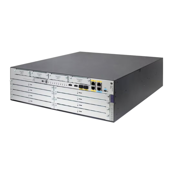
Page 70: Msr3064
MSR3064 Figure 92 MSR3064 front view (1) SIC slot (slot 4) (2)SIC slot (slot 3) (3) SIC slot (slot 2) (4) USB port 0 (5) USB port 1 (6) SIC slot (slot 1) (7) Gigabit Ethernet port (GE1) (8) Gigabit Ethernet port (GE2) (9) USB console port (CON) (10) HMIM slot (slot 5) (11) HMIM slot (slot 7) -
Page 71: Ac Power Supply
AC power supply Figure 94 AC power supply (1) Captive screw (2) Power switch (3) Air outlet vent (4) Power receptacle DC power supply Figure 95 DC power supply (1) Captive screw (2) Power switch (3) Air outlet vent (4) Power receptacle... -
Page 72: Poe Power Supply
PoE power supply Figure 96 PoE power supply (1) Captive screw (2) Power switch (3) Air outlet vent (4) Power receptacle Technical specifications Table 7 Technical specifications Item 3012 3024 3044 3064 CON/AUX ports USB console ports USB ports Gigabit Ethernet ports SIC/DSIC slots 2 SIC slots... - Page 73 Item 3012 3024 3044 3064 AC power supply Rated voltage range: 100 VAC to 240 VAC @ 50 Hz/60 Hz DC power supply Rated voltage range: –48 VDC to –60 VDC Rated power for AC/DC power 125 W 125 W AC: 300 W AC: 300 W supply...
-
Page 74: Appendix B Leds
Appendix B LEDs Panel LEDs MSR3012 Figure 97 MSR3012 LEDs (1) Console port LED (2) USB console port LED (3) SFP port LED (SFP0) (4) Gigabit Ethernet port LED (GE0) (5) Gigabit Ethernet port LED (6) Gigabit Ethernet port LED (GE1) (GE2) (7) System LED (SYS) -
Page 75: Msr3044
MSR3044 Figure 99 MSR3044 LEDs (1) CF card LED (2) System LED (SYS) (3) Power supply LED (PWR) (4) PoE power supply LED (5) VPM (slot 0) LED (VPM0) (6) VPM (slot 1) LED (VPM1) (7) Gigabit Ethernet port LED (8) SFP port LED (SFP0) (9) Gigabit Ethernet port LED (GE0) -
Page 76: Power Supply Leds
(10) SFP port LED (SFP1) (11) Gigabit Ethernet port LED (12) Console port LED (GE2) (13) USB console port LED Power supply LEDs Appearance Figure 101 AC power supply LEDs (1) Power input LED (2) Power output LED Figure 102 DC power supply LEDs (1) Power input LED (2) Power output LED... -
Page 77: Led Description
Figure 103 PoE power supply LEDs (1) Power input LED (2) Power output LED LED description LEDs State Description Flashing green (8 Hz) The BootWare runs. Steady green The SDRAM is performing self-test. Comware has started with the configuration file and the router Flashing green (1 Hz) has booted up. - Page 78 LEDs State Description The router is not using the console port. Steady green A 1000 Mbps link is present. Flashing green Data is being received or transmitted at 1000 Mbps. Steady yellow A 10/100 Mbps link is present. Flashing yellow Data is being received or transmitted at 10/100 Mbps.
-
Page 79: Appendix C Slot Arrangement
Appendix C Slot arrangement Each of the MSR3000 routers provides slots for SIC and HMIM interface cards. On the MSR3024, MSR3044, and MSR3064, you can combine two SIC slots into one DSIC slot by removing the slot divider. The fixed ports on the MSR3000 panel are located in slot 0. Table 11 Slot arrangement on the MSR3000 routers Model Slot arrangement... -
Page 80: Document Conventions And Icons
Document conventions and icons Conventions This section describes the conventions used in the documentation. Port numbering in examples The port numbers in this document are for illustration only and might be unavailable on your device. Command conventions Convention Description Bold text represents commands and keywords that you enter literally as shown. Boldface Italic text represents arguments that you replace with actual values. -
Page 81: Network Topology Icons
Network topology icons Convention Description Represents a generic network device, such as a router, switch, or firewall. Represents a routing-capable device, such as a router or Layer 3 switch. Represents a generic switch, such as a Layer 2 or Layer 3 switch, or a router that supports Layer 2 forwarding and other Layer 2 features. -
Page 82: Support And Other Resources
Hewlett Packard Enterprise Support Center More Information on Access to Support Materials page: www.hpe.com/support/AccessToSupportMaterials IMPORTANT: Access to some updates might require product entitlement when accessed through the Hewlett Packard Enterprise Support Center. You must have an HP Passport set up with relevant entitlements. -
Page 83: Websites
Websites Website Link Networking websites Hewlett Packard Enterprise Information Library for www.hpe.com/networking/resourcefinder Networking Hewlett Packard Enterprise Networking website www.hpe.com/info/networking Hewlett Packard Enterprise My Networking website www.hpe.com/networking/support Hewlett Packard Enterprise My Networking Portal www.hpe.com/networking/mynetworking Hewlett Packard Enterprise Networking Warranty www.hpe.com/networking/warranty General websites Hewlett Packard Enterprise Information Library www.hpe.com/info/enterprise/docs Hewlett Packard Enterprise Support Center... -
Page 84: Documentation Feedback
Documentation feedback Hewlett Packard Enterprise is committed to providing documentation that meets your needs. To help us improve the documentation, send any errors, suggestions, or comments to Documentation Feedback (docsfeedback@hpe.com). When submitting your feedback, include the document title, part number, edition, and publication date located on the front cover of the document. For online help content, include the product name, product version, help edition, and publication date located on the legal notices page. - Page 85 Index A C E G I L N P R S T V Network topology icons,76 Accessing Hewlett Packard Enterprise Support,77 Accessing updates,77 Panel LEDs,69 Appearance of power supplies,65 Power supply LEDs,71 Powering on the router,36 Chassis views,58 Checklist before installation,5 Replacing a CF card,48...