
Related Manuals for ABB 266FF


Summary of Contents for ABB 266FF
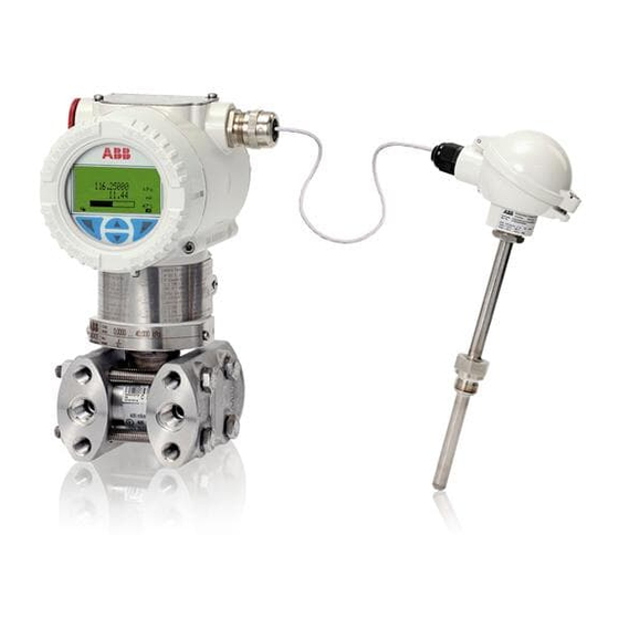
- Page 1 Operating Instruction OI/266/FF-EN Rev. B 2600T Series Pressure Transmitters 266 Models FOUNDATION Fieldbus Engineered solutions for all applications...
- Page 2 We are an established world force in the design and manufacture of measurement products for industrial process control, flow measurement, gas and liquid analysis and environmental applications. As a part of ABB, a world leader in process automation technology, we offer customers application expertise, service and support worldwide.
-
Page 3: Table Of Contents
Contents Index 5. Mounting ............. 12 1. Introduction ............5 5.1 General ..............12 1.1 Instruction manual structure ........5 5.2 IP protection & designation ........12 1.2 Models covered by this manual........5 5.3 Mounting the transmitter ......... 12 1.3 Product description ...........5 5.3.1 Transmitter factory configuration consideration . - Page 4 Contents 7. Transmitter wiring ..........30 11. Maintenance ............45 7.1 Cable connection ............ 30 11.1 Returns and removal ..........45 7.2 FOUNDATION Fieldbus wiring ........30 11.2 Pressure transmitter sensor ........45 7.3 Simple FF network and system architecture ..... 31 11.3 Removing/Installing the process flanges ....
-
Page 5: Introduction
1 Introduction 1. Introduction 1.1 Instruction manual structure The present manual provides information on installing, operating, troubleshooting the 266 pressure transmitter. Every section of the present manual is specifically dedicated to the specific phase of the transmitter lifecycle starting from the receipt of the transmitter and its identification, passing to the installation, to the electrical connections, to the configuration and to the troubleshooting and maintenance operations. -
Page 6: Safety
2.5 Use of instruction For safety reasons, ABB draws your attention to the fact that only Danger – <Serious damage to health/risk to life>. This message sufficiently insulated tools conforming to DIN EN 60900 may be indicates that an imminent risk is present. -
Page 7: Operator Liability
The device can be operated at high Warning – Risk to persons pressure and with aggressive media. Any process media released All devices sent back to ABB must be free from any hazardous may cause severe injuries. Depressurize the pipeline/tank before materials (acids, alkalis, solvents, etc.). -
Page 8: Transmitter Overview
3 Transmitter overview 3. Transmitter overview 3.1 Transmitter components overview Figure 1: Differential pressure transmitter components 1 - LCD display with keypad (L1 option) 2 - TTG display with keypad (L5 option) 3 - Standard LCD display (L9 option) Figure 2: Gauge / absolute pressure transmitter components Important. -
Page 9: Range & Span Consideration
3 Transmitter overview 3.2 Range & Span consideration The 2600T Transmitter Specification Sheets provide all information concerning the Range and Span limits in relation to the model and the sensor code. The terminology currently used to define the various parameters is as follows: URL: Upper Range Limit of a specific sensor. -
Page 10: Opening The Box
Please refer to the serial number when making enquiries to ABB service department. The same certification plate (ref.A) can be issued for ABB India Limited, 560058 Bangalore, India, with the numbers: The optional additional SST Tag plate (ref. C - code I2) also provides customer tag number and calibrated range. -
Page 11: Optional Wired-On Sst Plate (I1)
4 Opening the box 4.2 Optional wired-on SST plate (I1) The 266 transmitter can be supplied with the optional “Wired On Stainless Steel plate” (figure 4) which is permanently laser printed with a custom text specified in phase of order. The available space consists in 4 lines with 32 characters per line. -
Page 12: Mounting
ABB typically configures 266 pressure transmitters technology and safety point of view. according to the user requirements. A typical configuration... -
Page 13: Pressure Equipment Directive (Ped) (97/23/Ce)
Optional Vent/drain valves (code V1/V2/V3) on the transmitter following specifications: are located on the sensor flanges. SERIAL\NUMBER ABB S.p.A. The transmitter has to be positioned so that these drain/vent Made in Italy valves will be located higher than the taps on liquid service in... -
Page 14: Bracket Mounting (Optional)
5 Mounting 5.5.1 Bracket mounting (optional) Different mounting brackets are available please refer to the relevant installation drawing below: 29 (1.14) 18 (0.71) 58 (2.28) 55 (2.17) 18 (0.71) 91 (3.58) 66 (2.60) with plug 78 (3.07) with d/v valve 72 (2.83) 113 (4.45) 116 (4.57) - Page 15 5 Mounting 29 (1.14) 18 (0.71) 58 (2.28) 55 (2.17) 18 (0.71) 91 (3.58) 66 (2.60) with plug 78 (3.07) with d/v valve 72 (2.83) 113 (4.45) 113 (4.43) 123 (4.86) 142 (5.59) Figure 9: Differential Pressure Style transmitter with barrel housing installed on a vertical pipe with optional bracket (B2) 29 (1.14) 18 (0.71) 72 (2.83)
- Page 16 5 Mounting 29 (1.14) 18 (0.71) 116 (4.57) 87 (3.42) 136 (5.35) 183 (7.19) 55 (2.17) Figure 11: Differential Pressure Style transmitter with barrel housing and Kynar inserts installed on a horizontal pipe with optional bracket (B2) 29 (1.14) 18 (0.71) 58 (2.28) 55 (2.17) 18 (0.71) 91 (3.58)
-
Page 17: B2 Pipe And Wall Mounting Bracket Details
5 Mounting 29 (1.14) 58 (2.28) 55 (2.17) 18 (0.71) 18 (0.71) 91 (3.58) 72 (2.83) 54 (2.13) 113 (4.45) 113 (4.43) 123 (4.86) Figure 13: Differential Pressure Style transmitter with barrel housing and Kynar inserts installed on a vertical pipe with optional bracket (B2) 5.5.2 B2 Pipe and wall mounting bracket details All the bolts and nuts supplied are necessary for the installation on pipe. -
Page 18: B5 Flat Type Bracket Details
5 Mounting 29 (1.14) 18 (0.71) 18 (0.71) 58 (2.28) 55 (2.17) 91 (3.58) 95 (3.72) 70 (2.75) 174 (6.86) 142 (5.59) Figure 15: Differential Pressure Style transmitter with barrel housing installed on a box pipe with optional bracket for SST housing (B5) 5.5.3 B5 Flat type bracket details 1 –... -
Page 19: Mounting A P Style Pressure Transmitter
5 Mounting 5.6 Mounting a P style pressure transmitter If the transmitter is installed inclined with respect to the Important. (266G, 266A, 266H, 266N) vertical, the filling liquid exerts hydrostatic pressure on the The pressure transmitter can be mounted directly on the measuring diaphragm, resulting in a zero shift. - Page 20 5 Mounting 113 (4.45) 29 (1.14) 91 (3.58) 18 (0.71) 18 (0.71) 23 (0.9) width across flats of exagon Ø65 (2.56) 72 (2.83) 105 (4.12) 116 (4.57) Figure 19: Model 266H or 266N High overload resistant P-Style transmitter with sensor Z with barrel housing installed on a 2”pipe with optional bracket (B1 carbon steel or B2 Stainless Steel 316L) Attention −...
-
Page 21: B1 And B2 Barrel Housing Bracket Details
5 Mounting 5.6.1 B1 and B2 Barrel housing bracket details 1 – U-bolt 2 – U-bolt fixing washers and nuts 3 – Transmitter fixing bolts 4 – B1 or B2 bracket 5 – Fitting adapter Figure 21: Pipe and wall mounting bracket kits for P style transmitter with Barrel housing 128 (5.04) 29 (1.14) 122 (4.80) -
Page 22: B2 Din Housing Bracket Details
5 Mounting 128 (5.04) 29 (1.14) 120 (4.72) 30 (1.19) 18 (0.71) 83 (3.27) 18 (0.71) 66 (2.60) 72 (2.83) 1/2 - 14 NPT 105 (4.13) 22 (0.87) width across flats of exagon 117 (4.60) Figure 23: Model 266G or 266A P-Style transmitter with DIN housing installed on a 2”pipe with optional bracket (B2 Stainless Steel 316L) 5.6.2 B2 DIN Housing bracket details 1 –... -
Page 23: Transmitter Housing Rotation
5 Mounting 5.7 Transmitter housing rotation — Although it is not absolutely necessary to use balancing vessels with vaporous measuring media, measures must To improve field access to the wiring or the visibility of the be taken to prevent steam entering the measuring optional LCD meter, the transmitter housing may be rotated chambers of the measuring equipment (266Dx and through 360°... -
Page 24: Process Connections Considerations
5 Mounting 5.10 Process connections considerations 266 differential pressure transmitter process connections on the transmitter flange are 1/4 - 18 NPT, with a centers distance of 54mm (2.13in) between the connections. The process connections on the transmitter flange are on centers to allow direct mounting to a three-valve or five-valve manifold. -
Page 25: Installation Recommendations
5 Mounting 5.13 Installation recommendations 5.13.2 Gas or liquid (with solids in suspension) flow measurement Impulse piping configuration depends on the specific measurement application. — Place the taps to the top or side of the line. — Mount the transmitter above the taps. 5.13.1 Steam (condensable vapor) or clean liquids flow measurement The process fluid must enter the transmitter primary:... -
Page 26: Level Measurements On Closed Tanks (Dry Leg) . 26 5.13.4 Level Measurement On Closed Tanks (Wet Leg)
5 Mounting 5.13.3 Liquid level measurements on closed tanks and non condensable fluids (dry leg) — Mount the transmitter at the same height or below the lowest level to be measured. — Connect the + (H) side of the transmitter to the bottom of the tank. -
Page 27: Pressure Measurement Of A Tank
5 Mounting 5.13.6 Pressure or absolute pressure measurement of a 5.13.7 Pressure or absolute pressure measurement of a tank liquid in a pipe — Place the taps in the upper part of the tank. — Place the tap at the side of the line. —... -
Page 28: Pressure Measurement Of Vapor In A Pipe
5 Mounting 5.13.8 Pressure or absolute pressure measurement of a 5.13.9 Pressure or absolute pressure measurement of a condensable vapor in a pipe gas in a pipe — Place the tap at the side of the line. — Place the tap at the top or side of the line. —... -
Page 29: Device Introduction
Fieldbus Foundation organization website www. and stays with the device wherever it is used. fieldbus.org , from the ABB website www.abb.com/fieldbus and/or — The Control Application Process (CAP) is configured for from standards IEC 61158, IEC 61784, EN 50170/DIN 19245 and... -
Page 30: Transmitter Wiring
7 Transmitter wiring 7. Transmitter wiring 7.2 FOUNDATION Fieldbus wiring Warning - General risk. Observe the applicable regulations The 2600T-266 PdP FF is a Bus Powered device with Fieldbus governing electrical installation. Connections must only be Foundation output. The two wires of the bus have to be established in a dead-voltage state. -
Page 31: Simple Ff Network And System Architecture
7 Transmitter wiring 7.3 Simple FF network and system architecture - Operating station - Engineering station - Controller - Ethernet TCP/IP - FF-HSE - FF-H1 - Linking Device - Power Supply PwC - Power Conditioner - Termination Figure 37: FOUNDATION Fieldbus architecture 7.4 Wiring procedure —... -
Page 32: Grounding
— The GROUND and SHIELD connections must be evaluated depending by the installation rules If necessary the ground terminal could be also connected. For details about the installation and connections refers to specific documents in the Fieldbus Foundation website www.fieldbus.org and in the ABB website www.abb.com Internal ground termination point 7/8”... -
Page 33: Electronics
8 Electronics 8. Electronics 8.3 Factory default configuration 8.1 Fault protection The on-board switches are set by default in OFF position (0). The 266 PdP electronic implements the circuitry for the fault Therefore: current protection. Whenever a fatal failure occurs and the current consumption increase over the 20 mA, this circuitry SW 1 –... -
Page 34: Local Pushbuttons
9 Local pushbuttons 9. Local pushbuttons 9.2 Operations Three push buttons Zero (Z), Span (S) and Write Protection (small Lock icon) are located under the identification nameplate, The Z and S buttons are enabled by default but can be disabled as shown by the figure. -
Page 35: Wet Ranging Operation - Sw 3 = 1
— PTRB_BIAS_VALUE = 0.0 — PTRB_PRIMARY_VALUE = PTRB_CAL_VALUE Important. Should you need more details about the above mentioned FF commands, please refer to the addendum of this manual, downloadable from ABB website www.abb.com/pressure 2600T Series Pressure transmitters | OI/266/FF-EN Rev. B 35... -
Page 36: Hmi Local Indicator
10 HMI local indicator 10. HMI local indicator The 266 PdP is available with the integral HMI LCD local indicator with 4 buttons keypad as optionally item connected on the communication board. There are two types of available HMI: 10.1 Conventional version (L1 option) Gain access to the display by unscrewing the windowed cover. -
Page 37: Lcd Structure
10 HMI local indicator 10.6 LCD structure Important. It is recommended to use the Auto-scrolling only with The Device TAG and Node Address are always visible in the HMI_MODE set to One Line.. top side of the LCD. The line/s and bar-graph view depends by the HMI_MODE Selection 10.8 HMI as Diagnostic Indicator The displayed variables are identified by a max of the three... -
Page 38: Detailed Diagnostic Info From Hmi
10 HMI local indicator 10.11 HMI as configuration tool 10.8.1 Detailed diagnostic info from HMI When the above kind of diagnostic information is displayed, The HMI can be used to read and change the display from the HMI it is also possible to see the details. configuration through a dedicated menu accessible by using the 4 HMI buttons. -
Page 39: Hmi Menu Structure
10 HMI local indicator The keys (1), (4), (2) and (3) are available for the menu-controlled configuration. — The menu/submenu name is displayed above in the LCD display. — The number/line of the currently selected menu item is displayed in the upper right of the LCD display. —... - Page 40 10 HMI local indicator Display 40 OI/266/FF-EN Rev. B | 2600T Series Pressure transmitters...
- Page 41 10 HMI local indicator 2600T Series Pressure transmitters | OI/266/FF-EN Rev. B 41...
- Page 42 10 HMI local indicator 42 OI/266/FF-EN Rev. B | 2600T Series Pressure transmitters...
- Page 43 10 HMI local indicator Device Info 2600T Series Pressure transmitters | OI/266/FF-EN Rev. B 43...
- Page 44 10 HMI local indicator Communication 44 OI/266/FF-EN Rev. B | 2600T Series Pressure transmitters...
-
Page 45: Maintenance
The use of non original spare parts makes the warranty void. operating conditions), as described in the instructions in the In case you want ABB to perform the repair, please send back section “Operation resp. Configuration of the transmitter”. If... -
Page 46: Pressure Transducer Replacement
11 Maintenance – Respect the below table indications for reinstalling the process flanges. Transmitter model and range Procedure Viton Gaskets All bolting Use a torque wrench to tighten the bolts to a torque of 25 Nm. Carbon Steel NACE Use a torque wrench to tighten the process flange nuts to a torque of 40 Nm, let the flange 266DSH / PSH / VSH and Stainless Steel stabilize for an hour, unscrew the nuts and tighten again to 25 Nm. -
Page 47: Hazardous Area Considerations
12 Hazardous area considerations 12. Hazardous Area considerations Certificate IECEx Ex ia IIC T4/T5/T6 and Ex iaD 20 T85°C 12.1 Ex Safety aspects and IP Protection (Europe) FISCO, IP67 According to ATEX Directive (European Directive 94/9/EC of 23 March 1994) and relative European Standards which can IECEx certificate number assure compliance with Essential Safety Requirements, i.e., IECEx FME 09.0003X (Lenno and Minden products) - Page 48 12 Hazardous area considerations b) Certificate ATEX II 1/2 G Ex ia IIC T4/T5/T6 and Certificate IECEx Ex ia IIC T4/T5/T6 and Ex iaD 21 T85°C, FISCO, IP67 II 1/2 D Ex iaD 21 T85°C IECEx certificate number FM Approvals certificate number IECEx FME 09.0003X (Lenno and Minden products) FM09ATEX0024X (Lenno products) IECEx FMG 11.0019X (Shanghai products)
- Page 49 12 Hazardous area considerations c) Certificate ATEX II 1/2 G Ex d IIC T6 Certificate IECEx Ex d IIC T6, Ex tD A21 T85°C, Ta= -50°C to +75°C ATEX II 1/2 D Ex tD A21 IP67 T85°C (-50°C ≤ Ta ≤+75°C) IECEx certificate number FM Approvals Certificate number IECEx FME 09.0002X (Lenno and Minden products)
- Page 50 12 Hazardous area considerations According to ATEX Directive (European Directive 94/9/EC of 23 Important. It is the technical support for the ABB Declaration of March 1994) and relative Standards which can assure compliance Conformity with Essential Safety Requirements, i.e., EN 60079-0 (General requirements) EN 60079-15 (Specification for electrical apparatus with type of protection “n”) EN 61241-0 (General requirements),...
-
Page 51: Entities For "L5" Option
12 Hazardous area considerations 12.1.1 Entities for “L5” option 12.2.2 Classifications The 2600T Series pressure transmitters have been certified by (display with TTG technology) FM Approvals for the following Class, Divisions and Gas HART Version with “L5” option (display TTG) groups, hazardous classified locations, temperature class and Ui= 30Vdc Ci= 5nF... -
Page 52: Trouble Sheet
Shipping information for the return of the equipment Material returned for factory repair should be sent to the nearest ABB Service Center; transportation charges prepaid by the Purchaser Please enclose this sheet duty completed to cover letter and packing list... -
Page 53: Return Report
Signed Name Position Date ABB S.p.A Process Automation Division Uffici Commerciali / Sales Office: Via Statale, 113 - 22016 Lenno (CO) Italy Tel. +39 0344 58 111 Fax +39 0344 56 278 e-mail: abb.instrumentation@it.abb.com... -
Page 54: Ec Declaration Of Conformity
54 OI/266/FF-EN Rev. B | 2600T Series Pressure transmitters... - Page 55 2600T Series Pressure transmitters | OI/266/FF-EN Rev. B 55...
- Page 56 With regard to purchase orders, the agreed For more product information visit: particulars shall prevail. ABB does not accept any www.abb.com responsibility whatsoever for potential errors or possible lack of information in this document.