Siemens Scalance X204-2 Multimode Installation Instructions Manual
Ethernet fiber switch
Hide thumbs
Also See for Scalance X204-2 Multimode:
- Operating instructions manual (87 pages) ,
- Compact operating instructions (110 pages)
Table of Contents
Advertisement
Installation Instructions
Model Scalance X204-2 Multimode and X204-2LD Single Mode
Ethernet Fiber Switch
Fiber Switch Ethernet Connections
INTRODUCTION
INSTALLATION
Mounting on VNT-MP
VNT-MP
VNT-PS
VNT
FIBER
SWITCH
XND
Figure 2
Fiber Switch Mounting on VNT-MP
P/N 315-050537-3
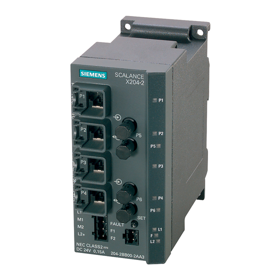
The Model Scalance X204-2 Multimode and X204--2LD Single
Mode Ethernet Fiber Switch (as shown in Figure 1) from
Siemens Building Technologies, Inc. is used to maintain a Style
7 ring or Style 4 (Class B) wiring for communications between
all buildings and Siemens Building Management Systems (Fire
Command Centers within a FVNET campus, NCC, Desigo CC,
Cerberus DMS). Both Style 7 and Style 4 perform all required
monitoring of the health of the network. Style 7 wiring will
automatically 'heal' the ring when a break or other failure is
encountered. The failure is reported via SNMP (Simple
Network Management Protocol).
The fiber switch obtains its power from a 24V UL Listed for
Fire Application, Power Limited - Regulated Power Supply. It
provides connectors for the fiber cable and four RJ45
100BaseT network connections.
In Style 7 , the fiber switch that is connected to the primary
NCC is designated as the ring master. There is no difference
in installation, configuration, and operation of single mode or
multimode fiber optic switches except the type of fiber used.
Remove all system power before installation, first battery then AC. (To power up,
connect the AC first, then the battery.)
The fiber switch mounts on a bracket in the lower left corner of the VNT-MP mount-
ing plate as shown in Figure 2. To mount the fiber switch on the bracket, place the
bottom edge of the fiber switch cutout on the bottom edge of the rail between the
VNT-MP and the standoff and then snap the top edge of the fiber switch cutout on to
the top edge of the rail. Refer to Figure 3 for the mounting detail.
RAIL FOR
MOUNTING
FIBER SWITCH
STANDOFF
TO KEEP
SWITCH
IN PLACE
Figure 3
Fiber Switch Mounting Detail
BRACKET FOR
MOUNTING
FIBER SWITCH
FIBER
Building
Building
Building T T T T T ec
Building
Building
P1
IN
P2
P5
OUT
OUT
P3
IN
P4
P6
OUT
L1+
M1
FAULT
M2
F1
L2+
L2+
F2
Figure 1
Scalance X204-2/
X204-2LD Ethernet
Multimode
Fiber Switch
1. PLACE BOTTOM EDGE OF
FIBER SWITCH GROOVE ON
BOTTOM EDGE OF RAIL.
2. SNAP TOP EDGE OF
FIBER SWITCH GROOVE
ON TO TOP EDGE OF RAIL.
Siemens
Siemens
Industry, , , , , Inc.
Industry
Industry
Inc.
Inc.
Siemens Industry
Siemens
Siemens
Industry
Inc.
Inc.
echnologies Di
ec
ec
ec
hnologies Di
hnologies Di
hnologies Division
hnologies Di
vision
vision
vision
vision
Advertisement
Table of Contents

Related Manuals for Siemens Scalance X204-2 Multimode


Summary of Contents for Siemens Scalance X204-2 Multimode
-
Page 1: Installation Instructions
The Model Scalance X204-2 Multimode and X204--2LD Single Mode Ethernet Fiber Switch (as shown in Figure 1) from Siemens Building Technologies, Inc. is used to maintain a Style 7 ring or Style 4 (Class B) wiring for communications between all buildings and Siemens Building Management Systems (Fire Command Centers within a FVNET campus, NCC, Desigo CC, Cerberus DMS). - Page 2 Figure 7 shows the wiring of the fiber switch in a VNT-FCC (Fire Command Center) configuration. Refer to Figures 10 and 11 for the wiring of the fiber switch to PAD-3 and PAD-4 and Siemens Building Management System. Fiber Connections Two fiber optic cables are required between each pair of fiber switch modules.
- Page 3 CONNECTING TO VNT-BUILDING Siemens Industry, Inc. P/N 315-050537-3 Building Technologies Division...
- Page 4 CONNECTING TO VNT-FCC (FIRE COMMAND CENTER) Siemens Industry, Inc. P/N 315-050537-3 Building Technologies Division...
- Page 5 AC first and then the battery.) Figures 8 and 9 show the general layout of the PAD-3 and PAD-4 main board, respectively. This section also provides specific wiring details to the Siemens UL approved power supply. Consult your control unit manual for specific wiring information on the control unit being used.
- Page 6 (60-180 minutes) if AC is low or lost. Note: The N.C. contact is the relay contact that is closed when the PAD-4 has power and there are no trouble conditions. Siemens Industry, Inc. P/N 315-050537-3 Building Technologies Division...
- Page 7 Siemens Building Management System Figure 10 Scalance X204-2 Multimode or X204-2LD Single Mode Ethernet Fiber Switch Connection to PAD-3 TB11 TB12 TB13 TB14 1+ 1- NC COM NO NAC1B NAC2B (NAC1A) INPUT 1 INPUT 2 Siemens Building Management System Figure 11 Scalance X204-2 Multimode or X204-2LD Single Mode Ethernet Fiber Switch Connection to PAD-4 Siemens Industry, Inc.
- Page 8 CONFIGURING THE SCALANCE X204-2 MULTIMODE OR X204-2LD SINGLE MODE ETHERNET FIBER SWITCH This section describes how to assign an IP address to the Scalance X204-2 Multi- mode or X204-2LD Single Mode Ethernet Fiber Switch and the methods used for determining IP addresses to assign to the switches. It also describes how to config- ure one of the switches as the ring master.
- Page 9 To check that these protocols are installed, click Start->Network Connec- tions->Local Area Connection. Figure 13 Checking Local Area Connection • Verify that the DLC Protokoll and Profinet IO RT-Protocol are installed. Figure 14 Verify Local Area Connection Items Siemens Industry, Inc. P/N 315-050537-3 Building Technologies Division...
- Page 10 Choose “Use the following IP address” and pick an address in the same network as the fiber switch. Use a subnet mask of 255.255.255.0. Figure 16 Changing the IP Address of the Laptop/PC Siemens Industry, Inc. P/N 315-050537-3 Building Technologies Division...
- Page 11 Select the “Assign IP Parameters” option button and enter the IP address for the device in the IP address box. • In the Subnet mask box enter 255.255.255.0 as the Subnet mask. Figure 18 Figure 18a Enter Primary Setup Tool Data Siemens Industry, Inc. P/N 315-050537-3 Building Technologies Division...
- Page 12 Type “admin” as user ID and “admin” as password. (The user is advised to change the password.) Select the X204-2 icon if connected to multimode or the X204-2LD icon if connected to single mode fiber optic switch. Siemens Industry, Inc. P/N 315-050537-3 Building Technologies Division...
- Page 13 Difference in connection between Single Mode X204-2LD and Multimode There is only notification of identity of the scalance switch of single or multimode on the window title. There are no differences in configuration, operation, or statust diagnostics. Siemens Industry, Inc. P/N 315-050537-3 Building Technologies Division...
- Page 14 Select the redundancy mode as either HRP Redundancy Manager or HRP Redundancy Client. Redundancy Manager should be selected for only one switch in the network. Figure 20 Ring Redundancy Manager Configuration Figure 20a Siemens Industry, Inc. P/N 315-050537-3 Building Technologies Division...
- Page 15 Simple Network Management Protocol (SNMP). Web Based Manage- ment (WBM) is the tool used for these settings. Figure 22 Fault Mask Siemens Industry, Inc. P/N 315-050537-3 Building Technologies Division...
- Page 16 If PAD-3 or PAD-4 is used, then Redundant power supply must be checked at Fault Mask and should be wired to M2 L2 on the switch. Power Line 1 and Power Line 2 should be checked for monitoring. Siemens Industry, Inc. P/N 315-050537-3 Building Technologies Division...
- Page 17 Select the following Agent Enabled Features: SNMP Traps TELNET (Optional) Confirm that the IP address is the same as the switch IP address. Click on the “Set Values” button. Figure 24 Agent Configuration Siemens Industry, Inc. P/N 315-050537-3 Building Technologies Division...
- Page 18 Click on the “Set Values” button. Figure 25 Agent Event Configuration The settings shown in Figure 23 are the only permitted settings for UL 864. Siemens Industry, Inc. P/N 315-050537-3 Building Technologies Division...
- Page 19 In the second IP Address field enter the NCC IP address for the SCC (Secondary Command Center). Check Enable trap for the second item. Click on the “Set Values” button. Figure 26 Agent Trap Configuration Siemens Industry, Inc. P/N 315-050537-3 Building Technologies Division...
- Page 20 System Version Numbers To get to the following dialog box, click on system, then Version Numbers. Figure 27 System Version Numbers: Multimode Fiber Optic System Version Figure 27a: Single Mode Fiber Optic System Version Siemens Industry, Inc. P/N 315-050537-3 Building Technologies Division...
- Page 21 PC to the Scalance fiber switch. You can also load new firmware from a file located on your client PC. You can make the entries required for this on the page of the System Save & Load HTTP menu. Figure 28 System Save & Load Via HTTP Siemens Industry, Inc. P/N 315-050537-3 Building Technologies Division...
- Page 22 Red indicates an error. Green LEDs indicate that the switch is running properly. Green also indicates ports that have an Ethernet connection to them. Figure 29 Fiber Switch Diagnostic Indicators Siemens Industry, Inc. P/N 315-050537-3 Building Technologies Division...
- Page 23 From Internet Protocol Properties window choose Use the following IP address and choose and IP address in the range 192.168.1.60 - 192.168.1.63 with the subnet mask of 255.255.255.0. Figure 30 IP Address Setup Siemens Industry, Inc. P/N 315-050537-3 Building Technologies Division...
- Page 24 Simple Network Management Protocol and click OK. From the Windows Components Wizard window click Next and follow instructions until installation is complete. Figure 32 SNMP Protocol Setup - Management and Monitoring Tools Siemens Industry, Inc. P/N 315-050537-3 Building Technologies Division...
- Page 25 This is a list of all XLS/MXL nodes and NCCs in an entire complex that are communicating with the NCC. • To add a new NCC, XLS or MXL Node into the NCC, click the Add button. Siemens Industry, Inc. P/N 315-050537-3 Building Technologies Division...
- Page 26 Choose the Type of NCC-G Node as either “This Unit” or “Remote Unit. ” • Type the TCP/IP Network Address as the IP address of the NCC PC. • Click the Save button. Siemens Industry, Inc. P/N 315-050537-3 Building Technologies Division...
- Page 27 • Add a Node Name. • Choose “XLS” as the Node Type. • Choose the Node numbers of the NCC as the Default NCC-G Control Setting. • Click the Save button. Siemens Industry, Inc. P/N 315-050537-3 Building Technologies Division...
- Page 28 Multimode Fiber Switch as shown in Figure 37 . Click on “Fiber Optic Switch” button to open the Fiber Optic Switch List window to add, delete or update a Fiber Optic Switch. Siemens Industry, Inc. P/N 315-050537-3 Building Technologies Division...
- Page 29 Delete A Switch To delete a Fiber Optic Switch, complete the following steps: Select the switch you want to delete from the Fiber Optic Switch List window. Click on the Delete button. Siemens Industry, Inc. P/N 315-050537-3 Building Technologies Division...
- Page 30 You can update the IP address and /or the Ring Redundant Manager setting. Click on the update button to complete the changes or on Cancel to leave the settings as they were. Figure 40 Updating A Fiber Optic Switch Siemens Industry, Inc. P/N 315-050537-3 Building Technologies Division...
- Page 31 Cyber security disclaimer Siemens products and solutions provide security functions to ensure the secure operation of building comfort, fire safety, security management and physical security systems. The security functions on these products and solutions are important components of a comprehensive security concept.
- Page 32 THIS PAGE HAS BEEN LEFT INTENTIONALLY BLANK Siemens Industry, Inc. Siemens Canada, Ltd. Doc No. A5Q00064184A-02 P/N 315-050537-3 Building Technologies Division 1577 North Service Road East Document ID A6V10320072 Florham Park, NJ Oakville, Ontario L6H 0H6 Canada...