
Related Manuals for ABB PSE 18


Summary of Contents for ABB PSE 18
- Page 1 Softstarters Type PSE18...PSE370 Installation and commissioning manual 0 0 -7 1 8 -6 P S E 0 0 -7 1 8 -6 P S E 0 0 -7 1 8 -6 P S E...
- Page 2 This manual belongs to: __________________________________________ Softstarters Type PSE18...PSE370 Installation and commissioning manual 1SFC132057M0201...
- Page 3 Installation and Commissioning Manual ABB Softstarters PSE18...PSE370 1 General This is the Installation and Commissioning Manual for Softstarters Type PSE18… PSE370 based on software version 01.01.02. Document number: 1SFC132057M0201 Revision: E Issue date: 2011-01-25 Data subject to change without notice.
- Page 4 2 Safety This chapter describes warning and information signs used in this manual, which the user should pay attention to. The softstarter shall be installed by authorized personnel only. This manual is a part of the PSE Softstarter and should always be accessible to personnel working with this product.
-
Page 5: Table Of Contents
Chapter Introduction ..........Quickstart ..........Description ..........Mounting ..........Connection ..........Human-Machine Interface (HMI) ....Functions and configuration ....Fieldbus communication ......Maintenance ........... Troubleshooting ........Wiring diagrams ........Index ............Customer feedback report ....... 102 Softstarters Type PSE18...PSE370 Installation and commissioning manual 1SFC132057M0201... -
Page 6: Softstarters Type Pse18...Pse370 Installation And Commissioning Manual 1Sfc132057M0201
Notes Softstarters Type PSE18...PSE370 Installation and commissioning manual 1SFC132057M0201... - Page 7 Chapter 1 Introduction Documentation for PSE18...PSE370 softstarter .......... Installation and Commissioning ..............Intended audience ................. General ..................... Requirements ..................Revision notes and other documents ............. Acronyms and abbreviations ..............Explanation of concepts ................. Softstarters Type PSE18...PSE370 Installation and commissioning manual 1SFC132057M0201 Chapter 1...
-
Page 8: Documentation For Pse18
ID 1SFC132059M9901. For quickest possible start, read Chapter 2 Quickstart or go to the short form manual (1SFC132059M9901). A complete compilation of ABB’s softstarters can be found in Main catalogue Softstarters, document ID 1SFC132005C0201. Chapter 1 Softstarters Type PSE18...PSE370 Installation and commissioning manual 1SFC132057M0201... -
Page 9: Intended Audience
1.2.2 Revision notes and other documents For latest information on revisions and other documents related to the PSE Softstarters, please check www.abb.com/lowvoltage/. On this site select the link Control Products and then continue to Softstarters. Softstarters Type PSE18...PSE370 Installation and commissioning manual 1SFC132057M0201... -
Page 10: Acronyms And Abbreviations
1.2.3 Acronyms and abbreviations The acronyms and abbreviations described in table 1.1 are used in this manual. Table 1.1 Acronym/ abbre- Description viation By-pass Direct-on-line Electronic overload protection for the Motor Fieldbus FieldBusPlug Human-Machine Interface Rated operational current Information Technology Liquid Crystal Display Light Emitting Diode Printed Circuit Board... - Page 11 Chapter 2 Quickstart Quickstart ....................Softstarters Type PSE18...PSE370 Installation and commissioning manual 1SFC132057M0201 Chapter 2...
-
Page 12: Quickstart
Chapter 2 Quickstart This chapter is a short guide on how to connect, configure and start the softstarter in the easiest way. This product has been carefully manufactured and tested but there is a risk that damage can occur from abnormal handling during transportation. Therefore, the procedure below should be followed during initial installation: Ready Protection... - Page 13 Connect control supply voltage to terminals 1 and 2 (100-250 V 50/60 Hz). Connect the functional earth to terminal 14, with an earthing point close to Exit Select Reset the softstarter. Exit Select Reset Exit Select Reset The earthing is not a protective earth, it is a functional earth. The earthing cable should be as short as possible.
- Page 14 This page is intentionally left blank. Chapter 2 Softstarters Type PSE18...PSE370 Installation and commissioning manual 1SFC132057M0201...
- Page 15 Chapter 3 Description Overview ....................Markings and connections ................Type designation ..................Documentation ................... Environmental influence ................Specifications ..................... Technical data .................... General ....................Weights ....................PSE Softstarter types ................IEC information ..................information ................Dimensions .................... Drilling plan .................... Softstarters Type PSE18...PSE370 Installation and commissioning manual 1SFC132057M0201 Chapter 3...
-
Page 16: Overview
Chapter 3 Description This chapter describes the PSE Softstarter in general, specifications as well as available accessories and spare parts. 3.1 Overview The PSE Softstarter is a microprocessor-based softstarter designed with the latest technology for soft starting and soft stopping of three-phase squirrel cage motors. The softstarter has several advanced features as standard. -
Page 17: Markings And Connections
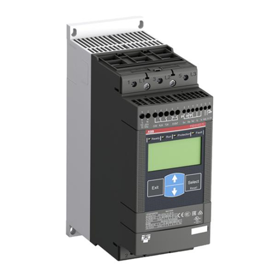
3.2 Markings and connections Line side connection Supply voltage U Terminal marking of 9 10 11 12 13 14 control circuits PSE 18-600-70 Green Green Display Yellow Keypad Order code Technical data according Fieldbus connection to IEC 947-4-2 Technical data according to UL 508 and CSA-C22.2 No. -
Page 18: Type Designation
Figure 3.4: Type designation 3.4 Documentation Documentation such as brochures, catalogs, certificates, and drawings included can be found at: www.abb.com/lowvoltage. Select the link Control Products and then continue to Softstarters. 3.5 Environmental influence The product is designed to minimize the environmental effects during manufactur- ing and use of the product. -
Page 19: Technical Data
3.7 Technical data 3.7.1 General Table 3.2 General data Rated insulation voltage, U i 600 V Rated operational voltage, U e 208-600 V 50 / 60 Hz Rated control supply voltage, U s 100 - 250 V 50 / 60 Hz Voltage tolerance +10% to -15% Frequency tolerance... -
Page 20: Pse Softstarter Types
3.7.3 PSE Softstarter types Table 3.4 Type PSE 18 PSE 25 PSE 30 PSE 37 Rated Current I e (A) Motor size 380 - 415 V (kW) 18.5 Motor size 480 V (hp) Motor size 600 V (hp) Power loss at Rated Current (W) -
Page 21: Iec Information
3.7.4 IEC information Equipment suitable for use in a circuit with maximum available fault current as shown when protected by devices indicated in table 3.8. Examples of semicon- ductor fuses and MCCB according to IEC. For more information about fuses see: http://www.abbcontrol.fr/coordination_tables/coordtable.htm Table 3.8 Type 2 co-ordination... -
Page 22: Information
3.7.5 information Examples of equipment suitable for use in a circuit with maximum available fault current as shown when protected by devices indicated. See table 3.9. For more information see: http://www.abbcontrol.fr/coordination_tables/coordtable.htm Table 3.9 Fuses MCCB MCCB Normal breaker Standard breaker 550-600V 440-480V 550-600V... -
Page 23: Dimensions
3.7.6 Dimensions Dimensions PSE 18...105 6,5 mm (0.256 in) PSE 18-600-70 13 mm (0.512 in) 30 mm (1.181 in) 80 mm (3.150 in) 90 mm (3.543 in) Dimensions PSE 142...170 6,5 mm (0.256 in) PSE142-600-70 35 mm (1.378 in) 17,5 mm (0.689 in) 113,5 mm (4.468 in) - Page 24 Dimensions PSE 210...370 6,5 mm (0.256 in) PSE210-600-70 43,75 mm 19,6 mm (1.723 in) (0.772 in) 190 mm (7.480 in) 163,5 mm (6.437 in) Chapter 3 Softstarters Type PSE18...PSE370 Installation and commissioning manual 1SFC132057M0201...
-
Page 25: Drilling Plan
3.7.7 Drilling plan Drilling plan PSE 18...105 Drilling plan PSE142...170 1 / 4 i n M 6 ( 1 1 3 , 5 8 i n ) ( 4 . 4 6 i n ) 0 . 9 4 5... - Page 26 Drilling plan PSE210...370 1 / 4 i n M 6 ( 1 6 3 , 5 7 i n ) ( 6 . 4 3 -7 0 -6 0 0 2 1 0 P S E i n ) 0 . 9 4 4 m ( 2 5 3 2 m Chapter 3...
- Page 27 Chapter 4 Mounting Receiving, unpacking and checking ............Intermediate storage ................Mounting ....................Handling when mounting ............... Requirements ..................Minimum enclosure size ................. Minimum distance to wall and front ............Softstarters Type PSE18...PSE370 Installation and commissioning manual 1SFC132057M0201 Chapter 4...
-
Page 28: Receiving, Unpacking And Checking
Chapter 4 Mounting This chapter describes instructions on how to receive the softstarter and how to mount it in a proper way. 4.1 Receiving, unpacking and checking • Check that the package is turned with the correct side up, figures 4.1 and 4.2. • Check for transport damages. • Remove the transport casing. •... -
Page 29: Requirements
4.2.2 Requirements See Chapter 3 Description for environmental requirements. The PSE Softstarters exist in three different physical sizes which are designed to be mounted with M6 (1/4 in.) bolts as well as bolts of equivalent dimension and strength. Measures and drilling plans will be found in chapters 3.7.6 Dimensions and 3.7.7 Drilling plan. -
Page 30: Minimum Distance To Wall And Front
[inch]) PSE18...105 [3.94] [0.394] [0.788] PSE142...170 [3.94] [0.394] [0.788] PSE210...370 [3.94] [0.394] [0.788] PSE 18-600-70 PSE 18-600-70 Figure 4.5: Minimum distances to wall and front Figure 4.6: Maximum mounting angle Chapter 4 Softstarters Type PSE18...PSE370 Installation and commissioning manual 1SFC132057M0201... - Page 31 Chapter 5 Connection General ....................... Electrical connection ................... Considerations when controlling two of three phases ......Before connecting softstarters PSE18...PSE170 ........Connection of the operational power circuit ........... Control supply and control circuit ............Control supply voltage, terminals 1 and 2 .......... Functional earth, terminal 14 ..............
-
Page 32: General
Chapter 5 Connection This chapter describes the electrical connections as well as connections for com- munication devices that have to be made before you can use the softstarter. 5.1 General Caution! Mounting and electrical connection of the softstarter shall be made in ac- cordance with existing laws and regulations and be performed by autho- rized personnel. -
Page 33: Before Connecting Softstarters Pse18
Chapter 11. Caution! Softstarters PSE18...PSE370 must not be connected Inside Delta since this Figure 5.2: ABB PSE Softstarter must be con- will cause damage to the equipment and there is a risk of death or serious nected In Line only. -
Page 34: Connection Of The Operational Power Circuit
5.2.3 Connection of the operational power circuit The softstarter is recommended to be connected with a line contactor as de- scribed in figure 5.1. Additional circuit diagrams will be found in Chapter 11 Wiring diagrams. Softstarters PSE18...PSE105 are provided with built-in cable clamps. The cables must be stripped before connection, and the length of the exposed wire should be 20 mm or 0.8 in. -
Page 35: Control Supply And Control Circuit
5.2.4 Control supply and control circuit Wires in industrial control applications are divided into three groups: main power supply, control supply and control. 5.2.4.1 Control supply voltage, terminals 1 and 2 Connect neutral and live to terminal 1 and 2, as shown in figures 5.6 and 5.7. Check that you have the correct control supply voltage U s . -
Page 36: Functional Earth, Terminal 14
5.2.4.2 Functional earth, terminal 14 Connect the cable to an earthing point close to the softstarter. The cable should be as short as possible. A suitable earthing point would be next to the softstarter on the mounting plate, as shown in figures 5.8 and 5.9. The mounting plate should also be earthed. -
Page 37: Start And Stop, Terminals 8 And 9 In Circuit With Terminals 11 Or 12
Start Start Stop 9 10 11 12 13 14 9 10 11 12 13 14 PSE 18-600-70 PSE 18-600-70 Figure 5.10: Terminals for start and stop, conventional Figure 5.11: Terminals for start and stop, conventional circuit with push button circuit with auxiliary relay 3,5 x 0,6 mm AWG 24 ... -
Page 38: Reset Event, Terminal 10
11, 12 and 13. Failure to observe the above may damage the softstarter and the warranty may no longer be valid. Reset 9 10 11 12 13 14 PSE 18-600-70 Figure 5.13: Terminal for reset event 3,5 x 0,6 mm AWG 24 ... 12 8 9 10 11 12 13 (0.138 x 0.024 in) -
Page 39: Analog Output, Terminals 13 And 14
11, 12 and 13. Failure to observe the above may damage the softstarter and the warranty may no longer be valid. 9 10 11 12 13 14 PSE 18-600-70 Figure 5.15: Terminals for analog output 3,5 x 0,6 mm AWG 24 ... 12 8 9 10 11 12 13 (0.138 x 0.024 in) -
Page 40: Status Output Relays, Terminals 3, 4, 5, 6, And 7
3, 4, 5, 6 and 7. Failure to observe the above may damage the softstarter and the warranty may no longer be valid. 9 10 11 12 13 14 PSE 18-600-70 Figure 5.17: Terminals for status output signals 4 x 0,8 mm AWG 24 ... -
Page 41: Connection Of Communication Devices (Optional)
5.3 Connection of communication devices (optional) 5.3.1 External keypad An external keypad for door mounting can be connected to the softstarter. A 3-meter cable including both the communication and the power supply to the keypad makes the connection. The cable shall be connected to the external key- pad connection at the bottom of the softstarter. -
Page 42: Transfer Of Parameters
5.3.1.2 Transfer of parameters To transfer (copy) parameters from one PSE Softstarter to another, connect the External keypad to the chosen softstarter and follow the sequence below. For more information about navigating, see Chapter 6 in this manual. The Transfer Parameter menu is hidden and only possible to reach when the external keypad is connected to the softstarter. -
Page 43: Fieldbus Communication
5.3.2 Fieldbus communication See Chapter 8 Fieldbus communication. Softstarters Type PSE18...PSE370 Installation and commissioning manual 1SFC132057M0201 Chapter 5... - Page 44 This page is intentionally left blank. Chapter 5 Softstarters Type PSE18...PSE370 Installation and commissioning manual 1SFC132057M0201...
- Page 45 Chapter 6 Human-Machine Interface (HMI) Overview ....................Application ..................... Design ....................LED status indicators ................. LCD display and keypad ..............Locking/unlocking the keypad ..............Reset of all settings ................Reset of tripping events ................. Menu structure ..................Information Level ................Settings Level and settings menu ............
-
Page 46: Overview
Chapter 6 Human-Machine Interface This chapter describes how the Human-Machine Interface (keypad, LED status indicators and LCD display) works. 6.1 Overview Ready Protection Fault 6.1.1 Application The Human-Machine Interface is used for several purposes such as setting up the PSE Softstarter parameters, including protection functions and fieldbus communi- cation. -
Page 47: Led Status Indicators
6.1.2.1 LED status indicators The LED status indicators work as in table 6.1: Table 6.1 Color Description Ready Green • Off: when control supply voltage U s is off or uncon- nected. • Flashing light when control supply voltage U s is On and operational voltage U e is Off. -
Page 48: Lcd Display And Keypad
6.1.2.2 LCD display and keypad The keypad is based on the same user concept as common on mobile phones. See figure 6.1. Ready Protection Fault The LCD display contains three rows. The top row has 8 parameter icons. The middle row has a lock symbol, 4 digits and units. The bottom row has 4 param- eter icons. -
Page 49: Locking/Unlocking The Keypad
Ready Protection Fault 6.1.3 Locking/unlocking the keypad 1. Press the Exit key to exit to the Information Level. 2. The keypad is unlocked if the middle row is not indicating the lock icon to the right. 3. Press both Navigation keys 4 seconds to lock the keypad, and protect all parameter settings from unintentional change from the keypad. -
Page 50: Menu Structure
6.1.6 Menu structure The structure of the menu is described in figure 6.8. All different parameters and levels of the menu, and how they can be reached by scrolling, are also described. Figure 6.5: Information Level 6.1.6.1 Information Level By pressing a key the backlight will be switched on, and the Information Level will be displayed. - Page 51 Information Level Lock/Unlock Settings Level Exit Select Reset Reset all parameter settings to user default values I e (Rated current of motor) Individual Settings level Start Ramp time OFF, 1...30 s Stop Ramp time OFF, 1...30 s Initial/End Voltage 30...70 % Current Limit 1.5...7 x I e Torque Control during start ramp...
-
Page 52: Navigating The Menu
6.2 Navigating the menu The menu is navigated by the keypad. The Navigation keys are used to scroll up or down. The Select key is used to select a setting and save. The Exit key is used to cancel without selecting or saving a setting, and to go to a higher level of the Exit Select menu, as illustrated in figure 6.9. - Page 53 Exit Select Reset Exit Select Reset Exit Select Reset Exit Select Exit Select Reset Reset Exit Select Reset Figure 6.10: Navigating the menu Softstarters Type PSE18...PSE370 Installation and commissioning manual 1SFC132057M0201 Chapter 6...
- Page 54 This page is intentionally left blank. Chapter 6 Softstarters Type PSE18...PSE370 Installation and commissioning manual 1SFC132057M0201...
- Page 55 Chapter 7 Functions and configuration Softstarter operational data ................ Parameter settings ..................List of available parameters ................ Basic settings principal ................Functions ....................Rated Current I e of motor ..............Start Ramp Time ..................Stop Ramp Time ..................Initial/End Voltage ................... Current Limit ..................
-
Page 56: Softstarter Operational Data
Chapter 7 Functions and configuration How to navigate the menu, see Chapter 6 Human-Machine Interface (HMI), espe- cially chapter 6.2 Navigating the menu. 7.1 Softstarter operational data The information level is the top level of the user menu. Information about output current, line voltage, power factor, and voltage to the motor is displayed. -
Page 57: List Of Available Parameters
7.3 List of available parameters A list of the available parameters for PSE18...PSE370 is visible in table 7.1. Table 7.1 Description Display Setting range Default Access Actual setting symbol value from Rated Current of motor I e Individual Individual See tables in chapter 3.7.3 PSE Softstarter types. - Page 58 Description Display Setting range Default Access Actual setting symbol value from Underload Protection Level Type of operation HAnd Locked Rotor Protection Level Type of operation HAnd Fieldbus Control OFF/On Fieldbus address Download Parameter dPon dPoF/dPon Fieldbus Operation When Fault LocC LocC/trIP Type of Operation HAnd...
-
Page 59: Basic Settings Principal
7.4 Basic settings principal The Settings level (menu) consists of predefined parameters for the selected application which should be used if an easy and quick set- up is required. At any point, press Exit to cancel a setting and return to the informa- tion level. -
Page 60: Functions
7.5 Functions This chapter describes all settings and functions possible in the PSE Softstarter, as well as the easiest way of finding them. Respective default values, setting ranges and parameter strings shown in the display are also stated. 7.5.1 Rated Current I e of motor This parameter allows for configuring of the current that the softstarter will be exposed to. -
Page 61: Stop Ramp Time
7.5.3 Stop Ramp Time The Stop Ramp Time parameter allows for tuning of the time for the stop ramp to reach the End Voltage from Top of Ramp (TOR). When a stop signal is given the PSE Softstarter performs a stop ramp by control- ling the output voltage to the motor so that the voltage is decreased linearly from full voltage to the end voltage level. -
Page 62: Initial/End Voltage
7.5.4 Initial/End Voltage This parameter makes it possible to set the initial voltage level where the start ramp begins. The value for end voltage where the stop ramp ends, will automati- cally be 10 percent lower than the initial voltage. During start ramp will then the voltage increase from the initial voltage level, to full voltage. -
Page 63: Current Limit
7.5.5 Current Limit It is possible to limit the starting current by using this function. The limit can not be exceeded during start and stop ramp. When the Current Limit is reached, the output voltage stays stable until the current level falls below the limit, then the ramping continues. -
Page 64: Torque Control During Start Ramp
7.5.6 Torque Control during start ramp It is possible to use the torque control during the start by activating this parameter. Torque control results in a more linear accelerating of the speed in a majority of applications. When using the torque control the output voltage to the motor is controlled so that the motor torque will follow a predefined optimal curve from the initial voltage level to full voltage during start. -
Page 65: Torque Control During Stop Ramp
7.5.7 Torque Control during stop ramp When activating this parameter (On) makes it possible to control the motor torque during stop. Using torque control will result in a more suitable decelerating of the speed mainly requested when stopping pumps. When using torque control the output voltage to the motor is controlled so that the motor torque will follow a predefined optimal curve for best possible stop. -
Page 66: Kick Start
7.5.8 Kick Start This parameter makes it possible to tune the kick start voltage level which is ap- plied for a short time duration, before a normal start ramp is performed. Kick Start provides enough torque during start, but still ensuring a soft start. It can be set on any of the predefined voltage levels. -
Page 67: Electronic Motor Overload Protection E.o.l
7.5.9 Electronic Motor Overload Protection E.O.L. This parameter makes it possible to set the required class of motor overload pro- tection. Four different classes are available. See figure 7.21. • Class 10A • Class 10 • Class 20 • Class 30 There is an option for type of reset after tripping. -
Page 68: Underload Protection
7.5.10 Underload Protection When active the Underload Protection trip if the current (I e ) will fall to a lower level than the set value for 30 seconds or more. This protection could be used to avoid for example a pump running dry, detect a broken belt or similar. -
Page 69: Locked Rotor Protection
7.5.11 Locked Rotor Protection This protection will when activated trip if the motor current exceeds the set level when the motor is running at full voltage. The Locked Rotor Protection parameter will be activated when the motor has been running at full voltage (Top of Ramp) for 30 seconds. -
Page 70: Fieldbus Control (Optional Hardware Required)
7.5.12 FieldBus Control (optional hardware required) This parameter is used for configuration of the fieldbus communication. Con- necting the PSE Softstarter to the FieldBusPlug automatically enables fieldbus communication. To enable control of the softstarter using fieldbus, this parameter must be set to On. If FieldBus Control is set to OFF, fieldbus can only be used for monitoring softstarter data. -
Page 71: Fieldbus Address
7.5.12.1 Fieldbus Address The parameter Fieldbus Address allows setting of address for the fieldbus com- munication. The setting range for the fieldbus address is 0...255. If the address is set to 255, the address stored in internal memory of the fieldbus plug will be used. See docu- mentation for the fieldbus plug for more details on address setting. -
Page 72: Fieldbus Operation When Fault
7.5.12.3 Fieldbus Operation When Fault This parameter is accessible only if Fieldbus Control is previously set to On. In case of fieldbus malfunction, for instance due to power loss or a broken cable, this parameter allows for different (operations in case of a fault) reactions to the fault. -
Page 73: Type Of Operation For Reset Of Fieldbus Fault
7.5.12.4 Type of Operation for Reset of Fieldbus Fault Select what operation shall be asserted if a fieldbus communication fault occurs. Manual or automatic options are available. HAnd is the default value for reset of Fieldbus Fault: • If HAnd is selected - The motor will stop and manual reset is required. •... -
Page 74: Special Functions
7.7 Special functions Ready Protection Fault 7.7.1 Reset all parameter settings to user default values Start from Information Level and press in sequence the keys Exit and Select for a few seconds, as described in figure 7.29. The text string “rES” will be displayed on the LCD as in figure 7.34. -
Page 75: Pse Parameter
7.7.2 PSE parameter Ready Protection Fault This parameter contains information about the type of PSE Softstarter which is available. The PSE parameter must be configured after replacing the PCB. This parameter must not be changed if the PCB has not been replaced. Read chap- ter 3.3 Type designation to get information about how to find out the size of the softstarter. -
Page 76: Representation Of Signals In Time Domain
7.8 Representation of signals in time domain Timing diagram for the basic functions of the softstarter, with a representation of a set of signals in the time domain is found in table 7.3. Table 7.3: Timing diagram 5 6 7 13 14 Control supply voltage Operational voltage on the... -
Page 77: Application Settings
7.9 Application settings In table 7.4 the recommended parameter settings for different applications are described. Table 7.4: Application settings Recommended basic setting Centrifugal fan 10 s 40 % 5.0 x I e Axial fan 10 s 40 % 5.0 x I e Centrifugal 10 s 10 s... - Page 78 This page is intentionally left blank. Chapter 7 Softstarters Type PSE18...PSE370 Installation and commissioning manual 1SFC132057M0201...
- Page 79 Chapter 8 Fieldbus communication (option) Overview ....................Required accessories ................Instructions .................... Softstarters Type PSE18...PSE370 Installation and commissioning manual 1SFC132057M0201 Chapter 8...
-
Page 80: Fieldbus Communication
Chapter 8 Fieldbus communication 8.1 Overview The PSE Softstarter has an interface on the front for connecting the ABB Field- BusPlug used for fieldbus communication. Through this interface it is possible to control the softstarter, retreive status information, as well as upload and download of parameters. - Page 81 Chapter 9 Maintenance Regular maintenance .................. Service and repair ..................Softstarters Type PSE18...PSE370 Installation and commissioning manual 1SFC132057M0201 Chapter 9...
-
Page 82: Maintenance
9.2 Service and repair In case the PSE Softstarter has to be repaired, a spare parts list and necessary instructions are available at: www.abb.com/lowvoltage. Select the link Control Products and then continue to Softstarters. •... - Page 83 Chapter 10 Troubleshooting General ....................... Overview of indications ................Tripping events ................... Start up problems and faults ............... General problems and faults ............... Fault indications ..................Protection indications ................. Failure indications ..................Softstarters Type PSE18...PSE370 Installation and commissioning manual 1SFC132057M0201 Chapter 10...
-
Page 84: General
Chapter 10 Troubleshooting 10.1 General This chapter is a guide that can be used in case problems should arise with the PSE Softstarter or the application. The PSE Softstarter normally indicates a fault with LED Fault status indicator, and the LCD displays type of fault. When a protection is activated, it will be indicated with the LED protection status indicator, and the LCD displays what type of protection is active. -
Page 85: Tripping Events
10.3 Tripping events Depending on PSE Softstarter configuration, different events may be signalled on the LCD. All event codes are found in table 10.2: Event list. Table 10.2: Event list Event Event description Cause code SF20 Software fault Fault in software By-pass relay/contactor does not open or thyristor short circuit Shunt fault SF3x... -
Page 86: Start Up Problems And Faults
10.4 Start up problems and faults Status Possible cause Solution LED’s not lighting and LCD is blank. Control supply voltage U s is not con- • Connect according to a circuit dia- nected. gram. See Chapter 5 Connection and Chapter 11 Wiring diagrams. Ready Protection Fault... -
Page 87: General Problems And Faults
See chapter 7.5.2. Incorrect Initial/End Voltage. • Try different settings for the parameter Initial /End Voltage. See chapter 7.5.4, or contact your ABB Sales Office. Incorrect current limit. • Try different settings for the parameter Current Limit. See chapter 7.5.5, or contact your ABB Sales Office. - Page 88 Status Possible cause Solution Displayed current in LCD is not stable. The motor is too small. • Check that the softstarter corre- (current is out of measuring range). sponds to the motor size. Motor does not start with fieldbus Softstarter has tripped on fault or protec- •...
-
Page 89: Fault Indications
L1, L2 and L3. See chapter 5.2.3. The by-pass contactor’s/relays are not • Check and replace relay. Contact your opening. ABB Sales Office for replacement kit. Thyristors short circuit. • Check and replace thyristor. Contact your ABB Sales Office for replacement kit. - Page 90 • See Phase loss EF14. Thyristors not able to conduct • Check and replace PCB/thyristor. Contact your ABB Sales Office for replacement kit. The motor is too small. • Check that the softstarter corresponds (current is out of measuring range).
- Page 91 Fieldbus fault Red Fault LED steady lighting, and LCD BusPlug Accessory. FieldBusPlug accessory is used. See event code EF40. Chapter 8 or contact your ABB Sales See chapter 6.1.2.1 about LED status indi- Office. cators activation for faults and protections. •...
-
Page 92: Protection Indications
10.7 Protection indications Status Possible cause Solution Motor Overload Protection (EOL) Load on motor higher than motor rating At start Red Fault LED steady lighting, and LCD and corresponding selected EOL Class. • Check and correct the reason for the event code P1. -
Page 93: Failure Indications
Only showing on external keypad. Can • If the same failure remains, contact occur for transfer both from the PSE and your local ABB Sales Office. to the PSE. Same failure for F1, F2, F3, F4 and F6. Ready Protection... - Page 94 This page is intentionally left blank. Chapter 10 Softstarters Type PSE18...PSE370 Installation and commissioning manual 1SFC132057M0201...
- Page 95 Chapter 11 Wiring diagrams Circuit diagram PSE18...PSE370 (Fuse and contactor version) ....Circuit diagram PSE18...PSE370 (MCCB version) ........Softstarters Type PSE18...PSE370 Installation and commissioning manual 1SFC132057M0201 Chapter 11...
- Page 96 Start Stop Start Stop 1L1 3L2 5L3 Run TOR Fault 2T1 4T2 6T3 Circuit diagram PSE18...PSE370 (Fuse and contactor version) The earthing is not a protective earth, it is a functional earth. The earthing cable should be as short as possible. Maximum length 0.5 m. The earth- ing cable should be connected to the mounting plate, which should also be earthed.
- Page 97 MCCB Start Stop Start Stop 1L1 3L2 5L3 Run TOR Fault 2T1 4T2 6T3 Circuit diagram PSE18...PSE370 (MCCB version) The earthing is not a protective earth, it is a functional earth. The earthing cable should be as short as possible. Maximum length 0.5 m. The earth- ing cable should be connected to the mounting plate, which should also be earthed.
- Page 98 This page is intentionally left blank. Chapter 11 Softstarters Type PSE18...PSE370 Installation and commissioning manual 1SFC132057M0201...
- Page 99 Chapter 12 Index Electronic Motor Overload Protection 51, 57, 58, 71, 73, 86 Abbreviations 10 57, 67, 84, 85, 92 Locking 49 Acronyms 10 Class 51, 57, 59, 67, 85, 92 Status 46, 47 Active 68, 71, 84, 88, 91 Type of operation 57, 67 Status indicators 46, 47 Airways 30, 82, 89...
-
Page 100: Index
Parameter 12, 13, 39, 46, 48, 49, 50, 52, Torque Control 16, 51, 57, 60, 61, 64, 65 56, 57, 60, 61, 62, 64, 65, 66, 67, 69, 70, Selection key 13, 42, 50, 52, 59 Transfer of parameters 41, 42, 57, 58, 80 71, 72, 73, 74, 75, 80 Semiconductor fuse 21 Tripping event 12, 48, 49, 72, 73, 76, 85... - Page 101 This page is intentionally left blank.
-
Page 102: Customer Feedback Report
Customer feedback report ABB would appreciate your comments on this product. Please grade the following questions by se- lecting one alternative per category. Your answer will enables us to improve our products. Product: How do you grade the quality of the product? - Page 103 Suggestions for improvements: ________________________________________________________________________________________ ________________________________________________________________________________________ ________________________________________________________________________________________ ________________________________________________________________________________________ ________________________________________________________________________________________ ________________________________________________________________________________________ ________________________________________________________________________________________ ________________________________________________________________________________________ ________________________________________________________________________________________ ________________________________________________________________________________________ ________________________________________________________________________________________ ________________________________________________________________________________________ ________________________________________________________________________________________ ________________________________________________________________________________________ ________________________________________________________________________________________ ________________________________________________________________________________________ ________________________________________________________________________________________ Please send this report to: ABB AB Cewe-Control SE-721 61 Västerås Sweden...
- Page 104 Contact us ABB AB © Copyright 2012 ABB. All rights reserved. Cewe-Control Specifications subject to changes without notice. SE-721 61 Västerås, Sweden Telephone: +46 (0) 21 32 07 00 Telefax: + 46 (0) 21 12 60 01 http://www.abb.com/lowvoltage...