
Related Manuals for ABB MSA-F-1.1.1-***-WL series


Summary of Contents for ABB MSA-F-1.1.1-***-WL series
- Page 1 2CKA001473B9194 │ 14.06.2017 Technical Reference Manual ABB-free@home ® Movement detector/switch actuator, 1gang, wireless MSA-F-1.1.1-...-WL...
-
Page 2: Table Of Contents
Table of contents Table of contents Information on the manual ............................3 Safety ..................................4 Information and symbols used ........................4 Intended use ..............................5 Improper use ..............................5 Target group / Qualifications of personnel ...................... 5 ... -
Page 3: Information On The Manual
If you pass the device on, also pass on this manual along with it. ABB accepts no liability for any failure to observe the instructions in this manual. If you require additional information or have questions about the device, please contact ABB or visit our Internet site at: www.abb.com/freeathome... -
Page 4: Safety
However, residual hazards remain. Read and adhere to the safety instructions to prevent hazards of this kind. ABB accepts no liability for any failure to observe the safety instructions. Information and symbols used The following Instructions point to particular hazards involved in the use of the device or provide... -
Page 5: Intended Use
Each use not listed in Chapter 2.2 “Intended use“ on page 5 is deemed improper use and can lead to personal injury and damage to property. ABB is not liable for damages caused by use deemed contrary to the intended use of the device. The associated risk is borne exclusively by the user/operator. -
Page 6: Safety Instructions
Safety Safety instructions Danger - Electric voltage! Electric voltage! Risk of death and fire due to electric voltage of 100 … 240 V. Dangerous currents flow through the body when coming into direct or indirect contact with live components. This can result in electric shock, burns or even death. -
Page 7: Environment
Safety Environment Consider the protection of the environment! Used electric and electronic devices must not be disposed of with domestic waste. – The device contains valuable raw materials which can be recycled. Therefore, dispose of the device at the appropriate collecting depot. All packaging materials and devices bear the markings and test seals for proper disposal. -
Page 8: Setup And Function
Setup and function Setup and function Fig. 1: Product overview [1] Flush-mounted insert [2] Cover frame (not included in scope of delivery) [3] Cover This device is a movement detector/switch actuator unit for decentralized flush-mounted installation. The movement detector and the switch actuator form a single unit. The devices respond to moving body heat and switch on the lights. -
Page 9: Scope Of Supply
Setup and function Scope of supply The scope of supply only contains the flush-mounted insert [1] and the cover [3]. It must still be completed with a suitable cover frame [2]. Note Additional information about the switch ranges is available in the electronic catalogue (www.busch-jaeger-catalogue.com). -
Page 10: Device Overview
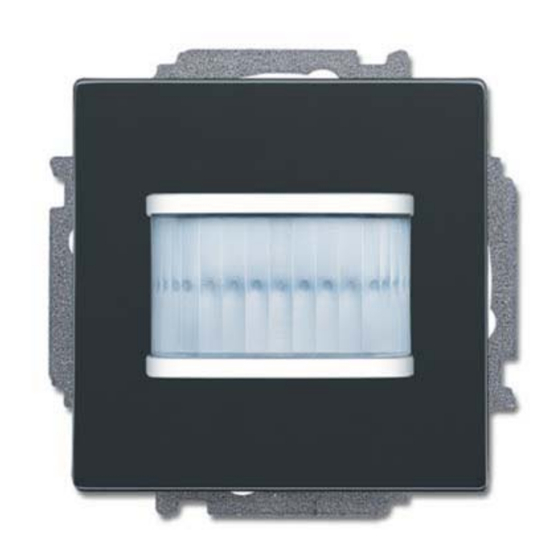
Setup and function Device overview Fig. 2: Overview of devices Movement detector/switch actuator, 1gang, wireless [1] Phase sensing L [2] Mark TOP [3] Terminal strip for cover [4] Bottom terminal block Fig. 3: Cover/sensor [1] Cover/sensor for Movement detector/switch actuator, 1gang, wireless Technical Reference Manual 2CKA001473B9194 │10... -
Page 11: Technical Data
Technical data Technical data Designation Value Operating voltage 230 V AC, 50/60 Hz L, N (option), inputs and outputs non- floating Screw-type terminal: Connection 2 x 2.5 mm² rigid; 2 x 1.5 mm² flexible With protective cover and reset Claw (removable) Transmission protocol free@home wireless... -
Page 12: Dimensional Drawings
Technical data Dimensional drawings Note All dimensions are specified in mm. All device types listed in this manual have the same dimensions. Fig. 4: Dimensions of all described device types (all dimensions in mm) Technical Reference Manual 2CKA001473B9194 │12... -
Page 13: Connection And Installation
Connection and installation Connection and installation Planning instructions NOTE Planning and application instructions for the system are available in system manual for ABB-free@home ® . This can be downloaded via www.abb.com/freeathome. NOTE Transmitter and receiver communicate via radio control. The transmission range depends on the structural conditions. -
Page 14: Detection Range
Connection and installation Detection range Fig. 5: Detection range [1] Mounting heights / detection levels; [2] Detection range (0°C – 36°C); [3] Horizontal reduction of the detection range by masking Circuit diagrams 10 A Fig. 6: Electrical connection Technical Reference Manual 2CKA001473B9194 │14... -
Page 15: Installation
Connection and installation Installation Note The devices have been prepared for installing in flush-mounted boxes in connection with the corresponding mounting plate. The device insert has already been inserted in the mounting plate. To install the device, perform the following steps: Note The sensor must be pulled off the flush-mounted insert... - Page 16 Connection and installation 5. Attach the sensor onto the device insert. Observe the correct position of the terminal strip [1]. Fig. 9: Connection of bus Technical Reference Manual 2CKA001473B9194 │16...
-
Page 17: Commissioning
Commissioning Commissioning Commissioning of the device is always carried out via the Web-based surface of the System Access Point. It is assumed that the basic commissioning steps of the overall system have already been carried out. Knowledge about the Web-based commissioning software of the System Access Point is assumed. -
Page 18: Coupling Of Wireless Devices With The System Access Point
Commissioning Coupling of wireless devices with the System Access Point free@home wireless devices must first be coupled with the System Access Point before they can be used in a project. The devices exchange a security key during the coupling process. Communication between devices is carried out encrypted after coupling and they are firmly connected with the System Access Point. - Page 19 Commissioning 6.1.1.1 Resetting the wireless device to the factory settings 1. De-energize the free@home wireless device. 2. Keep the button at the bottom left pressed. 3. Re-energize the device. The LED flashes slowly for 10 seconds, then fast for 5 seconds and then goes out. The factory settings are restored and the device can now be programmed again.
-
Page 20: Allocation Of Devices And Definition Of Channels
Commissioning Allocation of devices and definition of channels The devices connected to the system must be identified, i.e. they are allocated to a room according to their function and are given a practical name. The allocation is made via the allocation function of the Web-based user interface of the System Access Point. - Page 21 Commissioning 6.2.1 Add device 1. In the "Add devices" bar select the desired application and pull it via drag-and-drop into the floor plan. Fig. 11: Dragging the application from the add bar A pop-up window opens which lists all the devices that are connected to the bus and suitable for the selected application.
- Page 22 Commissioning Fig. 12: Pop-up window with the suitable devices Technical Reference Manual 2CKA001473B9194 │22...
- Page 23 Commissioning Identification The device can be identified via the serial number or via switching. Identification via serial number Fig. 13: Identification via serial number Compare the serial number and the short ID of the identification label, which is glued on the ■...
- Page 24 Commissioning Identification via switching (only suitable for actuators) Fig. 14: Identification via switching 1. Select a device and a channel from the list. 2. Press the button in the detailed view of the device. The connected load is switched. 3. Repeat the last two steps until you have located the searched for device. Technical Reference Manual 2CKA001473B9194 │24...
- Page 25 Commissioning Specifying a name Fig. 15: Specifying a name 1. Enter a name that is easy to understand and under which the application is to be displayed later, e.g. "Movement detector". 2. Press the tick at the bottom right. This takes over the entry. Note The settings of the device can be adjusted via the Web-based user interface of the System Access Point.
-
Page 26: Setting Options Per Channel
Commissioning Setting options per channel General settings and special parameter settings must be made for each channel. The settings are made via the allocation function of the Web-based user interface of the System Access Point. Select device Fig. 16: Select device 1. - Page 27 Commissioning 6.3.1.1 Parameter settings of movement detectors/switch actuators, 1gang Actuator settings [1] Changing the name [2] Deleting the channel [3] Switching of the actuator via the button [4] Selection of a different icon [5] Setting the switch-off delay in seconds –...
-
Page 28: Links
Commissioning Links The sensors and actuators created via the allocation function can now be linked with each other. This allows simple switch-off circuits or two-way circuits to be implemented. The linking in the list view is made via the linking function of the Web-based user interface of the System Access Point. - Page 29 Commissioning 6.4.1 Linking actuator and sensor Fig. 20: Linking actuator and sensor 1. On the working area select the sensor [1] that is to be linked with the actuator. 2. Select the actuator [2] that is to be served by the sensor. 3.
- Page 30 Commissioning 6.4.2 Linking an actuator with an additional sensor Fig. 21: Linking an actuator with an additional sensor 1. On the working area select the second sensor [1] that is to be linked with the actuator. 2. Select the actuator [2] that is to be served by the sensor. 3.
-
Page 31: Update
Update Update A firmware update is carried out via the Web-based user interface of the System Access Point. Operation The devices respond to moving body heat and switch on the lights. They have been pre- programmed accordingly. Action by the user is not necessary. Maintenance The device is maintenance-free. -
Page 32: Diagnosis Of Faults
Maintenance Diagnosis of faults If the device does not function correctly, the L leading edge control can be measured via the phase sensor (L) and determined whether the device carries current after being connected. If it carries current, the cause of the fault is not the electronic insert. Fig. -
Page 33: Notes
Notes Notes Technical Reference Manual 2CKA001473B9194 │33... -
Page 34: Index
Index Index A N Actuator ................. 9 Notes ..................33 Add device ................21 O Allocation of devices ............20 Operation ................31 C Overview of types ..............9 Circuit diagrams ............. 14, 15 P Cleaning ................31 Commissioning ..............17 Parameter settings Connection and installation .......... - Page 35 A member of the ABB Group Notice We reserve the right to make Busch-Jaeger Elektro GmbH technical changes at all times as PO box well as changes to the contents of 58505 Lüdenscheid this document without prior notice. The detailed specifications agreed Freisenbergstraße 2...