Advertisement
Available languages
Available languages
Quick Links
MITSUBISHI ELECTRIC
Programmable
Controllers
Installation Manual for
Extension Blocks of the FX
Series
2NC
Art-no.: 212633 ENG, Version A, 10062009
Safety Information
For qualified staff only
This manual is only intended for use by properly trained and qualified elec-
trical technicians who are fully acquainted with automation technology
safety standards. All work with the hardware described, including system
design, installation, setup, maintenance, service and testing, may only be
performed by trained electrical technicians with approved qualifications
who are fully acquainted with the applicable automation technology safety
standards and regulations.
Proper use of equipment
The programmable controllers (PLC) of the MELSEC FX
2NC
only intended for the specific applications explicitly described in this man-
ual or the manuals listed below. Please take care to observe all the installa-
tion and operating parameters specified in the manual. All products are
designed, manufactured, tested and documented in agreement with the
safety regulations. Any modification of the hardware or software or
disregarding of the safety warnings given in this manual or printed on the
product can cause injury to persons or damage to equipment or other prop-
erty. Only accessories and peripherals specifically approved by
MITSUBISHI ELECTRIC may be used. Any other use or application of the
products is deemed to be improper.
Relevant safety regulations
All safety and accident prevention regulations relevant to your specific
application must be observed in the system design, installation, setup,
maintenance, servicing and testing of these products.
In this manual special warnings that are important for the proper and safe
use of the products are clearly identified as follows:
P
DANGER:
Personnel health and injury warnings.
Failure to observe the precautions described here
can result in serious health and injury hazards.
E
CAUTION:
Equipment and property damage warnings.
Failure to observe the precautions described here
can result in serious damage to the equipment or
other property.
Further Information
The following manuals contain further information about the modules:
b
FX
2NC
Series User´s Manual – Hardware Edition
b
FX
Series User´s Manual – Hardware Edition
3UC
These manuals are available free of charge through the internet
(www.mitsubishi-automation.com).
If you have any questions concerning the programming and operation of
the equipment described in this manual, please contact your relevant sales
office or department.
Specifications
General specifications
The general specifications are equivalent to the PLC main units of the
MELSEC FX
series. For further information, please refer to the FX
3UC
Series Hardware Manual.
Power consumption
The power for the extension blocks is supplied by the base unit or an exten-
sion power supply unit.
Item
Power consumption
FX
-16EX-DS
2.2 W*
2NC
Input
FX
-16EX-T-DS
2.2 W*
2NC
extension
FX
-32EX-DS
4.2 W*
2NC
FX
-16EYT-DSS
0.35 W
2NC
Output
FX
2NC
-16EYR-T-DS
2.2 W
extension
FX
-32EYT-DSS
0.7 W
2NC
*
Includes input current (5 mA per point)
Input specifications
Item
Specification
series are
FX
-16EX-DS
16
2NC
Number of
FX
-16EX-T-DS
16
2NC
input points
FX
2NC
-32EX-DS
32
Input circuit insulation
Photocoupler insulation
Input form
Sink or source
24 V DC (+20 % / -15 %);
Input signal voltage
Ripple voltage (p-p) 5 % or less
Input impedance
4.3 kΩ
Input signal current
5 mA (at 24 V DC)
ON
3.5 mA
Input sensitivity current
OFF
1.5 mA
Input response time
Approx. 10 ms
¼ No-voltage contact input
Sink input
¼ NPN open collector transistor
Connect-
able
¼ No-voltage contact input
sensors
Source input
¼ PNP open collector transistor
LED lights when input is
Input operation display
switched on
FX
-16EX-DS
2NC
Input con-
Connector
FX
-32EX-DS
2NC
necting
type
FX
-16EX-T-DS
Terminal block
2NC
Output specifications
Transistor Output Modules (FX
- EYT-DSS)
2NC
3UC
Item
Specification
Number of
FX
-16EYT-DSS
16
2NC
output
FX
-32EYT-DSS
32
points
2NC
Circuit insulation
Photocoupler insulation
Output form
Transistor, source
External power supply
5 to 30 V DC
¼ 0.1 A per output
Resistance load
¼ 0.8 A per group
Max. load
Inductive load
2.4 W (24 V DC) per output
Minimum load
—
≤ 0.1 mA at 30 V DC
Open circuit leakage current
≤ 1.5 V
ON voltage
OFF
ON
Response
≤ 0.2 ms with 100 mA (24 V DC)
time
ON
OFF*
Display of output operation
LED lights when output is driven
Output connecting type
Connector
Number of
FX
-16EYT-DSS
1 group with 16 outputs
2NC
output
points per
FX
-32EYT-DSS
2 groups with 16 outputs each
2NC
+V„ termi-
nal
*
The transistor OFF time is longer under lighter loads. For example,
with a load of 40 mA at 24 V DC, the response time is approx. 0.3 ms.
When response performance is required under lighter loads, install a
resistor in parallel with the load to increase the load current of the out-
put.
Relay Output Module FX
-16EYR-T-DS
2NC
Item
Specification
Number of output points
16
Circuit insulation
Relay
Output form
Relay
External power supply
max. 30 V DC / max. 240 V AC
¼ 2 A per output
Resistance load
¼ 4 A per group*
Max. load
Inductive load
80 VA
Minimum load
5 V DC, 2 mA
Open circuit leakage current
—
ON voltage
—
OFF
ON
Response
Approx. 10 ms
time
ON
OFF
Display of output operation
LED lights when output is driven
Output connecting type
Terminal block
Number of output points per
2 groups with 8 outputs each
COM„ terminal
*
When using one COM
terminal, make sure that the total load cur-
rent of 8 resistance load outputs (1 group) is 4 A or less.
When connecting two COM
terminals outside the PLC, the total
load current for 8 resistance load outputs is 8 A or less.
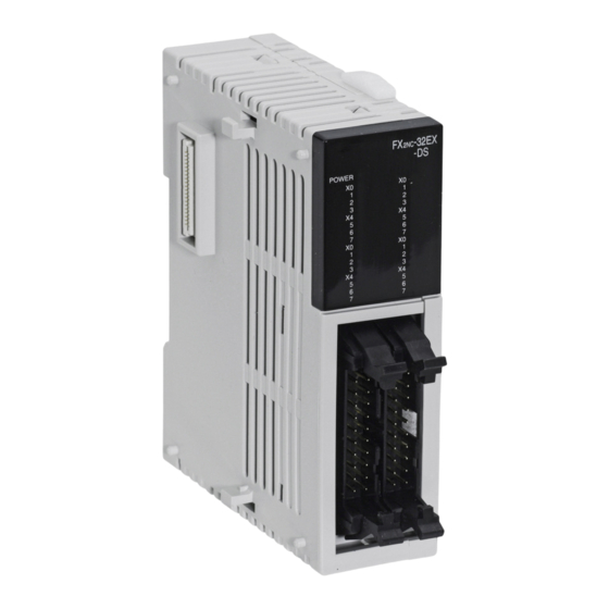
External dimensions and weight
Connector type extension blocks
W
13
74
Terminal type extension blocks
W
15
74
All dimensions are in "mm".
Model name
Connecting type
Width (W)
FX
-16EX-DS
2NC
14.6 mm
FX
-16EYT-DSS
2NC
Connector
FX
-32EX-DS
2NC
26.2 mm
FX
-32EYT-DSS
2NC
FX
2NC
-16EX-T-DS
20.2 mm
Terminal block
FX
-16EYR-T-D
2NC
24.2 mm
S
Weight
0.15 kg
0.2 kg
0.2 kg
0.2 kg
Advertisement

Related Manuals for Mitsubishi Electric FX2NC-16EX-DS


Summary of Contents for Mitsubishi Electric FX2NC-16EX-DS
- Page 1 Only accessories and peripherals specifically approved by Input form Sink or source MITSUBISHI ELECTRIC may be used. Any other use or application of the products is deemed to be improper. Model name Connecting type...
- Page 2 PLC's ventilation slits when the installation work is com- pleted to prevent overheating of the PLC. 14 mm MITSUBISHI Mitsubishi Electric Europe B.V. /// FA - European Business Group /// ELECTRIC Germany /// Tel.: +49(0)2102-4860 /// Fax: +49(0)2102-486112 /// FACTORY AUTOMATION...
- Page 3 Technische Daten MITSUBISHI ELECTRIC Allgemeine Betriebsbedingungen Daten der Ausgänge Abmessungen und Gewichte Die allgemeinen Betriebsbedingungen entsprechen denen der Transistor-Ausgangsmodule (FX - EYT-DSS) Erweiterungsmodule mit Steckanschluss SPS-Grundgeräte der MELSEC FX -Serie. Weitere Informationen fin- Speicher- den Sie in der Hardware-Beschreibung zur MELSEC FX -Serie.
- Page 4 Installationsarbeiten muss diese Abdeckung wieder entfernt 8 mm MITSUBISHI werden, um eine Überhitzung der Steuerung zu vermeiden. Mitsubishi Electric Europe B.V. /// FA - European Business Group /// ELECTRIC Germany /// Tel.: +49(0)2102-4860 /// Fax: +49(0)2102-486112 /// 14 mm FACTORY AUTOMATION...
- Page 5 Le temps de coupure du transistor (OFF) est supérieur avec des char- -16EX-DS par MITSUBISHI ELECTRIC en association avec les automates program- 24 V CC (+20 % / -15 %); ges plus faibles. Exemple : avec une charge de 40 mA sous 24 Vcc, le...
- Page 6 être retiré afin d'éviter une surchauffe de l'automate. 2,6 mm 8 mm MITSUBISHI Mitsubishi Electric Europe B.V. /// FA - European Business Group /// ELECTRIC Germany /// Tel.: +49(0)2102-4860 /// Fax: +49(0)2102-486112 /// 14 mm FACTORY AUTOMATION...
-
Page 7: Specifiche Tecniche
MELSEC FX si possono utilizzare solo unità carico basso. Ad esempio il tempo di risposta con una corrente di aggiuntive o di espansione consigliate da MITSUBISHI ELECTRIC. circuito a logica negativa (sink) o carico di 40 mA a 24 V DC è ca. 0,3 ms. Se ad un carico inferiore si Potenziale per segnali d’ingresso... - Page 8 A conclusione dei lavori di 8 mm installazione sarà necessario rimuovere tale copertura onde MITSUBISHI Mitsubishi Electric Europe B.V. /// FA - European Business Group /// evitare fenomeni di surriscaldamento al sistema di controllo. ELECTRIC 14 mm Germany /// Tel.: +49(0)2102-4860 /// Fax: +49(0)2102-486112 ///...
- Page 9 Sonexión menor tiempo de respuesta con una carga inferior, debería conectarse una MITSUBISHI ELECTRIC. Todo empleo o aplicación distinto o más amplio del enchufable resistencia en paralelo con la carga para aumentar la corriente de salida.
- Page 10 8 mm cubierta para evitar un sobrecalentamiento del control. MITSUBISHI Mitsubishi Electric Europe B.V. /// FA - European Business Group /// 14 mm ELECTRIC Germany /// Tel.: +49(0)2102-4860 /// Fax: +49(0)2102-486112 /// FACTORY AUTOMATION www.mitsubishi-automation.com...
-
Page 11: Технические Данные
Технические данные MITSUBISHI ELECTRIC Общие условия эксплуатации Данные выходов Размеры и масса Общие условия эксплуатации аналогичны базовым блокам контроллеров Модули расширения с разъёмами транзисторные выходы приборов (FX - EYT-DSS) серии FX . См. описание аппаратной части для серии FX Показатель... - Page 12 прорези прилагаемой крышкой. По окончании всех монтажных 8 мм работ эту крышку необходимо снова снять во избежание перегрева ПЛК. 14 мм MITSUBISHI Mitsubishi Electric Europe B.V. /// FA - European Business Group /// ELECTRIC Germany /// Tel.: +49(0)2102-4860 /// Fax: +49(0)2102-486112 /// FACTORY AUTOMATION www.mitsubishi-automation.com...
-
Page 13: Dane Techniczne
Postać obwodu wejściowego Sink lub source * Przy mniejszych obciążeniach czas wyłączania tranzystora jest dłuższy. Na peryferyjny, specjalnie zatwierdzone przez MITSUBISHI ELECTRIC. Użycie przykład, przy obciążeniu prądem 40 mA i napięciu 24 V DC, czas odpowiedzi -16EX-DS każdych innych produktów lub ich zastosowanie, uznawane jest za 24 V DC (+20 % / -15 %);... - Page 14 Aby nie 8 mm dopuścić do przegrzania sterownika PLC, po zakończeniu instalacji MITSUBISHI Mitsubishi Electric Europe B.V. /// FA - European Business Group /// należy upewnić się, że opaska została usunięta z jego szczelin 14 mm ELECTRIC Germany /// Tel.: +49(0)2102-4860 /// Fax: +49(0)2102-486112 ///...
- Page 15 és egyéb tulajdon károsodását száma +V -32EYT-DSS 2 csoport, mindegyik 16 kimenettel Bemenő áramkör szigetelése Optikai leválasztás okozhatja. Kifejezetten csak a MITSUBISHI ELECTRIC által jóváhagyott kapcsonként tartozékok és perifériák használata megengedett. A termékek bármely más Csatlakoztatás használata vagy alkalmazása helytelen. Bemenet típusa Nyelő...
- Page 16 PLC melegedésének elkerülése 14 mm érdekében, győződjön meg róla, hogy a porvédő burkolatot eltávolította a PLC szellőzőnyílásairól. MITSUBISHI Mitsubishi Electric Europe B.V. /// FA - European Business Group /// ELECTRIC Germany /// Tel.: +49(0)2102-4860 /// Fax: +49(0)2102-486112 /// FACTORY AUTOMATION www.mitsubishi-automation.com...
-
Page 17: Bezpečnostní Informace
Rozměry „mm“. Smějí se používat pouze příslušenství a periférie specificky schválené společ- vstupních -16EX-T-DS -32EYT-DSS 2 skupiny s 16 výstupy každá svorku +V ností MITSUBISHI ELECTRIC. Jakékoli jiné aplikace produktu budou považovány bodů za nesprávné. -32EX-DS Název modelu Připojení Šířka (B) Hmotnost Doba potřebná... - Page 18 Po ukončení všech instalačních prací kryt opět sejměte, aby při provozu nedošlo k přehřátí řídicí jednotky. MITSUBISHI Mitsubishi Electric Europe B.V. /// FA - European Business Group /// ELECTRIC Germany /// Tel.: +49(0)2102-4860 /// Fax: +49(0)2102-486112 /// FACTORY AUTOMATION...