Advertisement
Quick Links
Installation Instructions
Models HTRI-S / HTRI-D / HTRI-R
Addressable Switch Interface Modules
INTRODUCTION
PROGRAMMING
INSTRUCTIONS
P/N 315-033300-2
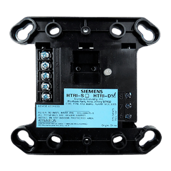
The SIEMENS Model HTRI Series Addressable
modules, shown in Figure 1, interface direct
shorting devices to the FireFinder-XLS System’s
DLC loop circuit.
The HTRI modules are available in three models.
The HTRI-S and HTRI-R can monitor a normally
open or closed dry contact. The HTRI-S can only
monitor and report the status of the contact,
while the HTRI-R incorporates an addressable
Form C relay. The HTRI-D is a dual input module
that supervises and monitors two sets of
dry contacts.
Refer to Figure 2 to locate the opening on the HTRI cover that allows access to the
programming holes which are on the HTRI printed circuit board.
To connect the HTRI to the
DPU Programmer/Tester,
insert the plug from the DPU
cable provided with the
Programmer/Tester into the
opening on the front of the
HTRI. Be sure to insert the
locating tab on the plug into
the slot for the locating tab on
the HTRI as shown in Figure 2.
To prevent potential damage
to the DPU DO NOT connect
an HTRI to the DPU until at
least one wire is removed
from terminals 1 or 2 of the
HTRI.
SLOT FOR
LOCATING TAB
1
2
3
4
5
LOCATING
TAB
Figure 2
Connecting The DPU Plug
Siemens Building Technologies
Figure 1
HTRI Module
PROGRAMMING
HOLES
HTRI-S/-D/-R
MODULE
8
7
6
PLUG FROM
DPU
PROGRAMMER/
TESTER
Fire Safety
Advertisement

Related Manuals for Siemens HTRI-S


Summary of Contents for Siemens HTRI-S
- Page 1 DLC loop circuit. The HTRI modules are available in three models. The HTRI-S and HTRI-R can monitor a normally open or closed dry contact. The HTRI-S can only monitor and report the status of the contact, while the HTRI-R incorporates an addressable Form C relay.
- Page 2 FOR DOUBLE GANG BOX to create two separate compartments within the backbox to separate the wires, as shown in Figure 4. USE P/N 330-096384 FOR 4-INCH SWITCHBOX Figure 4 Installing the HTRI-R Control Module Barrier Siemens Building Technologies P/N 315-033300-2 Fire Safety...
- Page 3 Line to shield Max line size: 14 AWG Min line size: 18 AWG Figure 7 6. Relay contact ratings: HTRI-S Wiring 4A, 125 VAC resistive 4A, 30 VDC resistive Inductive: LINE 1 3.5A, 120 VAC (0.6 P .F .) TO NEXT LINE 2 3.0A, 30 VDC (0.6 P .F .)
- Page 4 HTRI-S/-R draws 1mA HTRI-D draws 1mA Figure 9 Security Point (1076) Wiring Connections Terminal 5 of the HTRI-S/-D/-R must be connected to a known good earth ground for proper operation. MOUNTING Addressable Interface SIEMENS Models HTRI-S, HTRI-D, and HTRI-R mount directly into a (user supplied) double gang or 4 inch switchbox.