ABB Navigator 540 Instruction Manual
Hide thumbs
Also See for Navigator 540:
- Instruction manual (17 pages) ,
- Operating instructions manual (76 pages) ,
- Operating instructions manual (88 pages)
Table of Contents
Advertisement
Quick Links
—
A B B M E A S U R E M E N T & A N A LY T I C S | I N S T R U C T I O N M A N U A L S U P P L E M E N T | C O M/AW T 5 4 0/ P B - E N R E V. C
Navigator 540
Transmitter
Introduction
—
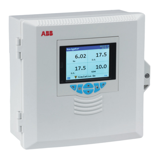
Navigator 540
transmitter
The Navigator 500 range of analyzers from ABB are
designed for high purity water treatment
applications and power cycle chemistry monitoring.
The analysis and signal conditioning is conducted
within the Navigator 550's advanced wet-section
that houses the sensing technology. The accurate
measurement result is transmitted digitally to the
Navigator AWT540 transmitter.
Communications supplement
Measurement made easy
The following parameters are available in the
Navigator 500 range:
Navigator 500
• Dissolved oxygen
• Hydrazine
• Sodium
This publication provides PROFIBUS®, Modbus® and
Ethernet connection/configuration details together
with PROFIBUS and Modbus reference tables for the
Navigator AWT540 transmitter.
Advertisement
Table of Contents

Related Manuals for ABB Navigator 540


Summary of Contents for ABB Navigator 540
- Page 1 Measurement made easy Introduction — Navigator 540 transmitter The Navigator 500 range of analyzers from ABB are The following parameters are available in the designed for high purity water treatment Navigator 500 range: Navigator 500 applications and power cycle chemistry monitoring.
- Page 2 For more information Further publications for the Navigator 500 series are available for free download from www.abb.com/analytical or by scanning these codes: Navigator ADS550 Navigator AHM550 Navigator ASO550 Dissolved oxygen Hydrazine analyzer Sodium analyzer analyzer Search for or click on...
-
Page 3: Table Of Contents
Host computer serial communications ....... 13 Two-wire and four-wire connection ......14 Pull-up and pull-down resistors ........14 Termination resistor ........... 14 Serial connections ............14 6 Ethernet communications ........15 Ethernet connection ........... 15 Navigator 540 | Transmitter | COM/AWT540/PB–EN Rev. C 3... -
Page 4: Health & Safety
The signal word 'IMPORTANT Electrical Equipment for Measurement, Control and Laboratory (NOTE)' does not indicate a dangerous or harmful Use' and complies with US NEC 500, NIST and OSHA. situation. COM/AWT540/PB–EN Rev. C | Navigator 540 | Transmitter... -
Page 5: Product Symbols
This symbol, when noted on a product, indicates a ABB is committed to ensuring that the risk of any potential hazard which could cause serious personal environmental damage or pollution caused by any of injury and / or death. -
Page 6: Communications Overview
2.3.2 PROFIBUS and ABB products Navigator AWT540 utilizes PROFIBUS DP as this protocol is optimized for high speed and low connection costs (see www.abb.com/fieldbus and follow the PROFIBUS link). COM/AWT540/PB–EN Rev. C | Navigator 540 | Transmitter... -
Page 7: Communication Level
Read Only Back Select Calibrate Advanced Ethernet – refer to Section 6, page 15. Service Back Select 3. Use the key to scroll to Advanced and press the key (below the Select prompt). Navigator 540 | Transmitter | COM/AWT540/PB–EN Rev. C... -
Page 8: Profibus Communications
PROFIBUS International / PROFIBUS User level Organization (www.profibus.com) PROFIBUS-PA transducer block DP / PA link Navigator AWT540 Totalizer function block transmitter PROFIBUS-P Table 4.1: Acronyms and abbreviations Fig. 4.1: Typical PROFIBUS network COM/AWT540/PB–EN Rev. C | Navigator 540 | Transmitter... -
Page 9: Cable Length
D-type connectors. Positive (+) data line: connect to pin 3 on Suitable PROFIBUS cable (part numbers PCA010, PCA011 and PROFIBUS DP equipment with 9-way PCA012) can be obtained from ABB. Refer to Data Sheet D-type connectors. 10/63-6.46 EN. Braided N / A Cable screen –... -
Page 10: Configuration
(below the Select prompt). when configuring a PROFIBUS bus system. IMPORTANT (NOTE) The Baud Rate is a read-only value. The current Slave Address setting (for example 70) is displayed. COM/AWT540/PB–EN Rev. C | Navigator 540 | Transmitter... -
Page 11: Configuration From The Navigator Awt540 Transmitter
The ABB GSD file (Ident No. 3402) is divided into 2 sections: 4.7 Navigator AWT540-DP PROFIBUS datasheet — General specifications Item Detail PROFIBUS device NAVIGATOR 500 Identification of the device, together with hardware and name (product: Navigator AWT540) software versions, baud rates supported and the possible... -
Page 12: Declaration Of Profibus Conformance
— DPV0 and DPV1 protocol services. — Navigator AWT540-DP device-specific GSD file (ABB_3402.gsd). A copy of the conformance certificate is available for download from the Navigator AWT540 product pages of the ABB website www.abb.com. COM/AWT540/PB–EN Rev. C | Navigator 540 | Transmitter... -
Page 13: Modbus Communications
WARNING – Bodily injury Tx Delay Set a delay to the response from the 50 ms Refer to the Navigator AWT540 Commissioning transmitter in milliseconds. Maximum instruction (CI/AWT540-EN) before making electrical delay 100 ms. connections. Navigator 540 | Transmitter | COM/AWT540/PB–EN Rev. C... -
Page 14: Two-Wire And Four-Wire Connection
— Up to 300 m (984 ft.) – twin twisted pair with overall foil screen and an integral drain wire. — Up to 1200 m (3937 ft.) – twin twisted pair with separate foil screens and integral drain wires. COM/AWT540/PB–EN Rev. C | Navigator 540 | Transmitter... -
Page 15: Ethernet Communications
(the email can be sent to up to 3 recipients). Invert 1 (to 4) If enabled, an email is generated when the Source becomes inactive instead of active. Navigator 540 | Transmitter | COM/AWT540/PB–EN Rev. C... -
Page 16: Appendix A - Profibus Tables
Inactive In manual test Simple Unsigned 8 Inactive In configuration Simple Unsigned 8 Inactive Media card full Simple Unsigned 8 Inactive Media near full Simple Unsigned 8 Inactive Table A.2: Transmitter diagnostics COM/AWT540/PB–EN Rev. C | Navigator 540 | Transmitter... -
Page 17: Sensor Diagnostics
No low calibration solution Simple Unsigned 8 Inactive No high calibration solution Simple Unsigned 8 Inactive No regeneration solution Simple Unsigned 8 Inactive Flow error Simple Unsigned 8 Inactive Table A.4: Sensor 2 diagnostics Navigator 540 | Transmitter | COM/AWT540/PB–EN Rev. C... - Page 18 No low calibration solution Simple Unsigned 8 Inactive No high calibration solution Simple Unsigned 8 Inactive No regeneration solution Simple Unsigned 8 Inactive Flow error Simple Unsigned 8 Inactive Table A.6: Sensor 4 diagnostics COM/AWT540/PB–EN Rev. C | Navigator 540 | Transmitter...
- Page 19 Digital input 3 state Simple Unsigned 8 Digital input 4 state Simple Unsigned 8 Digital input 5 state Simple Unsigned 8 Digital input 6 state Simple Unsigned 8 Table A.7: Multi-stream sensor diagnostics Navigator 540 | Transmitter | COM/AWT540/PB–EN Rev. C...
-
Page 20: Alarm Acknowledgement
Simple Unsigned 8 0 to 255 Start two point calibration sensor 4 Simple Unsigned 8 0 to 255 Start regeneration sensor 4 Simple Unsigned 8 0 to 255 Table A.9: Action commands COM/AWT540/PB–EN Rev. C | Navigator 540 | Transmitter... -
Page 21: Read-Only, Single Precision Float
Sensor 4 – Active calibration slope Simple Float Sensor 4 – Active calibration offset Simple Float Sensor 4 – Last calibration slope Simple Float Sensor 4 – Last calibration offset Simple Float Table A.11: Sensor signals view Navigator 540 | Transmitter | COM/AWT540/PB–EN Rev. C... - Page 22 Sensor 3 – Temperature range high Simple Float Sensor 3 – Temperature range low Simple Float Sensor 4 – Temperature range high Simple Float Sensor 4 – Temperature range low Simple Float Table A.12: Measurement range limits COM/AWT540/PB–EN Rev. C | Navigator 540 | Transmitter...
-
Page 23: Read-Only, 32 Bits
Sensor 2 – Hardware version number Simple Unsigned 16 version Sensor 2 – Hardware version number Simple Unsigned 16 Sensor 2 – Hardware version number Simple Unsigned 16 Table A.16: Sensor hardware version Navigator 540 | Transmitter | COM/AWT540/PB–EN Rev. C... -
Page 24: Read-Only, 8 Bits
Unsigned 8 0 – Disabled Flow sensor fitted 1 – Enabled Sensor 4 – Simple Unsigned 8 0 – Disabled Regeneration hardware fitted 1 – Enabled Table A.17: Sensor type and hardware options COM/AWT540/PB–EN Rev. C | Navigator 540 | Transmitter... -
Page 25: Read-Only Strings
Chart – Trace 3 – Simple Float Range low Chart – Trace 4 – Simple Float Range high Chart – Trace 4 – Simple Float Range low Table A.20: Chart trace range Navigator 540 | Transmitter | COM/AWT540/PB–EN Rev. C... - Page 26 Alarm 4 – Hysteresis Simple Float Alarm 5 – Hysteresis Simple Float Alarm 6 – Hysteresis Simple Float Alarm 7 – Hysteresis Simple Float Alarm 8 – Hysteresis Simple Float Table A.21: Alarm settings COM/AWT540/PB–EN Rev. C | Navigator 540 | Transmitter...
- Page 27 Analog output 2 – Simple Float 22 mA Failure current Analog output 3 – Simple Float 22 mA Failure current Analog output 4 – Simple Float 22 mA Failure current Table A.22: Analog output settings Navigator 540 | Transmitter | COM/AWT540/PB–EN Rev. C...
-
Page 28: Writable, 16 Bits
0 to 9999 seconds Alarm 7 – Time hysteresis Simple Unsigned 16 0 to 9999 seconds Alarm 8 – Time hysteresis Simple Unsigned 16 0 to 9999 seconds Table A.24: Alarm time hysteresis COM/AWT540/PB–EN Rev. C | Navigator 540 | Transmitter... -
Page 29: Writable, 8 Bits
1 – Two months calibration 2 – Three months frequency monthly 3 – Four months 4 – Six months 5 – Twelve months Table A.25: Single-stream sensors – units, filter and scheduled calibration configuration Navigator 540 | Transmitter | COM/AWT540/PB–EN Rev. C... - Page 30 1 – Two months calibration 2 – Three months frequency monthly 3 – Four months 4 – Six months 5 – Twelve months Table A.25: Single-stream sensors – units, filter and scheduled calibration configuration (continued) COM/AWT540/PB–EN Rev. C | Navigator 540 | Transmitter...
- Page 31 1 – Two months calibration 2 – Three months frequency monthly 3 – Four months 4 – Six months 5 – Twelve months Table A.25: Single-stream sensors – units, filter and scheduled calibration configuration (continued) Navigator 540 | Transmitter | COM/AWT540/PB–EN Rev. C...
- Page 32 1 – Two months calibration 2 – Three months frequency monthly 3 – Four months 4 – Six months 5 – Twelve months Table A.25: Single-stream sensors – units, filter and scheduled calibration configuration (continued) COM/AWT540/PB–EN Rev. C | Navigator 540 | Transmitter...
- Page 33 Simple Unsigned 8 Weekly 0 to 7 calibration frequency weekly Scheduled Simple Unsigned 8 Monthly 0 to 5 calibration frequency monthly Table A.26: Multi-stream sensors – units, filter and scheduled calibration configuration Navigator 540 | Transmitter | COM/AWT540/PB–EN Rev. C...
- Page 34 Disabled 0 to 1 0 – Disabled 1 – Enabled Diagnostics log Simple Unsigned 8 Disabled 0 to 1 0 – Disabled 1 – Enabled Table A.28: Data view / log enables COM/AWT540/PB–EN Rev. C | Navigator 540 | Transmitter...
- Page 35 1 to 7 1 – Sunday End day for daylight 2 – Monday saving 3 – Tuesday 4 – Wednesday 5 – Thursday 6 – Friday 7 – Saturday Table A.29: Date display settings Navigator 540 | Transmitter | COM/AWT540/PB–EN Rev. C...
- Page 36 1 – High process 2 – Low process 3 – High latch 4 – Low latch Alarm 6 – Source Simple Unsigned 8 None 0 to 8 See source list Table A.30: Alarm settings COM/AWT540/PB–EN Rev. C | Navigator 540 | Transmitter...
- Page 37 2 – Logarithmic (three decades) 3 – Logarithmic (four decades) Analog output 4 – Simple Unsigned 8 Enabled 0 to 1 0 – Enabled Failure current 1 – Disabled enable Table A.31: Analog output settings Navigator 540 | Transmitter | COM/AWT540/PB–EN Rev. C...
- Page 38 0 and See source list Source 9 to 64 Digital I/O 6 – Simple Unsigned 8 0 to 1 0 – Inverted Polarity inverted 1 – Non inverted Table A.32: Digital I/O settings COM/AWT540/PB–EN Rev. C | Navigator 540 | Transmitter...
-
Page 39: Writable Strings
Chart config tag 2 Simple Visible string Ch 2 Chart config tag 3 Simple Visible string Ch 3 Chart config tag 4 Simple Visible string Ch 4 Table A.35: 3 byte strings Navigator 540 | Transmitter | COM/AWT540/PB–EN Rev. C... -
Page 40: Appendix B - Modbus Tables
Read/Write 16 bit parameters Holding registers Unsigned 16 bit 42000 42999 Read/Write 8 bit parameters Holding registers Unsigned 8 bit 43000 43999 Read/Write string parameters Holding registers Unsigned 8 bit 44000 44999 COM/AWT540/PB–EN Rev. C | Navigator 540 | Transmitter... -
Page 41: Digital I/O Status
Acknowledge alarm 4 30014 Sensor 4 – Temperature Acknowledge alarm 5 Table B.4: Measurement values (input coils) Acknowledge alarm 6 Acknowledge alarm 7 Acknowledge alarm 8 Table B.2: Alarm acknowledgement (output coils) Navigator 540 | Transmitter | COM/AWT540/PB–EN Rev. C... - Page 42 Table B.5: Sensor signals view 30172 Analog output % of full scale AOUT2 30174 Analog output % of full scale AOUT3 30176 Analog output % of full scale AOUT4 Table B.7: Analog outputs COM/AWT540/PB–EN Rev. C | Navigator 540 | Transmitter...
-
Page 43: Read-Only, 32 Bits
Sensor 1 – Hardware version number 32001 Sensor 2 – Hardware version number 32002 Sensor 3 – Hardware version number 32003 Sensor 4 – Hardware version number Table B.12: Sensor hardware version (valid range 1 to 9) Navigator 540 | Transmitter | COM/AWT540/PB–EN Rev. C... -
Page 44: Read-Only 8 Bits
Sensor 4 – 0 – Disabled Flow sensor fitted 1 – Enabled 33011 Sensor 4 – 0 – Disabled Regeneration hardware fitted 1 – Enabled Table B.13: Sensor type and hardware options COM/AWT540/PB–EN Rev. C | Navigator 540 | Transmitter... -
Page 45: Writable Floats
Analog output 1 – Failure current 0 – 22 mA 40082 Analog output 2 – Failure current 40084 Analog output 3 – Failure current 40086 Analog output 4 – Failure current Table B.18: Analog output settings Navigator 540 | Transmitter | COM/AWT540/PB–EN Rev. C... -
Page 46: Writable, 16 Bits
1 – Two months 2 – Three months 3 – Four months 4 – Six months 5 – Twelve months Table B.21: Single-stream sensors – Units, filter and scheduled calibration configuration COM/AWT540/PB–EN Rev. C | Navigator 540 | Transmitter... - Page 47 7 – ppb Table B.21: Single-stream sensors – Units, filter and units 8 – ug/l scheduled calibration configuration (continued) 9 – ug/Kg Table B.21: Single-stream sensors – Units, filter and scheduled calibration configuration (continued) Navigator 540 | Transmitter | COM/AWT540/PB–EN Rev. C...
- Page 48 Table B.21: Single-stream sensors – Units, filter and 1 – Stream 1 scheduled calibration configuration (continued) 2 – Stream 2 3 – Stream 3 Table B.22: Multi-stream sensors – units, filter and scheduled calibration configuration COM/AWT540/PB–EN Rev. C | Navigator 540 | Transmitter...
- Page 49 1 – Two months 2 – Three months 3 – Four months 4 – Six months 5 – Twelve months Table B.22: Multi-stream sensors – units, filter and scheduled calibration configuration (continued) Navigator 540 | Transmitter | COM/AWT540/PB–EN Rev. C...
- Page 50 Analog output 4 – Output type See Analog output 1 – Output type 43120 Analog output 4 – failure current 0 – Enabled enable 1 – Disabled Table B.27: Analog output settings COM/AWT540/PB–EN Rev. C | Navigator 540 | Transmitter...
-
Page 51: Writable Strings
0 – inverted 1 – Non inverted 43149 Relay 6 – Source See Relay 1 – Source 43150 Relay 6 – Polarity 0 – inverted 1 – Non inverted Table B.29: Relay settings Navigator 540 | Transmitter | COM/AWT540/PB–EN Rev. C... -
Page 52: Appendix C - Ranges And Signals
Sensor 4 function check Transmitter failure Transmitter out of specification Transmitter maintenance Transmitter function check Sensor 1 calibration in progress Sensor 2 calibration in progress Sensor 3 calibration in progress Table C.3: Digital signal sources COM/AWT540/PB–EN Rev. C | Navigator 540 | Transmitter... - Page 53 Acknowledgements PROFIBUS is a registered trademark of PROFIBUS and PROFINET International (PI). Modbus is a registered trademark of the Modbus-IDA organization.
- Page 54 We reserve the right to make technical changes or modify the contents of this document without prior notice. With regard to purchase orders, the agreed particulars shall prevail. ABB does not accept any responsibility whatsoever for potential errors or possible lack of information in this document.