Advertisement
Quick Links
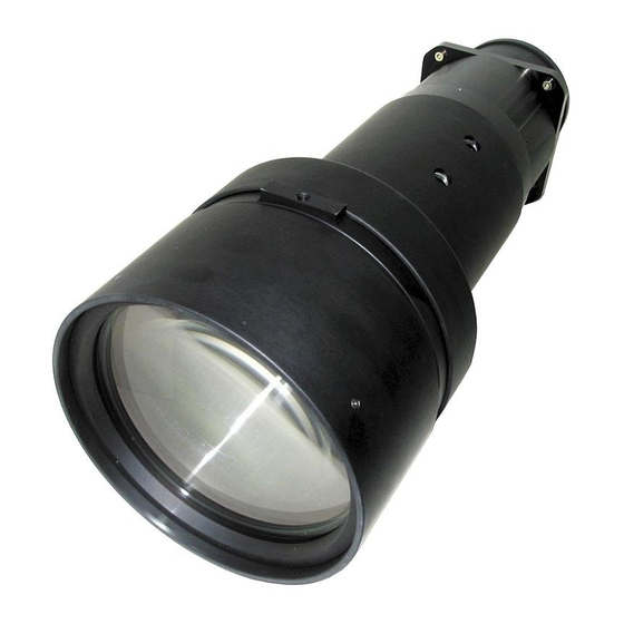
LCD PROJECTOR LENS
MODEL NO. LNS-T03
LENS REPLACEMENT
AND INSTALLATION PROCEDURES
NOTES ON REPLACEMENT AND INSTALLATION
The procedures and the needed pars for lens installation depend on the type of
cabinet. Before installing or replacing the lens, make sure the type of cabinet of your
projector.
When installing or replacing the lens, make sure the Lens Model No. matches with to
your projector. Refer to the catalog, or contact your sales dealer for the proper Lens
Model No.
TYPE OF THE CABINET AND INSTALLATION PROCEDURES
Check the type of cabinet of your projector and follow the respective installation procedure
to install the lens correctly.
Type of the Cabinet (1) (See Page 2)
For lens installation to the other models than above, contact your sales dealer.
Type of the Cabinet (2) (See Page 5)
1AA6P1P4097-- (IDLS)
Advertisement

Related Manuals for Sanyo LNS-T03


Summary of Contents for Sanyo LNS-T03
- Page 1 LCD PROJECTOR LENS MODEL NO. LNS-T03 LENS REPLACEMENT AND INSTALLATION PROCEDURES NOTES ON REPLACEMENT AND INSTALLATION The procedures and the needed pars for lens installation depend on the type of cabinet. Before installing or replacing the lens, make sure the type of cabinet of your projector.
- Page 2 NOTES ON LENS INSTALLATION • Lens installation and replacement should be made by the qualified service per- sonnel. • Be sure to install the lens following this procedure precisely. • The lens cover is attached to the lens for protection. Be sure to remove the lens cover from the lens before installation.
-
Page 3: Cover Plate
LENS REPLACEMENT AND INSTALLATION PROCEDURE Remove 2 Screws A and Remove Lower Lens Cover. Push part B and pull the Lower Lens Cover down and remove it. (See Fig. 1.) Remove 4 Screws C. Pull the Upper Lens Cover toward front and remove it. (See Fig. 2.) Remove 2 Screws D and Cover Plate from the back of the Upper Lens Cover. -
Page 4: Lens Mounting
Remove Lens Protection Cap from the rear (mounting side) of the Projection Lens and attach the lens Attachment to the lens with 4 Screws. (Use screws attached to the lens.) See Fig. 4. LENS ATTACHMENT DRIVER INCLUDED IN THE LENS PACKAGE Part No. - Page 5 Put back the Upper Lens Cover to the projector and Fix the Upper Lens Cover with 4 Screws C. (See Fig. 2.) Put back the Lower Lens Cover to the projector. Fix the Lower Cover with 2 Screws A. (See Fig. 1.) UPPER LENS COVER LOWER LENS...
- Page 6 LENS REPLACEMENT AND INSTALLATION PROCEDURE Remove 2 Screws A and Remove Upper Lens Cover. Push part B and pull the Upper Lens Cover up and remove it. (See Fig. 1.) Remove 4 Screws C. Pull the Lower Lens Cover toward front and remove it. (See Fig. 2.) Remove 2 Screws D and Cover Plate from the back of the Upper Lens Cover.
- Page 7 Remove Lens Protection Cap from the rear (mounting side) of the Projection Lens and attach the lens Attachment to the lens with 4 Screws. (Use screws attached to the lens.) See Fig. 4. DRIVER INCLUDED IN THE LENS PACKAGE Part No. (610 275 6029) Grasp (release lock) the Lens Lock Lever and turn it fully upward.
- Page 8 Put back the Lower Lens Cover to the projector and Fix the Lower Lens Cover with 4 Screws C. (See Fig. 2.) Put back the Upper Lens Cover to the projector. Fix the Upper Cover with 2 Screws A. (See Fig. 1.) UPPER LENS COVER LOWER LENS...