Table of Contents
Advertisement
SIMATIC Ident
Optical Identification
SIMATIC MV500
Operating Instructions
06/2018
C79000-G8976-C494-01
___________________
Preface
___________________
Description
___________________
Safety notes
___________________
Image processing
___________________
Network and system
integration
___________________
Mounting
___________________
Connection
___________________
Commissioning
___________________
Operator control and
monitoring
___________
Process interfacing via an
automation system (PLC,
PC)
___________________
Service and maintenance
___________________
Technical data
___________________
Dimension drawings
___________________
Scope of delivery and
ordering data
___________________
Appendix
___________________
List of abbreviations
___________________
Service & Support
1
2
3
4
5
6
7
8
9
10
11
12
13
A
B
C
Advertisement
Table of Contents

Related Manuals for Siemens SIMATIC MV540 H


Summary of Contents for Siemens SIMATIC MV540 H
- Page 1 ___________________ Preface ___________________ Description ___________________ SIMATIC Ident Safety notes ___________________ Image processing Optical Identification SIMATIC MV500 ___________________ Network and system integration ___________________ Mounting Operating Instructions ___________________ Connection ___________________ Commissioning ___________________ Operator control and monitoring ___________ Process interfacing via an automation system (PLC, ___________________ Service and maintenance ___________________...
- Page 2 Note the following: WARNING Siemens products may only be used for the applications described in the catalog and in the relevant technical documentation. If products and components from other manufacturers are used, these must be recommended or approved by Siemens. Proper transport, storage, installation, assembly, commissioning, operation and maintenance are required to ensure that the products operate safely and without any problems.
-
Page 3: Preface
Valid for devices/licenses with the following article numbers Device/license Article number SIMATIC MV540 S 6GF3540-0CD10 SIMATIC MV540 H 6GF3540-0GE10 SIMATIC MV560 X 6GF3560-0HE10 The optical readers of the SIMATIC MV500 series can be used for optical identification applications in manufacturing and logistics. Typical applications are product tracking and production control. - Page 4 We point out that the contents of this product documentation shall not become a part of or modify any prior or existing agreement, commitment or legal relationship. The Purchase Agreement contains all obligations of Siemens AG and the complete and exclusive warranty conditions. Any statements on the device versions described in the manual do not create new warranties or modify the existing warranty.
- Page 5 Siemens’ products and solutions undergo continuous development to make them more secure. Siemens strongly recommends that product updates are applied as soon as they are available and that the latest product versions are used. Use of product versions that are no longer supported, and failure to apply the latest updates may increase customers’...
- Page 6 ● Keep the software up to date. Keep yourself informed regularly about safety updates for the product. You can find information about this at Link: (http://www.siemens.com/industrialsecurity) ● Activate only protocols that you actually need to use the device. ● Limit access to the device using a firewall or rules in an access control list (ACL).
- Page 7 Preface Firmware encryption The firmware itself is signed and encrypted. This ensures that only authentic firmware can be downloaded to the device. Secure/non-secure protocols ● Check whether it is necessary to use SNMPv1. SNMPv1 is classified as non-secure. Make use of the possibility to prevent write access. The product offers corresponding settings for this.
- Page 8 Trademarks The following and possibly other names not identified by the registered trademark sign ® registered trademarks of Siemens AG: SIMATIC ®, SIMATIC NET ®, SIMATIC MV ®, SIMATIC RF ®, SIMATIC Sensors ® SIMATIC MV500 Operating Instructions, 06/2018, C79000-G8976-C494-01...
-
Page 9: Table Of Contents
Table of contents Preface ..............................3 Description ............................13 Area of application ........................13 Product characteristics......................14 Design of the SIMATIC MV540 ....................17 Structure of the nameplate ..................... 18 System configuration ......................19 System components ....................... 20 Functional description ......................21 Safety notes ............................ - Page 10 Table of contents System configuration via the Ethernet interface with switch ..........56 System setup via the RS-232 interface ................. 57 System configuration with CM and RFID reader ..............58 System configuration with CM and auto-trigger ..............59 System configuration with WinCC flexible/HTML browser and switch ........60 System configuration with external ring light .................
- Page 11 Table of contents Control with FB 79 ........................ 126 9.4.1 Assignment of the interfaces relevant to PROFINET IO ............126 9.4.2 Select operating modes using the control/status byte ............131 9.4.3 Example program for data exchange if code length ≤ 27 bytes ........... 136 9.4.4 Programming data fragmentation ..................
- Page 12 Table of contents 11.4 Technical specifications of ring light (external) ..............200 Dimension drawings ..........................201 12.1 SIMATIC MV540 ........................201 12.2 Built-in ring lights for SIMATIC MV500 ................201 12.3 D65 protective tube for SIMATIC MV500 ................202 12.4 D65 protective tube extension .....................
-
Page 13: Description
Description Area of application The products of the SIMATIC MV500 series are optical readers designed specifically for the recognition and processing of numerous machine-readable codes and plain text in industrial production. The optical readers provide a wide range of options for identification: ●... -
Page 14: Product Characteristics
Description 1.2 Product characteristics Communication interfaces The optical readers have all the conventional communications interfaces of industrial sensors and can therefore be connected to a wide variety of systems. Through the communications module interface, they can also be seamlessly combined with the communications modules (ASM/CM), for example, via PROFIBUS. - Page 15 Description 1.2 Product characteristics ● RS232 with TxD and RxD ● 2 configurable DI/DQs Extended communication via communication modules ● ASM 456 for PROFIBUS DP/V1 ● RF120C, RF170C and RF180C for PROFINET Power over Ethernet Integrate power supply via Ethernet cable (PoE) Robust construction, suitable for industry Class of protection IP67 With screw-on protective lens barrel...
- Page 16 Description 1.2 Product characteristics Operation on the device Fast, uncomplicated connection between PC and reader without installed software using the "CONNECT" button. Quick adaption to the reading situation using the "READ" button. Web Based Management (WBM) ● Completely installation-free ● Modern HTML5 design ●...
-
Page 17: Design Of The Simatic Mv540
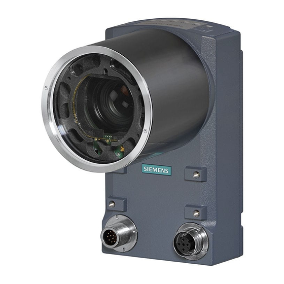
Description 1.3 Design of the SIMATIC MV540 Design of the SIMATIC MV540 The following figure shows the design of the SIMATIC MV540 optical reader. ① ④ LED display Combination interface for power supply, DI/DQ, RS232 and CM (M12, 12-pin) ② ⑤... -
Page 18: Structure Of The Nameplate
Description 1.4 Structure of the nameplate Structure of the nameplate The nameplate is located on the housing of the optical reader and shows the article number and other important product information. ① ⑧ Manufacturer Disposal label ② ⑨ Product designation Data matrix code ③... -
Page 19: System Configuration
Description 1.5 System configuration System configuration The following figure shows a typical system configuration with a SIMATIC MV540 optical reader. ① Optical sensor or light barrier (for trigger signal) ② Object with code Figure 1-3 Example of a system configuration on a production line (illustrated with SIMATIC MV540) SIMATIC MV500 Operating Instructions, 06/2018, C79000-G8976-C494-01... -
Page 20: System Components
Description 1.6 System components System components Optical reader To equip an application with optical readers, you need the following hardware components: ● SIMATIC MV500 optical reader ● Lens suitable for code size and read distance ● Ring light ● Protective lens barrel ●... -
Page 21: Functional Description
Description 1.7 Functional description Functional description Image acquisition The optical readers detect the object characteristics required for the task using digital image acquisition. Following image acquisition, the image is analyzed by a powerful digital signal processor. Depending on the application, multilevel complex algorithms are used during the analysis: ●... - Page 22 Description 1.7 Functional description Processing The actual processing is triggered by different events. ● In the simplest situation, the optical reader generates the trigger event itself. Optical readers have an auto-trigger function for this purpose. ● Depending on the application, it may be advisable to provide the trigger event via the I/O cable.
- Page 23 Description 1.7 Functional description Compatibility with MV400 The functions, communication protocols and configurations are largely compatible with the devices of the SIMATIC MV400 series. The device configurations for these devices can be imported into the readers of the SIMATIC MV500, enabling a seamless transition from SIMATIC MV400 to MV500.
- Page 24 Description 1.7 Functional description SIMATIC MV500 Operating Instructions, 06/2018, C79000-G8976-C494-01...
-
Page 25: Safety Notes
Siemens. This product can only function correctly and safely if it is transported, stored, set up, and installed correctly, and operated and maintained as recommended. - Page 26 Safety notes System expansions Install only system expansions that are intended for this device. Installing other expansions can damage the system or violate the safety provisions and regulations for radio interference suppression. You can obtain information on system expansions suitable for installation from the technical customer service or from the sales office responsible for your area.
- Page 27 Safety notes Connecting the 24 V DC power supply WARNING Requirement: Safe extra low voltage The device should only be connected to a 24 V DC power supply which satisfies the requirements of safe extra low voltage (SELV). When the device is operated on a wall, in an open rack or other similar locations, an NEC Class 2 current source is needed for compliance with UL requirements (according to UL 60950-1).
- Page 28 Safety notes Use in an area of plants with high-energy radiation NOTICE Protection of the image sensor from damaging radiation When the SIMATIC MV500 optical reader is used in an environment of plants with high- energy radiation, for example, laser light or arcs, the image sensor of the optical reader must be protected from damaging radiation.
-
Page 29: Image Processing
Image processing Code reading (1D/2D codes) 3.1.1 Area of application and examples The optical reader reads the types of code listed below. Two-dimensional codes ● DMC ● PDF417 ● QR ● DotCode One-dimensional codes ● Codabar ● Code 32 ● Code 39 (without checksum) ●... -
Page 30: Applications For Two-Dimensional Codes
Image processing 3.1 Code reading (1D/2D codes) 3.1.1.1 Applications for two-dimensional codes Below, you can find several examples of data matrix codes, QR codes, PDF417 codes and dot codes: Printed code Laser code (plastic surface) Laser code (pcb) Code created with an ink jet printer. Punched code Data Matrix ECC080 SIMATIC MV500... - Page 31 Image processing 3.1 Code reading (1D/2D codes) Data Matrix ECC100 Data Matrix ECC140 Printed QR code Printed PDF417 code DotCodes SIMATIC MV500 Operating Instructions, 06/2018, C79000-G8976-C494-01...
-
Page 32: Applications For One-Dimensional Codes
Image processing 3.1 Code reading (1D/2D codes) 3.1.1.2 Applications for one-dimensional codes Codabar Code 32 Code 39 Code 93 Code 128 EAN 8 SIMATIC MV500 Operating Instructions, 06/2018, C79000-G8976-C494-01... - Page 33 Image processing 3.1 Code reading (1D/2D codes) EAN 13 Interleaved 2/5 GS1 Databar Expanded GS1 Databar Limited GS1 Databar Omnidirectional GS1 Databar Stacked SIMATIC MV500 Operating Instructions, 06/2018, C79000-G8976-C494-01...
-
Page 34: Performance Characteristics When Reading Codes
Image processing 3.1 Code reading (1D/2D codes) Postnet Pharmacode UPC A UPC E 3.1.2 Performance characteristics when reading codes 3.1.2.1 Complex data matrix codes with "ID-Genius" detection The self-adaptive recognition technique of the "ID-Genius" optical reader allows reliable and robust reading of the most difficult codes. The most reliable recognition is reached by the optical reader when you make adequate time available for the device to adapt itself by setting a high cycle time limit. -
Page 35: Quality Of Data Matrix Codes
Image processing 3.1 Code reading (1D/2D codes) ● Resistant to similar-looking foreign objects in the area of the code. ● Resistant to interference patterns (grooves, granularity) in the area of the code ● Wide tolerance of contrast fluctuations. ● Wide range of imaging sizes from 5 to 35 pixels per cell. ●... -
Page 36: Qr Codes
Image processing 3.1 Code reading (1D/2D codes) 3.1.2.3 QR codes Note Maximum code dimension/unsupported code types • Codes with a maximum code dimension of 89 x 89 can be read. • The following code types are not supported: Micro QR code, Macro QR code. The recognition process of the optical reader allows reliable and fast reading of printed QR codes of good quality. -
Page 37: Dotcodes
Image processing 3.1 Code reading (1D/2D codes) Range of application ● The codes can have any alignment in the image. ● The code can be printed both dark on a light background and light on a dark background. ● Codes with a bar width ≥ 3 pixels and in which the height of a single row of symbols is ≥ 9 pixels can be read. -
Page 38: One-Dimensional Codes
Image processing 3.1 Code reading (1D/2D codes) 3.1.2.6 One-dimensional codes The recognition process of the optical reader allows reliable and fast reading of printed one- dimensional codes of good quality. ● If the code type has a checksum, the checksum is also transferred in the read result (text). -
Page 39: Reading Multiple Codes In The Image
Image processing 3.1 Code reading (1D/2D codes) ● Code and background must have a homogeneous brightness. ● The following limit values for the bar width must not be exceeded: – Code 39: 8 pixels – Code128: 12 pixels – Int. 2/5: 5 pixels –... -
Page 40: Code Verification
Image processing 3.2 Code verification Range of application ● Different types of code can be read in an image. ● Available for data matrix codes that can be read with standard methods. ● The maximum number of codes and the code types used are specified when the program is saved. - Page 41 Image processing 3.2 Code verification Marking quality To recognize and ensure the readability and quality of a marking, a verifier is required instead of a pure optical reader. A pure optical reader (without verifier) outputs only the "read/not read" result. This means the optical reader does not provide any trend data to the marking device.
-
Page 42: Grading
Image processing 3.2 Code verification 3.2.2 Grading Quality levels The verifier reports the marking quality in five grades known as "quality levels". Older verifiers identify these grades based on a single letter A to F (without E) with F being the lowest quality level. -
Page 43: Options For Image Acquisition And Image Processing
Image processing 3.3 Options for image acquisition and image processing It allows a quantitative measurement of the print quality and allows the testing of printed 2D codes based on a quality standard. Here, the important fact is that the printing of a data matrix code on paper is a high-quality process. -
Page 44: Image Acquisition Option "Individual Trigger
Image processing 3.3 Options for image acquisition and image processing 3.3.1 Image acquisition option "Individual trigger" How it works With this setting, one image is acquired per trigger followed by one read. If several objects need to be acquired in a very short time, acquired images can be buffered before they are processed. -
Page 45: Image Acquisition Option "Auto-Trigger
Image processing 3.3 Options for image acquisition and image processing Figure 3-5 Time diagram: Individual trigger for image buffer size > 1; in the example: Image buffer size = 2 3.3.2 Image acquisition option "Auto-trigger" How it works With this setting, codes entering the viewing field of the optical reader are read automatically. In this case, the optical reader does not require any external trigger signals, for example from a light barrier. - Page 46 Image processing 3.3 Options for image acquisition and image processing Auto-trigger with initial trigger and timeout To optimize the power used by this function, the monitoring can be started by an initial trigger and can then terminate itself after a selectable time (timeout) or at a falling trigger edge.
- Page 47 Image processing 3.3 Options for image acquisition and image processing Auto-trigger edge-triggered with timeout In the following example, images are acquired with a rising edge of the trigger until an image can be recognized and decoded, or until the timeout stops image acquisition. ①...
-
Page 48: Scan" Image Acquisition Option
Image processing 3.3 Options for image acquisition and image processing 3.3.3 "Scan" image acquisition option How it works With this setting, the optical reader is suitable for scanning codes located, for example, on a rotating axle. In contrast to the "Auto-trigger" option, acquired images can also be buffered and processed later. -
Page 49: Image Acquisition In Program Sequence Mode
Image processing 3.3 Options for image acquisition and image processing ① Trigger initiates the operation. ② Trigger signal is ignored. Image acquisition time Image acquisition interval Limit of the decoding time No code found. Code found. Figure 3-10 Time diagram: Scan with the "Edge-triggered start/stop" option 3.3.4 Image acquisition in program sequence mode How it works... -
Page 50: Simple Comparison For Track&Trace (Match Mode/Command)
Image processing 3.3 Options for image acquisition and image processing Each evaluated program uses the cycle time limit specified in this program. The maximum cycle time for the complete program sequence thus corresponds to the sum of the maximum cycle times of the activated programs. "Best read result"... - Page 51 Image processing 3.3 Options for image acquisition and image processing Simple comparison default by the connected controller/PC The use of the MATCH command it is practical if, for example, the current date, the batch number or similar needs to be updated prior to the start of production. The MATCH command can be sent to the optical reader via the interface for PROFINET (Ident), TCP, RS232 and communication module.
- Page 52 Image processing 3.3 Options for image acquisition and image processing SIMATIC MV500 Operating Instructions, 06/2018, C79000-G8976-C494-01...
-
Page 53: Network And System Integration
Network and system integration Overview For the system configuration of the optical reader, you have the following system integration options for the acquisition and processing of recognition values via: ● PROFINET IO with FB 79 or Ident profile (onboard) ● PROFINET IO with RF180C ●... -
Page 54: System Configuration Via Profinet/Profibus With Cm
Network and system integration 4.2 System configuration via PROFINET/PROFIBUS with CM System configuration via PROFINET/PROFIBUS with CM ① Optical sensor or light barrier (for trigger signal) ② Object with code Figure 4-1 Example: System configuration via PROFINET IO/PROFIBUS DP-V1 with communication module System characteristics ●... -
Page 55: System Configuration Of The Optical Reader As Profinet Io Device With Cm And Fb 79 Or Ident Profile
Network and system integration 4.3 System configuration of the optical reader as PROFINET IO device with CM and FB 79 or Ident profile System configuration of the optical reader as PROFINET IO device with CM and FB 79 or Ident profile Note Power supply using "Power over Ethernet"... -
Page 56: System Configuration Via The Ethernet Interface With Switch
Network and system integration 4.4 System configuration via the Ethernet interface with switch ● The optical reader is triggered either via digital I/O, PROFINET or via the built-in auto- trigger function. ● A PC/programming device is connected via Ethernet and a switch to allow adjustment of the device. -
Page 57: System Setup Via The Rs-232 Interface
Network and system integration 4.5 System setup via the RS-232 interface System characteristics ● The result output of the optical reader takes place via the Ethernet interface. ● The optical reader can be triggered via either: – Digital I/O – TCP/IP –... -
Page 58: System Configuration With Cm And Rfid Reader
Network and system integration 4.6 System configuration with CM and RFID reader System characteristics ● The result output of the optical reader takes place via the RS232 interface. ● The optical reader is triggered either via digital I/O, RS232 or via the built-in auto-trigger function. -
Page 59: System Configuration With Cm And Auto-Trigger
Network and system integration 4.7 System configuration with CM and auto-trigger System configuration with CM and auto-trigger ① Object with code Figure 4-6 Example: System configuration of optical reader with auto-trigger function System characteristics ● Power supply and system integration are provided through a communication module or over Ethernet. -
Page 60: System Configuration With Wincc Flexible/Html Browser And Switch
Network and system integration 4.8 System configuration with WinCC flexible/HTML browser and switch System configuration with WinCC flexible/HTML browser and switch ① Optical sensor or light barrier ② Object with code Figure 4-7 Example: System configuration with WinCC flexible or HTML browser System properties - WinCC flexible ●... -
Page 61: System Configuration With External Ring Light
Network and system integration 4.9 System configuration with external ring light You can find additional information about visualization with an HTML browser in the WBM online help. System configuration with external ring light The external ring lights do not require an additional power supply unit for the power supply. Power is supplied via the S7 controller using a corresponding adapter cable. - Page 62 Network and system integration 4.10 Other system extensions SIMATIC MV500 Operating Instructions, 06/2018, C79000-G8976-C494-01...
-
Page 63: Mounting
Mounting Notes on installation Note Creating optimal reading conditions When you install the optical reader, make sure that the code to be read is visible to the optical reader with the best possible quality. You can optimally set up and align the reader using the WBM ("Application >... -
Page 64: Mounting With Built-In Ring Light And Mini-Lens
Mounting 5.2 Mounting with built-in ring light and mini-lens You also have the choice between the different lens types. You can use fixed-focus mini- lenses with adjustable aperture/focus and EF lenses with adjustable focal length. The following describes mounting based on the ring light or lens used. NOTICE Compatibility of MV500 built-in ring light and MV440 protective lens barrel Note that you may only use the MV500 built-in ring lights in conjunction with the... - Page 65 Mounting 5.2 Mounting with built-in ring light and mini-lens Proceed as follows to mount the SIMATIC MV540 optical reader with built-in ring light, mini- lens and protective lens barrel: 1. Remove the protective cap for the lens threads. ③ 2. Mount the ring light/ring light holder –...
- Page 66 Mounting 5.2 Mounting with built-in ring light and mini-lens 7. Mount the reader on a suitable mounting fixture or holder (4x M4, 1-2 Nm). Use the mounting plate for SIMATIC MV500 or a mounting device with matching holes. Note that the reader has two different drilling templates (50 x 60/57 x 57). Figure 5-2 Drilling templates for mounting the SIMATIC MV500 optical reader 8.
-
Page 67: Mounting With Built-In Ring Light And Ef Lens
Mounting 5.3 Mounting with built-in ring light and EF lens Mounting with built-in ring light and EF lens Mounting the optical reader in conjunction with an EF lens (Electronic Focus Lens) is done in two steps: 1. Disassembling the built-in ring light 2. - Page 68 Mounting 5.3 Mounting with built-in ring light and EF lens Mounting the individual components ① ⑤ Lens Micro SD adapter ② ⑥ Ring light holder Connection board ③ ⑦ MV540 optical reader Built-in ring light (including attachment) ④ ⑧ M2.5 hexagon socket-head screws (3x) Protective lens barrel D65 (∅...
- Page 69 Mounting 5.3 Mounting with built-in ring light and EF lens 9. If needed, replace the attachment of the built-in ring light. The attachments can be easily removed from the ring light or placed on it. Ensure that the attachment is correctly aligned. You can find detailed information on the ring light attachments in the following section.
-
Page 70: Mounting Attachments For Built-In Ring Lights
Mounting 5.4 Mounting attachments for built-in ring lights Mounting attachments for built-in ring lights The built-in ring lights are delivered fully assembled with the corresponding attachments. The attachments that are included depend on the following factors: ● Built-in ring light (Basic, Remote, Multi) ●... - Page 71 Mounting 5.4 Mounting attachments for built-in ring lights Change ring light attachment You can easily change the attachments by installing or removing them from the ring light. When installing, make sure that the ring light and ring light attachment are aligned with each other.
-
Page 72: Mounting With External Ring Light
Mounting 5.5 Mounting with external ring light Mounting with external ring light If a lot of light is required for the applications, you can mount and connect an external ring light. The external ring light is also used, for example, when the lighting is not parallel to the viewing direction with strongly reflecting objects. - Page 73 Mounting 5.5 Mounting with external ring light Proceed as follows to mount the SIMATIC MV540 optical reader with an external ring light: 1. Remove the protective cap for the lens threads. 2. When using an E-focus lens: Insert the straight connector of the lens cable into the interface of the reader (a).
- Page 74 Mounting 5.5 Mounting with external ring light SIMATIC MV500 Operating Instructions, 06/2018, C79000-G8976-C494-01...
-
Page 75: Connection
Connection Guidelines for installation free of electrical interference To prevent interference, you will need to provide shielding for your system. Low-frequency (LF) and high-frequency (HF) interference signals can result in an incorrect response if the system is badly grounded or not shielded. Interfering signals can be caused by: ●... -
Page 76: Power Supply Using Power Over Ethernet (Poe)
The Ethernet connection of the SIMATIC MV500 optical readers is four-wire. Power can only be suppled via these four wires with phantom power. The voltage feeding device must provide the phantom power. The following Siemens switches with PoE provide phantom power: ● SCALANCE X108 POE ● SCALANCE XP208 POE EEC ●... -
Page 77: Connecting The Power Supply
Connection 6.3 Connecting the power supply Connecting the power supply Connecting the power supply WARNING Permissible power supply The device should only be connected to a 24 V DC power supply which satisfies the requirements of safe extra low voltage (SELV). When the device is operated on a wall, in an open rack or other similar locations, an NEC Class 2 voltage source is needed for compliance with UL requirements (according to UL 62368-1). - Page 78 Connection 6.3 Connecting the power supply Note Power supply for SIMATIC MV500 via Power over Ethernet Power can also be supplied to the optical readers via Power over Ethernet (PoE). You can find information on PoE switches in the section "Power supply using Power over Ethernet (PoE) (Page 76)".
- Page 79 Connection 6.3 Connecting the power supply Interfaces / cable connection sockets ① Combination interface for Power supply, DI/DQ, RS232 and CM (M12, 12-pin) ② Ethernet interface Power over Ethernet (M12, 4-pin) Figure 6-1 Interfaces / cable connection sockets of the SIMATIC MV540 Pin assignment of the cables You can power the optical reader either through the Power-IO RS232 or through the communication module cable.
- Page 80 Connection 6.3 Connecting the power supply Power IO RS232 cable The Power-IO RS232 cable is used for the power supply, for connection to the DI/DQ connections and, for example, for the communication connection of an S7 controller via the RS232 interface. Figure 6-2 Pin assignment of the Power-IO RS232 connector on the optical reader NOTICE...
- Page 81 Connection 6.3 Connecting the power supply Communication module cable You use the communication module cable to connect the communication modules (e.g. RF180C and ASM 456) to the optical reader. The communication module cable is pre- fabricated. Figure 6-3 Pin assignment of communication module plug Table 6- 2 Communication module cable, M12 (male, 8-pin) / M12 (female, 8-pin) Wire color...
- Page 82 Connection 6.3 Connecting the power supply Figure 6-4 Pin assignment Ethernet socket Table 6- 3 Industrial Ethernet connecting cable M12 (male, 4-pin) / M12 (male, 4-pin) Wire color Signal name SIMATIC MV500 signal Yellow TxD_P Send data + White RxD_P Received data + Orange TxD_N...
-
Page 83: Wiring Examples
Connection 6.4 Wiring examples Wiring examples I/O interface Wire the "Output Common" signal with + 24 V DC and the "Input Common" signal with 0 V. Figure 6-6 I/O interface as P type Wire the "Output Common" signal with 0 V and the "Input Common" signal with + 24 V DC. Figure 6-7 I/O interface as N type Connecting up the Power IO RS232 interface... -
Page 84: Operating Optical Reader With External Ring Light
Connection 6.5 Operating optical reader with external ring light Figure 6-9 Connecting up the power IO RS-232 interface as N type Operating optical reader with external ring light You can operate the optical reader with the external ring lights. Connecting cables Note Use the "Strobe"... - Page 85 Connection 6.5 Operating optical reader with external ring light If you use an optical reader with an external lighting unit in your application, wire up your application according to the following wiring diagrams. ① External ring light ② External ring light holder ③...
- Page 86 Connection 6.5 Operating optical reader with external ring light SIMATIC MV500 Operating Instructions, 06/2018, C79000-G8976-C494-01...
-
Page 87: Commissioning
● Network connection via Ethernet TCP/IP ● Optional: Primary Setup Tool (PST) You can find the Primary Setup Tool (PST) in your SIMATIC installation or as a free download on the pages of the Siemens Industry Online Support (https://support.industry.siemens.com/cs/ww/en/view/19440762). Connecting using the "CONNECT" button Follow the steps below to connect the optical reader and establish the connection using the "CONNECT"... - Page 88 Commissioning 7.2 Connecting using the "CONNECT" button Result: Web Based Management (WBM) opens. Connecting an optical reader and establishing a connection (point-to-point connection to PC) NOTICE Possible faults when operating as a DHCP/DNS server Note that the optical reader is set up as a DHCP/DNS server when establishing a connection via the "CONNECT"...
- Page 89 Commissioning 7.2 Connecting using the "CONNECT" button Function description The first time you press the "READ" button, the reader changes to "Adaption" status and an "Alignment" LED is switched on. You can optimally align the reader to its target area using the LED.
-
Page 90: Connecting And Setting Up The Reader Using The Pst
Step 3: Configure the Ethernet connection between reader and PC To configure the Ethernet connection between the reader and the PC, follow these steps: 1. Open the Primary Setup Tool with "Start > All Programs > Siemens Automation > SIMATIC > Primary Setup Tool". - Page 91 Commissioning 7.3 Connecting and setting up the reader using the PST 6. Enter values for the IP address and subnet mask as shown below. Figure 7-1 Assigning IP address with the PST 7. Select the displayed reader and then load the configuration into the reader ("Module > Load"...
- Page 92 Commissioning 7.3 Connecting and setting up the reader using the PST Device flash test and reset Device flash test If several readers are connected to the network/PC, it is possible to make the LK LEDs of the device selected in the output window flash. Using the device flash test, you can identify the required reader quickly and simply.
- Page 93 Commissioning 7.3 Connecting and setting up the reader using the PST Step 4: Start Web Based Management (WBM) Follow the steps below to start the WBM: 1. Start your Internet browser. 2. Enter the IP address of the reader in the address bar of your browser. 3.
- Page 94 Commissioning 7.3 Connecting and setting up the reader using the PST Step 5: Align the optical reader Before you put the optical reader into productive operation, you must first align it correctly and configure it. To do this, use the "Auto-setup" function in the "Application > Program" menu.
-
Page 95: Selecting Connection Alternatives
Commissioning 7.4 Selecting connection alternatives To align and configure the reader, follow these steps: 1. Position the optical reader so that the code to be read appears in the center of the image and is focused sharply. 2. Click the "Full program" button to automatically generate a basic configuration of all relevant parameters for simple reading tasks. - Page 96 Commissioning 7.4 Selecting connection alternatives connected directly to a PC as described in the section "Connecting and setting up the reader using the PST (Page 90)". Operating modes You can operate the optical reader in the following modes: ● DHCP client ●...
- Page 97 Commissioning 7.4 Selecting connection alternatives Operating the optical reader with a static IP address Assign the network address manually in "Manual" IP mode. Enter the IP address and the subnet mask to suit your network configuration and, if applicable, a gateway address. NOTICE Requirement for the IP address The IP address of the optical reader must be in the same subnet as the IP address of the...
- Page 98 Commissioning 7.4 Selecting connection alternatives SIMATIC MV500 Operating Instructions, 06/2018, C79000-G8976-C494-01...
-
Page 99: Operator Control And Monitoring
Operator control and monitoring The MV500 optical readers are equipped with a Web server that provides Web-Based Management (WBM). You can set up and configure your readers using the WBM. You can create reader-specific programs and program sequences and perform diagnostics, among other things. - Page 100 Operator control and monitoring Layout of the WBM After successful connection establishment to the optical reader, the start window of the WBM appears: ① Status bar and toolbar ② Menu tree ③ Main window Figure 8-1 Start window of the WBM Status bar and toolbar Above the main window there is the status bar with the following information: ●...
- Page 101 Operator control and monitoring Reader status and access status The reader status indicates the status of the reader at the current time. Table 8- 1 Reader status Icon Description Start The reader has the status "Start". This means that the device is currently in processing mode (RUN).
- Page 102 Operator control and monitoring Login area If the user management ("Settings > User management") is enabled, you must log in to this area in order to be able to make changes to the WBM with your login. Help You can call the online help for the WBM using the question mark symbol "?". The help is context-sensitive.
-
Page 103: Process Interfacing Via An Automation System (Plc, Pc)
Process interfacing via an automation system (PLC, You can operate the optical reader with either the WBM or an automation system. Using an automation system (e.g. S7 controller), you can control the optical reader and view read results and verification results. Note Controlling the readers via an automation system Note that when the WBM is active, you can only control the readers via an automation... -
Page 104: Integration Via Onboard Profinet Io
Process interfacing via an automation system (PLC, PC) 9.1 Integration via onboard PROFINET IO Ident systems and MV Compatible program blocks in conjunction with ... interface Ident profile FB 45 FB 79 Without a dedicated with S7-300/400/ with S7-300/-400 with S7-300/-400 1200/1500 SIMATIC MV500 (without CM) - Page 105 To integrate the GSD file of the reader into controllers, follow these steps: 1. Copy the installation file (*.zip) locally to your PC. You can find the file on the Internet on the pages of the Siemens Industry Online Support (https://support.industry.siemens.com/cs/ww/en/ps/15147/dl).
- Page 106 100 Mbps full duplex mode. To assign the reader a unique PROFINET device name, follow these steps: 1. Open the TIA Portal with "Start > All Programs > Siemens Automation > TIA Portal Vxx". 2. Create a new project.
- Page 107 Process interfacing via an automation system (PLC, PC) 9.1 Integration via onboard PROFINET IO 9. In the shortcut menu, select the menu command "Assign device name". Reaction: The "Assign PROFINET device name" window opens. Figure 9-2 STEP 7 TIA Portal: Assigning PROFINET device names 10.Select the connection type in the "Online access"...
-
Page 108: Integration Via Communication Modules
MV500. You can find information on operation with FB 45 in the manuals "SIMATIC MV420 / SIMATIC MV440 (https://support.industry.siemens.com/cs/ww/en/view/84553392)" and "FB 45 for MOBY U, MOBY D, RF200, RF300 (https://support.industry.siemens.com/cs/ww/en/view/21738808)". You can find an overview of the compatible communication modules in the section "Process connection via an automation system (PLC, PC) (Page 103)". -
Page 109: Assigning Parameters To The Ident Profile (Standard Profile V1.19)
Process interfacing via an automation system (PLC, PC) 9.3 Control with Ident profile Note Stable synchronization after error To be able to guarantee stable synchronization after an error has occurred, we recommend that you check the "ERROR" bit of the Ident profile after each command has been executed. If an error occurs, you may need to perform an initialization again. -
Page 110: Control With Mv Commands Via Ident Profile
Process interfacing via an automation system (PLC, PC) 9.3 Control with Ident profile Initialization During initialization (INIT), the Ident profile automatically executes the "WRITE-CONFIG" command. The parameter values of the "WRITE-CONFIG" command depend on whether the Ident profile is used with or without a communications module. WRITE-CONFIG Table 9- 5 WRITE-CONFIG... -
Page 111: Status Display Of The Optical Reader
Process interfacing via an automation system (PLC, PC) 9.3 Control with Ident profile 9.3.2.1 Status display of the optical reader Note Startup of the optical reader with Ident profile You need to perform the following steps after the power "ON" when starting up the optical reader while using the Ident profile (with or without a communication module): 1. -
Page 112: Initialization
Process interfacing via an automation system (PLC, PC) 9.3 Control with Ident profile 9.3.2.2 Initialization When performing an initialization ("INIT"), you have the choice between an initialization with program selection and initialization without program selection. Monitor the operating state of the optical reader regardless of the initialization method selected by the automation system (see section "Status display of the optical reader (Page 111)"), in order to be able to react to a change of operating state and to check the required preconditions (see section "Preconditions for the commands (Page 124)"). - Page 113 Process interfacing via an automation system (PLC, PC) 9.3 Control with Ident profile The following commands are supported: Table 9- 9 PHYSICAL-WRITE OFFSET ADDR_TA LEN_DATA TXREF BUFFER 0x71 Offset in 0x0000 Length of data to be sent to the read- Sub-command with data to be sent to the read- er.
- Page 114 Process interfacing via an automation system (PLC, PC) 9.3 Control with Ident profile Table 9- 11 Memory area of the receive data (TXREF or RXREF) Address Value Meaning 0x0000 0x01 "Program change" command identifier 0x0001 0x00 ... 0x0F Number of the program Command: Read program number You can prepare to read the current program number using the "Read program number"...
- Page 115 Process interfacing via an automation system (PLC, PC) 9.3 Control with Ident profile Requirement for matching with 1D/2D codes All match options ("All", "Position", "ID", "GS1") are supported for 1D/2D codes. The match string that is sent must be formatted in such a way that the information required for the match can be extracted.
- Page 116 Process interfacing via an automation system (PLC, PC) 9.3 Control with Ident profile Command: Read match string ● The "Read match string" MV command is used to prepare reading of the match string. The actual read operation is not performed with the "PHYSICAL WRITE" command. ●...
- Page 117 Process interfacing via an automation system (PLC, PC) 9.3 Control with Ident profile Table 9- 18 CMD_STRUCT Parameter Value 0x71 OFFSETBUFFER 0x00 EPCID_UID 0x00 LEN_DATA 0x01 ADDR_TAG 0x00 Table 9- 19 Memory area of the receive data (TXREF or RXREF) Address Value Meaning...
- Page 118 Process interfacing via an automation system (PLC, PC) 9.3 Control with Ident profile Command: Set digital out Writing command data The command data to be "written" in the "PHYSICAL WRITE" command contains the command identifier and six parameters. With this command, the four logical signals "EXT_1", "EXT_2", "EXT_3" and "EXT_4" can be set and linked to other logical signals.
-
Page 119: Physical Read" Commands
Process interfacing via an automation system (PLC, PC) 9.3 Control with Ident profile Address Value Meaning 0x0003 0x01 ... 0x07 Link type 0x01: Logical "OR" • 0x02: Logical "AND" • 0x03: Logical "Exclusive OR" • 0x04: no link • 0x05: Logical "OR not" •... - Page 120 Process interfacing via an automation system (PLC, PC) 9.3 Control with Ident profile Command: Trigger and read result string To activate a trigger and read the result string, you will need to send a "READ" command with address "0x0000". The table below shows the content of the memory area of the receive data specified in the command ("CMD-STRUCT").
- Page 121 Process interfacing via an automation system (PLC, PC) 9.3 Control with Ident profile Command: Read result string Using the same mechanism as "Read trigger + result string", it is possible to read out the decoded text of a code via CM. Note that if "CM"...
- Page 122 Process interfacing via an automation system (PLC, PC) 9.3 Control with Ident profile Command: Read match string To have the current match string returned when the "READ" command is received, the MV command "Read match string" ("PHYSICAL WRITE" command) must be sent immediately before.
-
Page 123: Result Evaluation Of A Command
Process interfacing via an automation system (PLC, PC) 9.3 Control with Ident profile 9.3.2.5 Result evaluation of a command The result of processing a command is indicated by the output double word "STATUS". In addition to the description in the relevant function manuals of the Ident profile, the following values have a specific meaning for the optical reader: Table 9- 31 Result processing in the Ident profile... -
Page 124: Preconditions For The Commands
Process interfacing via an automation system (PLC, PC) 9.3 Control with Ident profile 9.3.2.6 Preconditions for the commands If you want to issue a command, make sure that the preconditions are met. If the preconditions are not met, the command receives a negative acknowledgment. The following table provides an overview of the requirements that must be fulfilled. -
Page 125: Group Error
Process interfacing via an automation system (PLC, PC) 9.3 Control with Ident profile As a general rule, "CM" must be selected for at least one option so that the optical reader is accessible via the RS422 interface. Note The following applies to all commands: •... -
Page 126: Control With Fb 79
Process interfacing via an automation system (PLC, PC) 9.4 Control with FB 79 Control with FB 79 Principle of data transmission via PROFINET IO The following figure shows the interfaces of the optical reader that are relevant for data transmission via PROFINET IO (FB 79). Figure 9-3 Principle of data transmission via PROFINET IO (FB79) Note... - Page 127 Process interfacing via an automation system (PLC, PC) 9.4 Control with FB 79 Signal Description SEL1 Select 1 Program selection bit 1 (with TRN = 0) / save program (with TRN = 1) SEL2 Select 2 Program selection bit 2 SEL3 Select 3 Program selection bit 3...
- Page 128 Process interfacing via an automation system (PLC, PC) 9.4 Control with FB 79 Note Reading and processing analogous to the time diagrams Writing the control byte and reading and evaluating the status byte must be performed in the same way as in the time diagrams shown under "Select program". "Send/Receive"...
- Page 129 Process interfacing via an automation system (PLC, PC) 9.4 Control with FB 79 Data ID of the requested data The "4 Data ID of the supplied data" byte defines the data to be read. The data ID can have the following values: Table 9- 37 Data ID of the requested data ID (B#16#)
- Page 130 Process interfacing via an automation system (PLC, PC) 9.4 Control with FB 79 Note Enable data recognition If no data ID is entered, processing takes place but no data is transferred. Note that no trigger is required for the "B#16#09" data identifier. The following table gives you an overview of the contents and data types provided by the data ID.
-
Page 131: Select Operating Modes Using The Control/Status Byte
Process interfacing via an automation system (PLC, PC) 9.4 Control with FB 79 9.4.2 Select operating modes using the control/status byte The following modes are available: ● Select program ● Save program ● Start processing You can find a description of the modes under Operation of the optical reader. SIMATIC MV500 Operating Instructions, 06/2018, C79000-G8976-C494-01... - Page 132 Process interfacing via an automation system (PLC, PC) 9.4 Control with FB 79 Select program To select a program, apply the relevant bit pattern at the inputs "SEL0" to "SEL3". You can select programs 1 to 15. When you select program 0, the program last selected is retained. Figure 9-4 Time diagram: Select program SIMATIC MV500...
- Page 133 Process interfacing via an automation system (PLC, PC) 9.4 Control with FB 79 Table 9- 39 Program selection procedure Step Input Output Description DISA = 1 Program selection is prepared. TRN = 0 DISA must have the value "1". No edge change is necessary. TRG = 0 RES = 0 SEL0 = 1...
- Page 134 Process interfacing via an automation system (PLC, PC) 9.4 Control with FB 79 Save program The diagram below shows the program saving procedure, using program 11 as an example. Note that the trigger signal must be present for at least 5 ms. Figure 9-5 Time diagram: Save program SIMATIC MV500...
- Page 135 Process interfacing via an automation system (PLC, PC) 9.4 Control with FB 79 Note Reaction when an error occurs After an error has occurred, you will need to set the "SEL0" to "SEL3" signals and the "TRN" signal to "0" and then reset the error with the "RES" signal. The "DISA" signal must have the value "1"...
-
Page 136: Example Program For Data Exchange If Code Length ≤ 27 Bytes
Process interfacing via an automation system (PLC, PC) 9.4 Control with FB 79 Start processing Processing starts immediately on completion of the program saving. Table 9- 41 Processing of program memory Step Input Output Description You select a program, for example, program 11. The outputs are set as follows depending on the processing re- sult: READ... - Page 137 Process interfacing via an automation system (PLC, PC) 9.4 Control with FB 79 STL program Table 9- 42 Structure of the STL program //Enter data ID (in principle only necessary in the first cycle) B#16#81 // Only result string AB 8 // Check number of data packet for 1 EB 5 // No.
-
Page 138: Programming Data Fragmentation
Process interfacing via an automation system (PLC, PC) 9.4 Control with FB 79 9.4.4 Programming data fragmentation Handshaking The following sections introduce a handshaking procedure that ensures the consistency of all the data transferred from the optical reader to the I/O controller regardless of any configured consistency mechanisms in PROFINET. -
Page 139: Fb 79 "Vs130-2_Control
Process interfacing via an automation system (PLC, PC) 9.4 Control with FB 79 Step Activity in the user program of the PROFINET IO controller Last - 2 Acknowledge receipt of the last data packet by writing the number of the last data packet to byte 1 of the "Receive"... - Page 140 Process interfacing via an automation system (PLC, PC) 9.4 Control with FB 79 Functional scope of FB 79 Note that the function block only monitors the pure data traffic between the optical reader and the controller. This means that the "DONE" parameter does not allow any conclusion to be made on the actual read result.
-
Page 141: How It Works
Process interfacing via an automation system (PLC, PC) 9.4 Control with FB 79 When a new job is started, the output parameters are reset. Note Multiple calls of FB 79 with the same instance is not permitted Note that making multiple calls of FB 79 with the same instance is not permitted Note that you can use the parameters in the "Settings >... -
Page 142: Parameter Overview
Process interfacing via an automation system (PLC, PC) 9.4 Control with FB 79 or "ERROR" has the value "TRUE". If "ERROR" has the value "TRUE", "ERRCODE" has the value "DW#16#00010007". Note Change of operating state from "Stop" to "Start" If an error has occurred that changes the optical reader to "Stop", eliminate and acknowledge the error. - Page 143 Process interfacing via an automation system (PLC, PC) 9.4 Control with FB 79 Parameter Declaration Data type Address Default Description (instance DB) DONE OUTPUT BOOL 22.1 FALSE DONE = TRUE: Job was completed without errors. With read jobs ("COMMAND = W#16#0081 ... 008F"), this simply means that the transfer between the optical reader and FB (CPU) was error-free.
- Page 144 Process interfacing via an automation system (PLC, PC) 9.4 Control with FB 79 Table 9- 45 Possible values of the "COMMAND" parameter Value (W#16#...) Meaning 0000 Cancel current job or no job 0001 Change program 0002 Save program 0003 Output the number of the program currently selected on the optical reader 0004 Output the current operating state of the optical reader 0005...
- Page 145 Process interfacing via an automation system (PLC, PC) 9.4 Control with FB 79 Table 9- 46 Parameters not interconnected with the block (static local data) Parameter Declaration Data type Address Default Description (instance DB) X_POSITION STATIC 34.0 X position of the center point of the code relative to the center of the image.
-
Page 146: Job Execution
Process interfacing via an automation system (PLC, PC) 9.4 Control with FB 79 9.4.5.3 Job execution Whether or not a job can be executed successfully depends on the current operating state of the optical reader. The following table shows which jobs are possible in the various states of the optical reader. - Page 147 Process interfacing via an automation system (PLC, PC) 9.4 Control with FB 79 module then queries the program selected now on the optical reader and outputs it via the "CODE_OUT" parameter. If the program now selected matches the program specified at the "PARAM1" parameter, the "ACTIVE"...
- Page 148 Process interfacing via an automation system (PLC, PC) 9.4 Control with FB 79 It then queries the program now selected on the optical reader and outputs it at the "CODE_OUT" parameter. If the program now selected matches the program specified at the "PARAM1" parameter, the "ACTIVE"...
- Page 149 Process interfacing via an automation system (PLC, PC) 9.4 Control with FB 79 Sequence when resetting the DISA bit ("COMMAND" = W#16#0005) The block resets the "DISA" bit in the control byte of the optical reader. The "DONE" parameter then has the value "TRUE" and "ACTIVE" the value "FALSE". Note No edge change detected Because the job completes in one CPU cycle, no edge change can be detected at the...
-
Page 150: Error Information
Process interfacing via an automation system (PLC, PC) 9.4 Control with FB 79 You should therefore process the "DONE" and "ERROR" parameters at each block call. If the transfer was successful, "DONE" = "TRUE" is set. However, this only means that the transfer between the optical reader and the FB (CPU) was error-free. - Page 151 Process interfacing via an automation system (PLC, PC) 9.4 Control with FB 79 Table 9- 50 Error information of FB 79 ERRCODE (DW#16#) ERROR Description 0000 0000 No error 0000 0001 New job inactive as long as old job is active. 0000 0002 Job cannot be canceled.
-
Page 152: Controlling The I/O Interface "Di/Dq
Process interfacing via an automation system (PLC, PC) 9.5 Controlling the I/O interface "DI/DQ" Controlling the I/O interface "DI/DQ" Control signals Note Range of functions depends on the settings in WBM Note that the control of the reader via the digital inputs/outputs depends on the settings in the menu "Settings >... -
Page 153: Control Via Tcp/Ip And Rs232
Process interfacing via an automation system (PLC, PC) 9.6 Control via TCP/IP and RS232 Control via TCP/IP and RS232 You can control the optical reader using a TCP/IP or RS232 connection. Note Upload process not yet completed: Control commands are discarded Note that all control commands are discarded until the optical reader completes power-up. -
Page 154: Trigger
Process interfacing via an automation system (PLC, PC) 9.6 Control via TCP/IP and RS232 ● Saving programs. ● Setting "Digital out". A control command is triggered in each case by the corresponding string. Table 9- 53 Overview of all commands with a string Command String Trigger... -
Page 155: Setting/Resetting Disa Bit
Process interfacing via an automation system (PLC, PC) 9.6 Control via TCP/IP and RS232 It is only possible to overwrite a match string if the optical reader is in processing mode and matching was activated during program saving for the current program. If the match string cannot be overwritten, an entry is made in the diagnostic data. -
Page 156: Select Program Number
Process interfacing via an automation system (PLC, PC) 9.6 Control via TCP/IP and RS232 Response string "RGST<statusbyte><aktuelleprogrammnr><fehlernr><endekennung>" (Reply Get STate) Table 9- 55 Format of the response string Characters Description <statusbyte> Non-printable ASCII character corresponding to the status byte. You can find additional information in the section "Assignment of the interfaces relevant to PROFINET IO (Page 126)". -
Page 157: Save Program With Internal Trigger
Process interfacing via an automation system (PLC, PC) 9.6 Control via TCP/IP and RS232 9.6.6 Save program with internal trigger Note Requirement To be able to execute this command, you first have to configure the identical transport connection as the trigger and control source. This command starts the program saving procedure and internally generates a trigger for image acquisition. - Page 158 Process interfacing via an automation system (PLC, PC) 9.6 Control via TCP/IP and RS232 The program is saved with the specified number. Note that if a program has already been saved with this number and no error occurred during the save procedure, this program is overwritten. If the save procedure is successful, the optical reader then goes into processing mode with the relevant program number.
-
Page 159: Reset Command
Process interfacing via an automation system (PLC, PC) 9.6 Control via TCP/IP and RS232 Example sequence Table 9- 60 Example sequence of a command execution Send Receive Description (string) (string) MDIH Set DISA bit. MGST Status query If there is no error, the saving process can be RGST ... -
Page 160: Set Digital Out
Process interfacing via an automation system (PLC, PC) 9.6 Control via TCP/IP and RS232 9.6.9 Set digital out Writing command data With this command, you can set the four logic signals "EXT_1", "EXT_2", "EXT_3" and "EXT_4" and link them to other logic signals. Note that these signals can only be set via an automation system. -
Page 161: Remote Client
Process interfacing via an automation system (PLC, PC) 9.7 Remote client Characters Description Logical signal for linking. If p3 = "4", the parameter has no significance. ASCII characters with the value "0" to "5" • – 0: Logical signal "IN_OP" –... -
Page 162: Xml Backup
Process interfacing via an automation system (PLC, PC) 9.7 Remote client Note Keep "XML Backup" file safe The "XML Backup" file contains sensitive data (password hash). For security reasons, keep the "XML Backup" file in a safe place. In order to be able to use these functions, an IP address for the remote client must be stored in the WBM (Settings >... - Page 163 Process interfacing via an automation system (PLC, PC) 9.7 Remote client Note Structure of the "<File name>" parameter The file name consists of the name of the optical reader and the firmware version. The data corresponds to the file content of an xml file that is used to restore the settings and programs.
-
Page 164: Xml Restore
Process interfacing via an automation system (PLC, PC) 9.7 Remote client 9.7.3 XML restore Note Frequent use of "XML Restore" can reduce the service life of the optical reader Note that each "XML Restore" performs write operations in Flash memory. If the "XML Restore"... - Page 165 Process interfacing via an automation system (PLC, PC) 9.7 Remote client "[REMOTEXMLUPLOADPARA] Content-Disposition: form-data; name="xmlfile" Content-Type: text/xml <xmlFile> [REMOTEXMLUPLOADPARA] Content-Disposition: form-data; name="importtcp" <on|off> [REMOTEXMLUPLOADPARA] Content-Disposition: form-data; name="importdp" <on|off> [REMOTEXMLUPLOADPARA] Content-Disposition: form-data; name="importserial" <on|off> [REMOTEXMLUPLOADPARA] Content-Disposition: form-data; name="importsec" <on|off> [REMOTEXMLUPLOADPARA] Content-Disposition: form-data; name="importcodes" <on|off>...
- Page 166 Process interfacing via an automation system (PLC, PC) 9.7 Remote client Pseudocode example C# Pseudocode XML Restore byte[] buffer; Stream newStream; string xmlDoc = File.ReadAllText("C:\\MV400_para.xml"); ASCIIEncoding encoding = new ASCIIEncoding(); // Prepare POST data: Restore everything except the Remote Client's IP string postData = "[REMOTEXMLUPLOADPARA]\r\nContent-Disposition: form-data;...
-
Page 167: Snmp
Information about the properties of SNMP-enabled devices is stored in Management Information Base (MIB) files. You can find basic information on this topic in the "Diagnostics and configuration with SNMP" manual on the Web pages of the Siemens Industry Online Support (https://support.industry.siemens.com/cs/ww/en/view/103949062). SIMATIC MV500... - Page 168 Process interfacing via an automation system (PLC, PC) 9.8 SNMP Scope of performance of the optical reader as an SNMP agent The optical reader supports data query in the following SNMP versions: ● SNMPv1 (standard) For the optical reader, only SNMP variables from the following MIBs are supported: ●...
-
Page 169: Example Programs
9.9.1 Connection of the optical reader to a SIMATIC controller using FB 79 You can find the program described in this section on the Web pages of Siemens Online Product Support (https://support.industry.siemens.com/cs/ww/en/ps/15147/ae). Integration of FB 79 into a STEP 7 program In the accompanying STEP 7 program, the FC1 function contains a simple example for outputting the result string. -
Page 170: Archiving Of Images And Diagnostic Information On A Pc
9.9.2 Archiving of images and diagnostic information on a PC You can find the program described in this section on the Web pages of Siemens Online Product Support (https://support.industry.siemens.com/cs/ww/en/ps/15147/ae). Using the "MMIDiagnosticsGUI.exe" file, you archive diagnostic data records in the form of CSV files and diagnostics images as bitmaps on a PC. - Page 171 Process interfacing via an automation system (PLC, PC) 9.9 Example programs Requirements ● .NET Framework v4.0 must be installed to run the demo program. ● The PC must be connected with the optical reader over the Ethernet interface. Settings in WBM Make the following settings in the WBM: ●...
- Page 172 Process interfacing via an automation system (PLC, PC) 9.9 Example programs Area: Connection Apply the entries for the IP address and port that you have configured under "Settings > Communication > Interfaces > Archiving/MMI" in the WBM. ● Select the IP address from the "Local IP Address" drop-down list. ●...
- Page 173 Process interfacing via an automation system (PLC, PC) 9.9 Example programs Area: Control In this area, you can establish/terminate the connection to the reader and start/stop the transmission of the diagnostic data. Click the "Open Connection" button to set up the connection between the PC and the optical reader.
- Page 174 Process interfacing via an automation system (PLC, PC) 9.9 Example programs SIMATIC MV500 Operating Instructions, 06/2018, C79000-G8976-C494-01...
-
Page 175: Service And Maintenance
Service and maintenance 10.1 Error and diagnostics messages If there are operator errors or errors in processing mode, the optical reader outputs diagnostic information. The diagnostic information can be read out as follows: ● As a message via the WBM. ●... -
Page 176: Error Messages
Service and maintenance 10.1 Error and diagnostics messages 10.1.2 Error messages With error messages, the "IN_OP" signal (in operation) is reset and the "ER" LED is lit red permanently. In addition, the "Ready" or "Done" bit is reset with a connection via the Ident profile. If the optical reader is connected to PROFINET IO, these error messages trigger a diagnostics interrupt on the relevant I/O controller. - Page 177 Service and maintenance 10.1 Error and diagnostics messages Error Value Value Value Description Corrective measures message Onboard TCP/IP and Ident PROFINET RS232 profile, STATUS byte Error W#16#5007 E1FE04 The send buffer is full Reduce the trigger frequency or because the data cannot reduce the amount of diagnostic Transfer error be sent in an adequately...
- Page 178 Service and maintenance 10.1 Error and diagnostics messages Error Value Value Value Description Corrective measures message Onboard TCP/IP and Ident PROFINET RS232 profile, STATUS byte Error W#16#500E E1FE01 Error in communication Check the connection to the over the archiving connec- server.
- Page 179 Service and maintenance 10.1 Error and diagnostics messages Error Value Value Value Description Corrective measures message Onboard TCP/IP and Ident PROFINET RS232 profile, STATUS byte Error W#16#5018 The temperature of the Ensure there is adequate ventila- CPU is outside the valid tion or cooling of the reader and CPU temper- range.
-
Page 180: Error Output Of The Read Results
Service and maintenance 10.1 Error and diagnostics messages 10.1.3 Error output of the read results Table 10- 2 Error output of the read results Message Error message Description Corrective measures number Read error The processing was not successful in For possible causes, refer to "Read and (<Reason>) processing mode. -
Page 181: Read And Verification Error Messages
Service and maintenance 10.1 Error and diagnostics messages 10.1.4 Read and verification error messages If a read error or verification error occurs, the following error codes and error messages are output. You can find additional information in the section "Overall result" of the online help. Note The causes of error 4700 to 4722 are also output in the verification report if there is a verification error... - Page 182 Service and maintenance 10.1 Error and diagnostics messages Error code Error message Description (%c) (%s) 0013 Nothing found In "Scan" or "Auto-trigger" mode (edge-controlled): All image acquisitions were decoded without result. 0014 Found m instead of the expected number of Only m codes instead of the expected number of 1D/2D codes in step n codes were found in step # n during multicode decod-...
- Page 183 Service and maintenance 10.1 Error and diagnostics messages Error code Error message Description (%c) (%s) 4708 Mean light outside of range in step n: Cycle time The average brightness needed for ISO/IEC 29158 is limit of the automatic exposure control reached outside the valid range (see Error code 4709).
-
Page 184: Filter Error Messages
Service and maintenance 10.1 Error and diagnostics messages Error code Error message Description (%c) (%s) 4721 Verification failed in step n: Cell size is smaller During verification, a cell size was measured that is than the specified Min.X Dim. less than the minimum X-dimension setting (only for verification according to ISO/IEC 29158). -
Page 185: Diagnostics Via The Led Display
Service and maintenance 10.1 Error and diagnostics messages 10.1.6 Diagnostics via the LED display The operating states of the optical reader are indicated by the LEDs POWER (PWR), ERROR (ER), RUN/STOP (R/S), LINK (LK), CONNECT, and READ. The LEDs can adopt the colors green, red or yellow and the states off , on , flashing : Table 10- 5... - Page 186 Service and maintenance 10.1 Error and diagnostics messages Meaning Description and corrective measures labeling READ Green flashing: No error The read result is valid. The reading was successful and the read result is valid (OK). Yellow, flashing: The reading was successful, but the result comparison showed a deviation from the default (MATCH error).
- Page 187 Service and maintenance 10.1 Error and diagnostics messages Meaning Description and corrective measures labeling Red, flashing (frequency 0.12 s): One or more decoder steps could not read a code. The error is displayed for 5 s, the "READ" function is then termi- One or more decoder steps could not read a nated.
-
Page 188: Io Device Diagnostics
Service and maintenance 10.1 Error and diagnostics messages 10.1.7 IO device diagnostics Errors, for example, "Error - transfer error PROFINET IO connection error", trigger I/O device diagnostics. The diagnostic information is read out using STEP 7 depending on the I/O controller. -
Page 189: Diagnostics With Profinet Io
Service and maintenance 10.1 Error and diagnostics messages 10.1.7.2 Diagnostics with PROFINET IO SFB 54 "RALRM" returns the following diagnostics information with PROFINET IO in the "TINFO" parameter (task information): Table 10- 9 Diagnostic information of SFB 54 "RALRM" Byte Value Meaning 0 ... - Page 190 Service and maintenance 10.1 Error and diagnostics messages Table 10- 10 Diagnostic information of SFB 54 "RALRM" - "AINFO" parameter Byte Value Meaning 0 ... 1 According to PNIO standard Block type 2 ... 3 W#16#001A / W#16#0016 Length of the diagnostics data with an incoming / outgoing alarm. 4 ...
-
Page 191: Maintenance And Repair
If the protective lens barrel becomes dirty, we recommend that you clean it professionally in order to achieve a consistent reading performance. Repair For repairs, send the optical reader to Siemens without its protective lens barrel, lighting unit, and other accessories. The current contact details are available via the Siemens Industry Online Support. -
Page 192: Replacing A Module
Service and maintenance 10.3 Replacing a module 10.3 Replacing a module Before replacing a module WARNING Read the manual of the SIMATIC controller you using Prior to installation, connecting up and commissioning, read the relevant sections in the manual of the SIMATIC controller you are using. When installing and connecting up, keep to the procedures described in the manual. - Page 193 Service and maintenance 10.3 Replacing a module Procedure Proceed as follows to exchange a reader (PROFINET connection): 1. Make sure that the reader is disconnected from the power supply. If you work via a SIMATIC controller, make sure that this is disconnected from the power supply.
- Page 194 Service and maintenance 10.3 Replacing a module SIMATIC MV500 Operating Instructions, 06/2018, C79000-G8976-C494-01...
-
Page 195: Technical Data
Technical specifications of the SIMATIC MV540 optical reader 6GF3540-0CD10 6GF3540-0GE10 6GF3560-0HE10 Product type designation SIMATIC MV540 S SIMATIC MV540 H SIMATIC MV560 X Suitability Suitability in use 1D codes: Int. 2/5, Code 128, Code 93, Code 39, Code 32, Codebar, EAN 13, EAN 8, UPC-A,... - Page 196 Type of light source Built-in ring lights or external ring lights Image acquisition frequency (max.) SIMATIC MV540 S: 120 Hz • SIMATIC MV540 H: 100 Hz • SIMATIC MV560 X: 35 Hz • Type of focusing Mini-lens: Manual adjustment on the lens •...
- Page 197 Technical data 11.1 Technical specifications of SIMATIC MV540 6GF3540-0CD10 6GF3540-0GE10 6GF3560-0HE10 Permitted ambient conditions Ambient temperature During operation 0 … +50 °C • • During transportation and storage -30 … +70 °C • • Relative humidity (max.) Degree of protection IP67 according to IEC 60529 Shock resistance IEC 60068-2...
-
Page 198: Technical Specifications Of The Ef Lens
Technical data 11.2 Technical specifications of the EF lens 11.2 Technical specifications of the EF lens Table 11- 2 Technical specifications of the EF mini-lens 6GF3540-8EA03-0LL0 Product type designation EF mini-lens 25 mm Permitted ambient conditions Ambient temperature During operation 0 …... -
Page 199: Technical Specifications Built-In Ring Light
Technical data 11.3 Technical specifications built-in ring light 11.3 Technical specifications built-in ring light Table 11- 3 Technical specifications of the built-in ring light for SIMATIC MV500 6GF3540-8DAxx Product type designation Built-in ring light for SIMATIC MV500 Optical data Lighting distance (max.) 0.8 m Light color / wavelength 8DA13: Red / 618 nm... -
Page 200: Technical Specifications Of Ring Light (External)
Technical data 11.4 Technical specifications of ring light (external) 11.4 Technical specifications of ring light (external) Table 11- 4 Technical specifications of the external ring light for SIMATIC MV500 6GF3400-0LT01-8DA1 6GF3400-0LT01-7BA1 Product type designation External ring light MV400/MV500 Optical data Lighting distance (max.) 3.0 m Light color / wavelength... -
Page 201: Dimension Drawings
Dimension drawings All dimensions in mm. 12.1 SIMATIC MV540 Figure 12-1 SIMATIC MV540 optical reader 12.2 Built-in ring lights for SIMATIC MV500 Figure 12-2 Built-in ring light for SIMATIC MV500 far field SIMATIC MV500 Operating Instructions, 06/2018, C79000-G8976-C494-01... -
Page 202: D65 Protective Tube For Simatic Mv500
Dimension drawings 12.3 D65 protective tube for SIMATIC MV500 12.3 D65 protective tube for SIMATIC MV500 Figure 12-3 D65 protective tube for SIMATIC MV500; metal/glass 12.4 D65 protective tube extension Figure 12-4 D65 protective tube extension SIMATIC MV500 Operating Instructions, 06/2018, C79000-G8976-C494-01... -
Page 203: Mounting Plate For Simatic Mv500
Dimension drawings 12.5 Mounting plate for SIMATIC MV500 12.5 Mounting plate for SIMATIC MV500 Figure 12-5 Mounting plate for SIMATIC MV500 SIMATIC MV500 Operating Instructions, 06/2018, C79000-G8976-C494-01... -
Page 204: Simatic Mv500 With External Ring Light
Dimension drawings 12.6 SIMATIC MV500 with external ring light 12.6 SIMATIC MV500 with external ring light Figure 12-6 SIMATIC MV500 optical reader with external ring light and mounting plate SIMATIC MV500 Operating Instructions, 06/2018, C79000-G8976-C494-01... -
Page 205: Ring Light (External)
Dimension drawings 12.7 Ring light (external) 12.7 Ring light (external) Figure 12-7 Ring light (external) 12.8 Ring light holder for external ring light Figure 12-8 Ring light holder for external ring light SIMATIC MV500 Operating Instructions, 06/2018, C79000-G8976-C494-01... - Page 206 Dimension drawings 12.8 Ring light holder for external ring light SIMATIC MV500 Operating Instructions, 06/2018, C79000-G8976-C494-01...
-
Page 207: Scope Of Delivery And Ordering Data
You can also find an overview of the product range and the order data: ● In catalog "ID 10" ● On the Internet at "SIMATIC Ident home page (http://w3.siemens.com/mcms/identification-systems/)" or at "Industry Mall homepage (https://mall.industry.siemens.com)". SIMATIC MV500 Operating Instructions, 06/2018, C79000-G8976-C494-01... -
Page 208: Optical Readers
SIMATIC MV500 optical readers Optical reader Description Article number SIMATIC MV540 S Resolution: 800 x 600 pixels 6GF3540-0CD10 SIMATIC MV540 H Resolution: 1280 x 1024 pixels 6GF3540-0GE10 SIMATIC MV560 X Resolution: 2592 x 2048 pixels 6GF3560-0HE10 SIMATIC MV500 Operating Instructions, 06/2018, C79000-G8976-C494-01... -
Page 209: Accessories
Scope of delivery and ordering data 13.3 Accessories 13.3 Accessories 13.3.1 Lens Note Finding the suitable lens You can find information on determining the suitable lens in the section "Finding the suitable lens (Page 219)". Table 13- 2 Mini-lens for SIMATIC MV500 Lens Description Article number... -
Page 210: Built-In Ring Lights
Scope of delivery and ordering data 13.3 Accessories Table 13- 3 EF mini-lens for SIMATIC MV500 Lens Description Article number EF mini-lens 25 mm, 6GF3540-8EA03- Adjustable focal distance • 1:1.4 EDMUND 0LL0 Aperture and focus • Dimensions (∅ × L): 31 × 56 mm •... -
Page 211: External Ring Lights
Scope of delivery and ordering data 13.3 Accessories 13.3.3 External ring lights Note Scope of delivery of the external ring lights Ring light holders are not included in the scope of delivery. Table 13- 5 External ring lights for SIMATIC MV500 External ring lights Description Article number... -
Page 212: Protective Lens Barrel
Scope of delivery and ordering data 13.3 Accessories 13.3.4 Protective lens barrel The following protective lens barrel is compatible with all lenses and ring lights mentioned in this manual. Note that you need an additional D65 protective lens barrel extension when using the 75 mm (6GF9001-1BK01) mini-lens. -
Page 213: Poe Switches For Power Supply
Scope of delivery and ordering data 13.3 Accessories 13.3.5 PoE switches for power supply The following PoE switches are suitable for powering the SIMATIC MV500 optical readers via the Ethernet cable. Table 13- 10 PoE switches PoE switches Article number SCALANCE X108 POE 6GK5108-0PA00-2AA3 SCALANCE XP208 POE EEC... - Page 214 Scope of delivery and ordering data 13.3 Accessories Industrial Ethernet connecting cable Table 13- 11 Industrial Ethernet connecting cable Cable Description Article number Industrial Ethernet connecting 0.3 m 6XV1870-8GE30 Pre-fabricated IE FC TP • cable trailing cable GP 2 x 2 0.5 m 6XV1870-8GE50 M12-90 / M12-90...
- Page 215 Note Other plugs and cables You can find other plugs and cables, also with special lengths and 90° or 180° cable outlet, on the pages of the Siemens Industry Online Support (https://support.industry.siemens.com/cs/ww/en/view/26999294). Communication module cable Table 13- 13 Communication module cable...
- Page 216 Scope of delivery and ordering data 13.3 Accessories Cable Description Article number Power-IO RS232 adapter for 50 cm 6GF3500-8BA20 For connection to the Pow- • MV500 er-IO RS232 cable of MV400 M12 connector, 12-pin to • M16 connector, 12-pin Protective caps Table 13- 15 Protective caps Connector Description...
-
Page 217: Mounting/Calibration Boards
Scope of delivery and ordering data 13.3 Accessories 13.3.7 Mounting/calibration boards Table 13- 17 Mounting plates for SIMATIC MV500 Mounting plate Description Article number Mounting plate 6GF3440-8CA W × H × D: 80 × 80 × 60 mm • Material: Stainless steel •... - Page 218 Scope of delivery and ordering data 13.3 Accessories SIMATIC MV500 Operating Instructions, 06/2018, C79000-G8976-C494-01...
-
Page 219: Appendix
You can learn which lens is the right one for your requirements using the TIA Selection Tools or the SIMATIC Ident Configuration Guide. You can find the tools under the following links: ● TIA Selection Tool (http://www.siemens.com/tia-selection-tool) ● SIMATIC Ident Configuration Guide (https://support.industry.siemens.com/cs/ww/en/view/67384964) -
Page 220: Certificates, Approvals & Guidelines
DIN ISO 9001 certificate The quality assurance system for the entire production process (development, production, and marketing) at Siemens fulfills the requirements of ISO 9001 (corresponds to EN29001: 1987). This has been certified by DQS (the German society for the certification of quality management systems). - Page 221 Canada. Declaration of Conformity The EC Declarations of Conformity and corresponding documentation is available to the responsible authorities according to the above-mentioned EC directive at the following address: Siemens Aktiengesellschaft Division Process Industries and Drives Process Automation DE-76181 Karlsruhe Germany Your marketing contact can provide these if requested.
-
Page 222: Esd Guidelines
Appendix A.2 Certificates, approvals & guidelines License agreement for supplied software The device is supplied with software installed. Please note the corresponding license agreements. A.2.2 ESD Guidelines Definition of ESD All electronic modules are equipped with large-scale integrated ICs or components. Due to their design, these electronic elements are highly sensitive to overvoltage, and thus to any electrostatic discharge. - Page 223 Appendix A.2 Certificates, approvals & guidelines Electrostatic charging Anyone who is not connected to the electrical potential of their surroundings can be electrostatically charged. The figure below shows the maximum electrostatic voltage which may build up on a person coming into contact with the materials indicated. These values correspond to IEC 801-2 specifications.
-
Page 224: Alternative User Interfaces
Appendix A.3 Alternative user interfaces Alternative user interfaces A.3.1 User-defined user interface The supplied user interface and HTML pages are ideal tools for classic operator control and monitoring tasks. For applications that are not covered by these tools, we recommend that you create a user-defined user interface. -
Page 225: Integrated Html Pages
Appendix A.3 Alternative user interfaces A.3.2 Integrated HTML pages The HTML pages integrated on the optical reader provide the opportunity of obtaining important information from the optical reader and monitoring the recognition process in many environments. Benefits ● Independent of the operating system or the browser you are using. ●... - Page 226 Appendix A.3 Alternative user interfaces Live image display with links Figure A-3 Live image display with links Displays the images acquired by the optical reader in adjustment mode or processing mode. If the visualization device provides Java script support, the displayed image is automatically updated.
- Page 227 Appendix A.3 Alternative user interfaces Displays the images acquired by the optical reader in adjustment mode or processing mode. If the visualization device provides Java script support, the displayed image is automatically updated. This page does not provide any links to other pages. Last image Figure A-5 Last image...
- Page 228 Appendix A.3 Alternative user interfaces Monitor Figure A-6 Monitor Non-embedded display of the last image processed in processing mode with colored overlay showing the results of processing (ROIs and details view). Requires JavaScript support and Internet Explorer as of Version 8. Diagnostic images Figure A-7 Diagnostic images...
- Page 229 Appendix A.3 Alternative user interfaces Provides a dynamically created HTML page with which you can display diagnostic images buffered on the reader along with additional information. In the Options/Diag. & monitoring tab, you specify which images are buffered and displayed in the user interface. Extended diagnostic images (optimized for touch panels) Figure A-8 Extended diagnostic images (optimized for touch panels)
- Page 230 Appendix A.3 Alternative user interfaces Diagnostics recordings Figure A-9 Diagnostics recordings Provides a dynamically created HTML page with which you can display diagnostics recordings buffered on the optical reader relating to errors that occurred, signal changes etc. SIMATIC MV500 Operating Instructions, 06/2018, C79000-G8976-C494-01...
-
Page 231: Use Of Saved Images
Appendix A.3 Alternative user interfaces Overview of available URLs Using the following URLs, you can open the pages described above in the language of your choice. Example of a URL: http://<IP address of optical reader>/peeklive.html Overview of the HTML pages for monitoring the optical reader Table A- 4 English, Chinese, German Page... - Page 232 Appendix A.3 Alternative user interfaces SIMATIC MV500 Operating Instructions, 06/2018, C79000-G8976-C494-01...
-
Page 233: List Of Abbreviations
List of abbreviations Abbreviation/symbol Explanation ° Degree °C Degrees Celsius Ampere (SI unit of electric current) Association for Automatic Identification and Mobility ANSI American National Standards Institute - the name of the US institute for standardizing industrial processes. ASCII American Standard Code for Information Interchange Interface module, synonym of communication module Statement List Bus fault... - Page 234 List of abbreviations Abbreviation/symbol Explanation Electrostatic Discharge Function Block Function Block Diagram Ground Generic Station Description IAQG International Aerospace Quality Group Input/Output International Standards Organization (from Greek: "isos"; Engl. "equal") International Electrotechnical Commission IEEE Institute of Electrical and Electronics Engineers Internet Protocol or International Protection High Frequency Hydrogen sulfide...
- Page 235 List of abbreviations Abbreviation/symbol Explanation RFID standard profile Implementation of the "Proxy Ident Function Block" (PIB), synonym of Ident profile Region Of Interest Relative Humidity Reads per second Recommended Standard RS232 (also EIA-232) Identifies an interface standard for a sequential, serial data transmission.
- Page 236 List of abbreviations SIMATIC MV500 Operating Instructions, 06/2018, C79000-G8976-C494-01...
-
Page 237: Service & Support
Service & Support Industry Online Support In addition to the product documentation, the comprehensive online information platform of Siemens Industry Online Support at the following Internet address: Link 1: (https://support.industry.siemens.com/cs/de/en/) Apart from news, there you will also find: ● Project information: Manuals, FAQs, downloads, application examples etc. - Page 238 Service & Support SIMATIC MV500 Operating Instructions, 06/2018, C79000-G8976-C494-01...