ABB FSCA-01 User Manual
Rs-485 adapter module
Hide thumbs
Also See for FSCA-01:
- Quick installation and start-up manual (2 pages) ,
- Manual (52 pages)

Related Manuals for ABB FSCA-01


Summary of Contents for ABB FSCA-01
- Page 1 — OPTION FOR ABB DRIVES, CONVERTERS AND INVERTERS FSCA-01 RS-485 adapter module User’s manual...
- Page 2 Internet. See section Document library on the Internet on the inside of the back cover. For manuals not available in the Document library, contact your local ABB representative. The code below opens an online listing of the manuals applicable to the...
- Page 3 User’s manual FSCA-01 RS-485 adapter module Table of contents 1. Safety instructions 4. Mechanical installation 5. Electrical installation 6. Start-up 3AUA0000109533 Rev C 2019 ABB Oy All Rights Reserved. EFFECTIVE: 2019-01-03...
-
Page 5: Table Of Contents
Example topology of the RS-485 link ....21 FSCA-01 RS-485 adapter module ..... . . 22 Layout of the adapter module . - Page 6 Communication profiles ....... 59 ABB Drives communication profile ..... . . 61...
- Page 7 FSCA-01 ........
- Page 8 8 Table of contents...
-
Page 9: Safety Instructions
Safety instructions 9 Safety instructions What this chapter contains The chapter contains the warning symbols used in this manual and the safety instructions which you must obey when you install or connect an optional module to a drive, converter or inverter. If you ignore the safety instructions, injury, death or damage can occur. -
Page 10: Safety In Installation
10 Safety instructions General warning tells you about conditions, other than those caused by electricity, which can cause injury or death, or damage to the equipment. Safety in installation These instructions are for all who install or connect an optional module to a drive, converter or inverter and need to open its front cover or door to do the work. -
Page 11: About The Manual
What this chapter contains This chapter introduces this manual. Purpose of the manual The manual provides information on installing, commissioning and using an FSCA-01 RS-485 adapter module. Applicability This manual applies to the FSCA-01 RS-485 adapter module (+K458), SW version 1.70 or later. -
Page 12: Compatibility
12 About the manual Compatibility The FSCA-01 RS-485 adapter module is compatible with the following drives: • ACS355 • ACSM1 • ACH580 • ACQ580 • ACS580 • ACS530 • ACS850 • ACS860 • ACQ810 • ACS880. The FSCA-01 RS-485 adapter module supports the Modbus/RTU communication protocol. -
Page 13: Before You Start
About the manual 13 Before you start It is assumed that the drive is installed and ready to operate before you start the installation of the adapter module. In addition to conventional installation tools, have the drive manuals available during the installation as they contain important information not included in this manual. -
Page 14: Contents
• About the manual introduces this manual. • Overview of the RS-485 network and the FSCA-01 module contains a short description of the RS-485 network and the adapter module. • Mechanical installation contains a delivery checklist and instructions to install the adapter module. -
Page 15: Cybersecurity Disclaimer
ABB and its affiliates are not liable for damages and/or losses related to such security breaches, any unauthorized access, interference, intrusion, leakage and/or theft of data or information. -
Page 16: Terms And Abbreviations Used In This Manual
RS-485 is used. FSCA-01 RS-485 One of the optional fieldbus adapter modules adapter module available for ABB drives. FSCA-01 is a device through which an ABB drive is connected to an RS-485 network. Parameter Operating instruction for the drive. Parameters... -
Page 17: Modbus Terms And Abbreviations
About the manual 17 Modbus terms and abbreviations Term Explanation Exception code If an error related to the requested Modbus function occurs, the data field contains an exception code that the server application can use to determine the next action to be taken. Function code The second byte sent by the client. - Page 18 18 About the manual...
-
Page 19: Overview Of The Rs-485 Network And The Fsca-01
Overview of the RS-485 network and the FSCA-01 module 19 Overview of the RS-485 network and the FSCA-01 module What this chapter contains This chapter contains a short description of the RS-485 network and the FSCA-01 RS-485 adapter module. RS-485 network RS-485 (EIA-485, TIA-485) is a balanced (differential) serial interface standard for communication over a twisted-pair cable. - Page 20 20 Overview of the RS-485 network and the FSCA-01 module The RS-485 transmission line consists of two wires, A and B (balanced pair). The signal transmission is based on the voltage difference between the wires. The minimum detected voltage difference is 200 mV. The potential difference between the two...
-
Page 21: Example Topology Of The Rs-485 Link
Overview of the RS-485 network and the FSCA-01 module 21 Example topology of the RS-485 link The figure below shows an example of an allowable topology of FSCA-01 RS-485 link. ABB drive ABB drive RS-485 Other slave device master... -
Page 22: Fsca-01 Rs-485 Adapter Module
22 Overview of the RS-485 network and the FSCA-01 module FSCA-01 RS-485 adapter module The FSCA-01 RS-485 adapter module is an optional device for ABB drives which enables the connection of the drive to an RS-485 network. The adapter module provides galvanic isolation between the drive and RS-485 network and converts the serial communication signals of the drive to the RS-485 signal levels. -
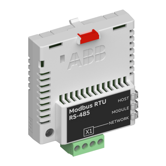
Page 23: Layout Of The Adapter Module
Overview of the RS-485 network and the FSCA-01 module 23 Layout of the adapter module The figure below shows the layout of FSCA-01 adapter module. Description See chapter Lock Mechanical installation Mounting screw Mechanical installation Bus connector X1 Electrical installation... - Page 24 24 Overview of the RS-485 network and the FSCA-01 module...
-
Page 25: Mechanical Installation
See also, the applicable drive hardware manual. Unpacking and examining the delivery 1. Open the option package. 2. Make sure that the package contains: • FSCA-01 RS-485 adapter module • this manual. 3. Make sure that there are no signs of damage. -
Page 26: Installing The Adapter Module
26 Mechanical installation Installing the adapter module WARNING! Obey the safety instructions. See chapter Safety instructions on page 9. If you ignore the safety instructions, injury or death can occur. The adapter module has a specific position in the drive. You can plug and unplug the adapter when the drive is power off and no external 24 voltage supplied to the control board. - Page 27 Mechanical installation 27 2. Put the adapter module carefully into its position on the drive. 3. Push in the lock. 4. Tighten the screw to torque 0.8 N·m using a Torx TX10 screwdriver. Note: A too high torque may break the screws. It is necessary to tighten the screw properly to fulfill the EMC requirements and to ensure the proper operation of the module.
- Page 28 28 Mechanical installation...
-
Page 29: Electrical Installation
Electrical installation 29 Electrical installation What this chapter contains This chapter contains: • general cabling instructions • instructions on connecting the module to the RS-485 network • instructions on switching on the bus termination. Warnings WARNING! Obey the safety instructions. See chapter Safety instructions on page 9. -
Page 30: General Cabling Instructions
30 Electrical installation General cabling instructions • Arrange the bus cables as far away from the motor cables as possible. • Avoid parallel runs. • Use bushings at cable entries. Connecting the module to the RS-485 network Connect the bus cable to connector X1 on the adapter module. The pin allocation of the X1 connector is shown below. -
Page 31: Switching On The Bus Termination
Electrical installation 31 Switching on the bus termination Bus termination is required to prevent signal reflections from the bus cable ends. The adapter module is equipped with internal bus termination, which is configurable with jumper J2 pins. Activate the termination on the devices located at the bus ends and deactivate it on the other devices. - Page 32 32 Electrical installation...
-
Page 33: Start-Up
Start-up 33 Start-up What this chapter contains This chapter contains: • information on configuring the drive for operation with the adapter module • drive-specific instructions and examples on starting up the drive with the adapter module • information on configuring the master station for communication with the adapter module. -
Page 34: Drive Configuration
34 Start-up Drive configuration The following information applies to all drive types compatible with the adapter module, unless otherwise stated. Modbus/RTU connection configuration After the adapter module has been mechanically and electrically installed according to the instructions in chapters Mechanical installation Electrical... -
Page 35: Fsca-01 Configuration Parameters - Group A (Group 1)
Start-up 35 FSCA-01 configuration parameters – group A (group 1) Note: The actual parameter group number depends on the drive type. Group A (group 1) corresponds to: • parameter group 51 in ACS355, ACSM1, ACS530, ACS850 and ACQ810 • parameter group 51 in ACS880 if the adapter is installed as fieldbus adapter A or group 54 if the adapter is installed as fieldbus adapter B. - Page 36 8 data bits Modbus timeout The Modbus/RTU protocol does not specify a timeout mechanism for the application layer. ABB Drives and the FSCA-01 module provide a Modbus timeout method as it may be desired for drive control. The timeout is:...
- Page 37 Start-up 37 Name/Value Description Default OK messages Read-only. Shows the number of valid messages which the drive has received. 0…65535 Number of valid messages CRC errors Read-only. Shows the number of messages with a cyclic redundancy check (CRC) error which the drive has received. If the number is high, check the CRC calculation for possible errors.
- Page 38 38 Start-up Name/Value Description Default Mode 0 Used when access to parameter indexes greater than 99 is not needed. Allows 5-digit addressing used by legacy Modbus masters. 16-bit access: Register address = 100 * parameter group + parameter index (16-bit values, groups 1...199, indexes 1...99).
- Page 39 Start-up 39 Name/Value Description Default 13... Reserved These parameters are not used by the adapter module. Protocol check Read only. Shows whether the parameters of the selected communication protocol have been loaded to the module. - If the value of this parameter corresponds to the setting of par.
- Page 40 40 Start-up Name/Value Description Default Par table ver Read-only. Displays the parameter table revision of the fieldbus adapter module mapping file stored in the memory of the drive. In format xyz, where x = major revision number y = minor revision number z = correction number in format axyz, where a = major revision number...
- Page 41 Start-up 41 Name/Value Description Default FBA comm SW ver Read-only. Displays the common program of the adapter module in format axyz, where: a = major revision number xy = minor revision number z = correction number or letter. Common program version of the adapter module FBA appl SW ver Read-only.
-
Page 42: Fsca-01 Configuration Parameters - Group B (Group 2)
42 Start-up FSCA-01 configuration parameters – group B (group 2) Note: The actual parameter group number depends on the drive type. Group B (group 2) corresponds to: • parameter group 55 in ACS355 • parameter group 53 in ACSM1, ACS530, ACS850 and ACQ810 •... -
Page 43: Fsca-01 Configuration Parameters - Group C (Group 3)
Start-up 43 FSCA-01 configuration parameters – group C (group 3) Note: The actual parameter group number depends on the drive type. Group C (group 3) corresponds to: • parameter group 54 in ACS355 • parameter group 52 in ACSM1, ACS530, ACS850 and ACQ810 •... -
Page 44: Control Locations
44 Start-up Control locations ABB drives can receive control information from multiple sources including digital inputs, analog inputs, the drive control panel and a communication module (for example, the adapter module). ABB drives allow the user to separately determine the source for each type of control information (Start, Stop, Direction, Reference, Fault reset, etc.). -
Page 45: Starting Up Acs355 Drives
2. Enable the communication between the adapter module and the drive by setting parameter 9802 COMM PROT SEL to EXT FBA. 3. Set the FSCA-01 configuration parameters in group 51. • Select the communication protocol with parameter 5125 and profile with parameter 5102. -
Page 46: Parameter Setting Examples - Acs355
Speed and torque control using the ABB Drives - Enhanced communication profile This example shows how to configure a speed and torque control application that uses the ABB Drives - Enhanced profile. In addition, some application-specific data is added to the communication. - Page 47 Start-up 47 Drive parameter Setting for Description ACS355 drives 5102 FB PAR 2 1 (= ABB Selects the ABB Drives - (PROFILE) Enhanced) Enhanced profile. 5103 FB PAR 3 Defines the address of the device. (STATION ID) 5104 FB PAR 4 4 (= 115.2 kbit/s)
- Page 48 48 Start-up Drive parameter Setting for Description ACS355 drives 1102 EXT1/EXT2 SEL 8 = COMM Enables external control location 1/2 selection through the fieldbus. 1103 REF1 SELECT 8 = COMM Selects the fieldbus reference 1 as the source for speed reference. 1106 REF2 SELECT 8 = COMM Selects the fieldbus reference 2 as...
-
Page 49: Starting Up Acsm1 Drives
5. Select application-specific values for parameters 50.04…50.11. Examples of appropriate values are shown in the tables below. 6. Set the FSCA-01 configuration parameters in group 51. • Select the communication protocol with parameter 51.25 and profile with parameter 51.02. -
Page 50: Parameter Setting Examples - Acsm1
Speed and torque control using the ABB Drives - Enhanced communication profile This example shows how to configure a speed and torque control application that uses the ABB Drives - Enhanced profile. In addition, some application-specific data is added to the communication. - Page 51 51.01 FBA TYPE RS-485 COMM Displays the type of the fieldbus adapter module. 51.02 FBA PAR2 1 (= ABB Enhanced) Selects the ABB Drives - (PROFILE) Enhanced profile. 51.03 FBA PAR3 Defines the address of the (STATION ID) device.
- Page 52 53.03 FBA DATA OUT3 2410 Speed reference for jogging function 1 51.27 FBA PAR REFRESH REFRESH Validates the FSCA-01 configuration parameter settings. 10.01 EXT1 START FUNC Selects the fieldbus interface as the source of the start and stop commands for external control location 1.
- Page 53 Start-up 53 Drive parameter Setting for ACSM1 Description drives 34.05 EXT2 CTRL MODE1 Torque Selects torque control as the control mode 1 for external control location 2. 1) Read-only or automatically detected/set 2) Example The start sequence for the parameter example above is given below.
-
Page 54: Starting Up Acs880 Drives
5. Select application-specific values for parameters 50.04…50.11. Examples of appropriate values are shown in the tables below. 6. Set the FSCA-01 configuration parameters in group 51. • Select the communication protocol with parameter 51.25 and profile with parameter 51.02. -
Page 55: Parameter Setting Examples - Acs880
This example shows how to configure a speed control application that uses the ABB Drives - Enhanced profile. The start/stop commands and reference are according to the ABB Drives profile. For more information, see the state machine on page 65. - Page 56 51.01 FBA type 485 = RS-485 Displays the type of the fieldbus adapter module. 51.02 Profile 1 = ABB Enhanced Selects the ABB Drives - Enhanced profile. 51.03 Station ID Defines the address of the device. 51.04 Baud rate 4 = 115.2 kbit/s Selects the baud rate of the link.
- Page 57 53.03 FBA data out3 22.27 Constant speed 2 51.27 FBA par refresh 1 = Configure Validates the FSCA-01 configuration parameter settings. 20.01 Ext1 commands 12 = Fieldbus A Selects the fieldbus A interface as the source of the start and stop commands for external control location 1.
-
Page 58: Configuring The Master Station
58 Start-up Configuring the master station After the adapter module has been initialized by the drive, the master station must be prepared for communication with the module. Refer to the documentation of your Modbus/RTU master for more information. Modbus register maps 02 Profile configuration parameter selects the communication profile and Modbus register map that the adapter module presents... -
Page 59: Communication Profiles
(Control word, Status word, references and actual values) between the master station and the drive. You can configure the adapter module to provide either the ABB Drives profile or one of the two Transparent modes for 16-bit and 32-bit words respectively. For the ABB Drives profile, the adapter module converts the data to the native profile (eg, DCU or FBA). - Page 60 Transparent32 Drive-specific profile (with 32-bit words) To be used if the drive does not support the speed control mode of the DCU communication profile or if the ABB Drives profile does not cover all needed functionality like the position control.
-
Page 61: Abb Drives Communication Profile
The drive states are presented on page 65. Control word contents The table below shows the contents of the Control word for the ABB Drives communication profile. The upper case boldface text refers to the states shown in the state machine on page 65. Name... - Page 62 62 Communication profiles Name Value STATE/Description INHIBIT_ Proceed to OPERATION ENABLED. OPERATION Note: Run enable signal must be active; see drive documentation. If the drive is set to receive the Run enable signal from the fieldbus, this bit activates the signal. Inhibit operation.
-
Page 63: Status Word Contents
Drive-specific (For information, see the drive documentation.) Status word contents The table below shows the contents of the Status word for the ABB Drives communication profile. The upper case boldface text refers to the states shown in the state machine on page 65. - Page 64 64 Communication profiles Name Value STATE/Description ALARM Warning/Alarm No warning/alarm OPERATION. Actual value equals reference SETPOINT (= is within tolerance limits, ie, in speed control, speed error is 10% max. of nominal motor speed). Actual value differs from reference (= is outside tolerance limits.) REMOTE Drive control location: REMOTE (EXT1 or...
-
Page 65: State Machine
Communication profiles 65 State machine The state machine for the ABB Drives communication profile is shown below. SWITCH-ON ABB Drives MAINS OFF INHIBITED (SW Bit6=1) communication Power ON (CW Bit0=0) profile NOT READY TO SWITCH ON (SW Bit0=0) = Control word... -
Page 66: References
ABB drives can receive control information from multiple sources including analog and digital inputs, the drive control panel and a communication module (for example, FSCA-01). To have the drive controlled through the fieldbus, the module must be defined as the source for control information, for example, reference. -
Page 67: Actual Values
Communication profiles 67 Actual values Actual values are 16-bit words containing information on the operation of the drive. The functions to be monitored are selected with a drive parameter. Scaling Actual values are scaled as shown below. Note: The values of REF1 MAX and REF2 MAX are set with drive parameters. - Page 68 68 Communication profiles...
-
Page 69: Communication Protocol
Modbus/RTU is a variant of the Modbus family of simple, vendor neutral communication protocols intended for supervision and control of automation equipment. The FSCA-01 RS-485 adapter module acts as a Modbus/RTU slave with support for ABB Drives and Transparent profiles. The Modbus commands supported are listed in section Function codes on page 70. -
Page 70: Register Addressing
70 Communication protocol Register addressing The address field of Modbus requests for accessing holding registers is 16 bits. This allows the Modbus protocol to support addressing of 65536 holding registers. Historically, Modbus master devices used 5-digit decimal addresses from 40001 to 49999 to represent holding register addresses. - Page 71 Communication protocol 71 Function Name Description code Diagnostics Provides a series of tests for checking the communication between the master and the slave devices, or for checking various internal error conditions within the slave. The following subcodes are supported: 00 Return Query Data: The data passed in the request data field is to be returned in the response.
-
Page 72: Encapsulated Interface Transport / Read Device Identification
72 Communication protocol Function Name Description code Write Multiple Registers Writes the contents of a contiguous block of holding registers in a server device. Read/Write Multiple Writes the contents of a Registers contiguous block of holding registers in a server device, then reads the contents of a contiguous block of holding registers (same or different than... -
Page 73: Exception Codes
Communication protocol 73 Exception codes The adapter module supports the Modbus exception codes shown below. Exception Name Description Code ILLEGAL FUNCTION The function code received in the query is not an allowable action for the server. ILLEGAL DATA The data address received in the ADDRESSS query is to an allowable address for the server. -
Page 74: Abb Drives Profile - Classic
ABB Drives profile - Classic The ABB Drives profile - Classic communication profile provides register mapped access to the control, status, reference and actual values of the ABB Drives profile in the classic format for backward compatibility. 1), 2) Register Address... - Page 75 Communication protocol 75 1), 2) Register Address Register Data (16-bit) (4)20000…(4)29999 Drive Parameter Access (32-bit) (not supported with ACS355) Register Address = (4)20000 + 200 × Group + 2 × Index Example for Drive Parameter 1.27: (4)20000 + 200 × 1 + 2 × 27 = (4)20254 Note: Addressing depends on the address mode selected with parameter 12 in group A (51/151, 54/154).
-
Page 76: Abb Drives Profile - Enhanced
The ABB Drives profile - Enhanced communication profile provides register mapped access to the control, status, reference and actual values of the ABB Drives profile. The mapping of the registers has been enhanced to allow writing of control and reading of status in a single Read/Write Multiple Register request. - Page 77 Communication protocol 77 1), 2) Register Address Register Data (16-bit) (4)00057 DATA IN 4 (4)00058 DATA IN 5 (4)00059 DATA IN 6 (4)00060 DATA IN 7 (4)00061 DATA IN 8 (4)00062 DATA IN 9 (4)00063 DATA IN 10 (4)00064 DATA IN 11 (4)00065 DATA IN 12 (4)00101…(4)09999...
-
Page 78: Transparent 16-Bit
78 Communication protocol Transparent 16-bit The Transparent 16-bit communication profile provides unaltered 16-bit access to the configured drive profile. 1), 2) Register Address Register Data (16-bit) (4)00001 Native Drive Profile Control (4)00002 Native Drive Profile Reference 1 (4)00003 Native Drive Profile Reference 2 (4)00004 DATA OUT 1 (4)00005... -
Page 79: Transparent 32-Bit
Communication protocol 79 1), 2) Register Address Register Data (16-bit) (4)00062 DATA IN 9 (4)00063 DATA IN 10 (4)00064 DATA IN 11 (4)00065 DATA IN 12 (4)00101…(4)09999 Drive Parameter Access (16-bit) Register Address = (4)00000 + 100 × Group + Index Example for Drive Parameter 3.18: (4)00000 + 100 ×... - Page 80 80 Communication protocol 1), 2) Register Address Register Data (16-bit) (4)00003 Native Drive Profile Reference 1 - Least Significant 16-bits (4)00004 Native Drive Profile Reference 1 - Most Significant 16-bits (4)00005 Native Drive Profile Reference 2 - Least Significant 16-bits (4)00006 Native Drive Profile Reference 2 - Most Significant 16-bits...
- Page 81 Communication protocol 81 1), 2) Register Address Register Data (16-bit) (4)00057 DATA IN 1 (4)00058 DATA IN 2 (4)00059 DATA IN 3 (4)00060 DATA IN 4 (4)00061 DATA IN 5 (4)00062 DATA IN 6 (4)00063 DATA IN 7 (4)00064 DATA IN 8 (4)00065 DATA IN 9 (4)00066...
- Page 82 82 Communication protocol...
-
Page 83: Diagnostics
Diagnostics 83 Diagnostics What this chapter contains This chapter explains how to trace faults with the status LEDs on the adapter module. -
Page 84: Led Indications
Configuration error Flashing orange, Internal file system error. The error may alternating with be cleared by cycling drive power. If the the MODULE error persists, contact your local ABB flashing orange representative. Green The device is operating in a normal condition. -
Page 85: Internal Error Code Registers
A Modbus query can fail in many ways in the drive. The Modbus standard does not specify detailed error descriptions. In addition to the standard error codes, the FSCA-01 module provides an internal error register area for more detailed diagnostics. - Page 86 86 Diagnostics Address Registers (16-bit word) (4)00094 Last register that was written successfully (4)00095 Last register that was read successfully Error code Description Situation 0x00 No error Used when a Modbus query was successful 0x02 Low or high limit Change access with a value exceeded outside the value limits 0x03...
-
Page 87: Technical Data
Technical data 87 Technical data What this chapter contains This chapter contains the technical specifications of the adapter module and the RS-485 link. FSCA-01 The figure below shows the enclosure of the adapter module from the front and side. -
Page 88: Rs-485 Link
88 Technical data Mounting Into the option slot of the drive Degree of protection IP20 Ambient conditions The applicable ambient conditions specified for the drive in its manuals are in effect. Indicators Three LEDs (HOST, MODULE, NETWORK) Connectors 20-pin connector to the drive 4-pin detachable screw connector to the bus 6-pin jumper block 2 for bus termination configuration... -
Page 89: Further Information
Address any inquiries about the product to your local ABB representative, quoting the type designation and serial number of the unit in question. A listing of ABB sales, support and service contacts can be found by navigating to abb.com/searchchannels. Product training For information on ABB product training, navigate to new.abb.com/service/training. - Page 90 3AUA0000109533C © Copyright 2019 ABB. All rights reserved. Specifications subject to change without notice.