
Related Manuals for Huawei SMU01A


Summary of Contents for Huawei SMU01A
- Page 1 SMU01A V100R001 User Manual Issue Date 2015-10-08 HUAWEI TECHNOLOGIES CO., LTD.
- Page 2 Notice The purchased products, services and features are stipulated by the contract made between Huawei and the customer. All or part of the products, services and features described in this document may not be within the purchase scope or the usage scope. Unless otherwise specified in the contract, all statements, information, and recommendations in this document are provided "AS IS"...
- Page 3 Provides a tip that may help you solve a problem or save time. Provides additional information to emphasize or supplement important points in the main text. Issue 06 (2015-10-08) Huawei Proprietary and Confidential Copyright © Huawei Technologies Co., Ltd...
- Page 4 Issue 03 (2012-12-05) Port description is modified. Issue 02 (2011-06-12) This issue is the second official release. The SMU01A revision changed to C02, the document revision changed to 02. Issue 01 (2011-04-20) This issue is the first official release. Issue 06 (2015-10-08) Huawei Proprietary and Confidential Copyright ©...
-
Page 5: Table Of Contents
5.6 Opening a .TXT File Exported from the Web UI ................... 38 6 Installation............................ 39 6.1 Safety Precautions ............................39 6.2 Installing the SMU01A ..........................39 6.3 Replacing the SMU01A ..........................40 7 Troubleshooting Methods ......................41 A Acronyms and Abbreviations ....................42... -
Page 6: Smu01A Overview
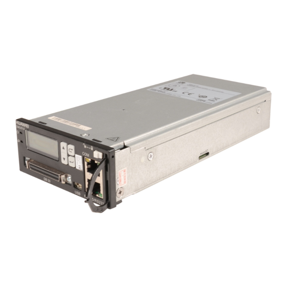
1 SMU01A Overview SMU01A Overview 1.1 Description The SMU01A is an advanced site monitoring unit (SMU) and consists of a shell, an LCD panel, and multiple manufactured boards. It is applicable to the Embedded Telecom Power (ETP) V100R001C02. The SMU01A has the following features: ... - Page 7 SMU01A User Manual 1 SMU01A Overview Figure 1-1 SMU01A in in-band communication Huawei communications equipment RS485 SMU01A RS485/ Sensors Battery Smoke Ambient Door Water Battery cabinet D.G. sensor temperature sensor sensor temperature sensor humidity sensor Figure 1-2 SMU01A in out-of-band communication...
-
Page 8: Performance Specifications
SMU01A User Manual 1 SMU01A Overview 1.3 Performance Specifications Table 1-1 describes performance specifications of the SMU01A, such as its dimensions, weight, and storage environment. Table 1-1 Performance specifications Item Specifications Dimensions (H x W x D) 44.5 mm x 95.5 mm x 208 mm (1.75 in. x 3.76 in. x 8.19 in.) ≤... - Page 9 Resets the smoke sensor remotely. (The smoke sensor can be remotely reset after an alarm is cleared.) Provides eight dry contact outputs. Alarm Reports alarms for SMU01A faults. reporting Reports DC overvoltage alarms. Reports DC undervoltage alarms. Reports alarms for abnormal load currents.
- Page 10 1 SMU01A Overview Category Function Reports alarms for LVD2 disconnection. Reports alarms for overcurrent. Reports alarms for battery losing. PDE Failure PDE Branch Failure PDE Branch Protection Issue 06 (2015-10-08) Huawei Proprietary and Confidential Copyright © Huawei Technologies Co., Ltd...
-
Page 11: Panel And Ports
2 Panel and Ports Panel and Ports SMU01A Panel NOTE All ports in this manual are protected by a security mechanism. Figure 2-1 shows the SMU01A panel. Figure 2-1 SMU01A panel (1) Running status (2) Alarm indicator (3) LCD (4) Four buttons... - Page 12 2 Panel and Ports Table 2-1 Indicator description Name Color Meaning Status Description Running Green Indicates the The SMU01A is faulty or has status running no DC input. indicator status. Blinking at 0.5 The SMU01A runs properly and communicates with the host properly.
- Page 13 SMU01A Sensor signal converter DB50 transfer cable NOTE The DB50 transfer cable and sensor signal converter are extended components of the SMU01A. USB Port The universal serial bus (USB) port is not used in this version. Communications Ports The SMU01A communicates with the host over communications ports. Table 2-3 describes the communications ports on the SMU01A panel.
- Page 14 A secure digital (SD) card is inserted into this port to store a large capacity of data. The SD card port is not used in this version. Issue 06 (2015-10-08) Huawei Proprietary and Confidential Copyright © Huawei Technologies Co., Ltd...
-
Page 15: Lcd Description
3.1 LCD Application This section describes how to select a display language, view active alarms, and set parameters quickly on the LCD. For details about how to use the buttons on the SMU01A panel, see Table 2-2. Selecting a Display Language After the SMU01A is powered on, the screen for selecting a display language is displayed. - Page 16 This section describes how to quickly set the number of battery strings and rated battery capacity on the LCD, as shown in Figure 3-2. The parameter values in Figure 3-2 are for reference only. Issue 06 (2015-10-08) Huawei Proprietary and Confidential Copyright © Huawei Technologies Co., Ltd...
-
Page 17: Menu Hierarchy
001. You can add or delete users, and change the user name and password. 3.2 Menu Hierarchy Figure 3-3 shows the LCD main menu. For details about the parameters, see Table 3-1. Issue 06 (2015-10-08) Huawei Proprietary and Confidential Copyright © Huawei Technologies Co., Ltd... -
Page 18: Lcd Menu
Active alarm Running status Site Summary Auto/Man Ctl System Voltage Total Load Ambient Humi Ambient Temp 1 Ambient Temp 2 PSU Summary Total Current Used Capacity AC Voltage Issue 06 (2015-10-08) Huawei Proprietary and Confidential Copyright © Huawei Technologies Co., Ltd... - Page 19 PDE Summary PDE Number Comm PDE Total Power Total Current Comm Status PDE1 Total Run Time Branch Number Total Power Total Current Branch(1-4) Power Branch(1-4) Current Branch(1-4) Voltage Issue 06 (2015-10-08) Huawei Proprietary and Confidential Copyright © Huawei Technologies Co., Ltd...
- Page 20 AC Under Volt 180 V System AC Type Single Phase Dial-up Network Disable Amb High Temp 40° C Amb Low Temp 0° C Amb High Humi Amb Low Humi Issue 06 (2015-10-08) Huawei Proprietary and Confidential Copyright © Huawei Technologies Co., Ltd...
- Page 21 Cyclic BC Intv 30 Days Cyc BC Duration Battery Test Test End Volt 46.0 V Test End Capa 70.0% Test End Temp 5° C Test End Time 480 Min Issue 06 (2015-10-08) Huawei Proprietary and Confidential Copyright © Huawei Technologies Co., Ltd...
- Page 22 0.8C10 Dis 0.9 H Time 0.9C10 Dis 0.7 H Time 1.0C10 Dis 0.5 H Time Capacity Coeff LVD Setting LVD1 Enabled Disable LVD2 Enabled Enable LVD2Mode By Voltage Issue 06 (2015-10-08) Huawei Proprietary and Confidential Copyright © Huawei Technologies Co., Ltd...
- Page 23 Enable LVD2Mode By Voltage LVD2Voltage 43.2 V LVD2Recon 51.5 V Volt Communication Host CommAddr - Parameter Host Baudrate 9600 bit/s DHCP Disable Phone Number 1 Account 1 Issue 06 (2015-10-08) Huawei Proprietary and Confidential Copyright © Huawei Technologies Co., Ltd...
- Page 24 Set Site Name SMU_SITE Set Batt1 Type Set Batt2 Type LCD Contrast PDE1 Branch1 Current 10 A Limitation Branch2 Current 20 A Limitation Branch3 Current 20 A Issue 06 (2015-10-08) Huawei Proprietary and Confidential Copyright © Huawei Technologies Co., Ltd...
- Page 25 Reset Batt Capa Clear Batt Alarm LVD1 Control LVD2 Control PSU Summary Current Limit DC Voltage Ctrl On/Off Control Reset Clear RectLost Clr Phase Fail PSU1 Reset Issue 06 (2015-10-08) Huawei Proprietary and Confidential Copyright © Huawei Technologies Co., Ltd...
- Page 26 Gateway NOTE The LCD Menu is dynamic changed due to the different configuration, the above table only for reference, the detailed information based on the SMU01A LCD Menu that you used. Issue 06 (2015-10-08) Huawei Proprietary and Confidential Copyright © Huawei Technologies Co., Ltd...
-
Page 27: Web Ui Description
Browser: Internet Explorer 6.0 or later 4.2 Preparations for Login Set the IP address, gateway, and subnet mask of the SMU01A before logging into the web UI. You also need to set the network and Internet Explorer. Issue 06 (2015-10-08) Huawei Proprietary and Confidential Copyright ©... - Page 28 Setting the LAN CAUTION If the SMU01A is connected to a local area network (LAN) and a proxy server has been selected, you need to cancel proxy server setting. If the SMU01A is connected to the Internet but the computer is connected to the LAN, you cannot cancel proxy server setting;...
-
Page 29: Web Ui Overview
To ensure the security of data transmission, the NetEco transmits data after encrypting it over SSL. Enter the IP address of the SMU01A in the Internet Explorer address box and press Enter. A login page is displayed, as shown in Figure 4-3. Set User Name to admin and Password to 001, and then press Login. - Page 30 You can configure the site, PSUs, and batteries on the System Configuration tab page, as shown in Figure 4-5. Figure 4-6 shows the Site Summary page. Figure 4-5 System Configuration tab page Issue 06 (2015-10-08) Huawei Proprietary and Confidential Copyright © Huawei Technologies Co., Ltd...
- Page 31 IP addresses and port number under NetEco. Figure 4-7 shows the Network Configuration tab page. Figure 4-8 shows the expanded Network Configuration tab page. Figure 4-7 Network Configuration tab page Issue 06 (2015-10-08) Huawei Proprietary and Confidential Copyright © Huawei Technologies Co., Ltd...
- Page 32 You can set control parameters for the site, PSUs, batteries, and power distribution unit on the Control tab page, as shown in Figure 4-9. Figure 4-10 shows the Control tab page. Issue 06 (2015-10-08) Huawei Proprietary and Confidential Copyright © Huawei Technologies Co., Ltd...
- Page 33 SMU01A User Manual 4 Web UI Description Figure 4-9 Control tab page Issue 06 (2015-10-08) Huawei Proprietary and Confidential Copyright © Huawei Technologies Co., Ltd...
- Page 34 Figure 4-11. Users are classified into three types: admin, engineer, and operator. Different user types have different operation rights. Only admin users have user management rights. Issue 06 (2015-10-08) Huawei Proprietary and Confidential Copyright © Huawei Technologies Co., Ltd...
- Page 35 4 Web UI Description Figure 4-11 User Management tab page Upgrade Tab Page You can upgrade the SMU01A, PSU, PDE software on the Upgrade tab page, as shown in Figure 4-12. To upgrade SMU01A software, perform the following steps: Step 1 Click Browse to select the software and then click Send.
- Page 36 You can download historical alarms on the History Alarms tab page, as shown in Figure 4-14. To export historical alarms in HTML files, click Export. To clear historical alarms, click Clean. Issue 06 (2015-10-08) Huawei Proprietary and Confidential Copyright © Huawei Technologies Co., Ltd...
- Page 37 On the Site Configure tab page, you can set the system date and time, site and storage batteries, and save, download, and upload configuration files, as shown in Figure 4-16. Issue 06 (2015-10-08) Huawei Proprietary and Confidential Copyright © Huawei Technologies Co., Ltd...
- Page 38 Send to upload the files. Electronic Label Tab Page You can query electronic label information about system components such as the SMU01A, power distribution rack, and PSUs on the Electronic Label tab page. Click Export to export the electronic label information in HTML files.
-
Page 39: Operation Guide
You can set communications addresses of Huawei communications equipment on the LCD or over the web UI. If the SMU01A is connected to an Ethernet over a COM port, you need to set the IP address, subnet mask, and gateway on the LCD based on those assigned by customers and then perform other operations. - Page 40 Figure 5-1 Setting the IP address of the NetEco server Communicating with a Third-Party EMS over SNMP Configure the network over the web UI when the SMU01A communicates with a third-party EMS. After you select the appropriate SNMP version, set the trap address (a maximum of six addresses) and trap port on the Network Configuration tab page.
-
Page 41: Selecting A Display Language
Selecting a Display Language on the LCD You can select a display language when the SMU01A is being powered on or on the LCD. On the LCD, you can choose Settings > System Parameter > LUI Language and select a language. -
Page 42: Setting Battery Parameters
Figure 5-5 Setting battery parameters 5.5 Upgrading Software Remotely The SMU01A software can be upgraded over the web UI or EMS UI. For details about how to upgrade the software remotely on the web UI, see "Upgrade Tab Page."... -
Page 43: Opening A .Txt File Exported From The Web Ui
Step 1 Open a .TXT file. Step 2 Choose File > Open, select the .TXT file that you need to open, set Encoding to Unicode, and then click Open. ----End Issue 06 (2015-10-08) Huawei Proprietary and Confidential Copyright © Huawei Technologies Co., Ltd... -
Page 44: Installation
Step 1 Hold the handle of the SMU01A, and insert the SMU01A into the correct position in the power system. Step 2 Push the SMU01A until its front panel is level with that of the subrack in the power system. Step 3 Push the locking latch on the front panel to the right. -
Page 45: Replacing The Smu01A
SMU01A User Manual 6 Installation 6.3 Replacing the SMU01A To remove the SMU01A, push the locking latch to the left to release the handle and then pull the SMU01A. Issue 06 (2015-10-08) Huawei Proprietary and Confidential Copyright © Huawei Technologies Co., Ltd... -
Page 46: Troubleshooting Methods
SMU01A User Manual 7 Troubleshooting Methods Troubleshooting Methods This section describes how to rectify common faults of the SMU01A. Table 7-1 describes the methods for rectifying the common faults. Table 7-1 Troubleshooting methods Symptom Cause Solution The alarm indicator is red... -
Page 47: A Acronyms And Abbreviations
Fast Ethernet first office application HTTPS Hyper Text Transport Protocol Secure low voltage disconnection liquid crystal display NetEco Network Ecosystem Power supply unit power distribution with electronic switch Issue 06 (2015-10-08) Huawei Proprietary and Confidential Copyright © Huawei Technologies Co., Ltd... - Page 48 SMU01A User Manual A Acronyms and Abbreviations secure digital SNMP Simple Network Management Protocol site monitoring unit universal serial bus Issue 06 (2015-10-08) Huawei Proprietary and Confidential Copyright © Huawei Technologies Co., Ltd...