Table of Contents
Advertisement
SITOP power supply
SITOP PSU100L
Manual
SITOP PSU100L 24V/2.5A
6EP1332-1LB00
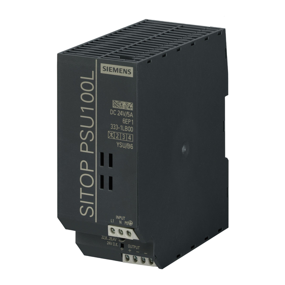
SITOP PSU100L 24V/5A
6EP1333-1LB00
SITOP PSU100L 24V/10A
6EP1334-1LB00
SITOP PSU100L 24V/20A
6EP1336-1LB00
08.2016
C98130-A7603-A1-2-7629
Overview
Safety instructions
Description, device design,
dimension drawing
Mounting/removal
Mounting position, mounting
clearances
Installation
Technical data
Safety, approvals, EMC
Ambient conditions
Applications
Environment
Service & Support
1
2
3
4
5
6
7
8
9
10
11
Advertisement
Table of Contents

Related Manuals for Siemens SITOP PSU100L 6EP1332-1LB00


Summary of Contents for Siemens SITOP PSU100L 6EP1332-1LB00
- Page 1 Overview Safety instructions Description, device design, dimension drawing SITOP power supply Mounting/removal SITOP PSU100L Mounting position, mounting clearances Installation Manual Technical data Safety, approvals, EMC Ambient conditions Applications Environment Service & Support SITOP PSU100L 24V/2.5A 6EP1332-1LB00 SITOP PSU100L 24V/5A 6EP1333-1LB00 SITOP PSU100L 24V/10A 6EP1334-1LB00 SITOP PSU100L 24V/20A...
-
Page 2: C98130-A7603-A1
Note the following: WARNING Siemens products may only be used for the applications described in the catalog and in the relevant technical documentation. If products and components from other manufacturers are used, these must be recommended or approved by Siemens. Proper transport, storage, installation, assembly, commissioning, operation and maintenance are required to ensure that the products operate safely and without any problems. -
Page 3: Overview
Overview Description The 1-phase SITOP PSU100L from the SITOP lite product line is the power supply series to address basic requirements in the industrial environment. It offers all of the important functions at a favorable price – and does not compromise when it comes to quality and reliability. - Page 4 Overview Ordering data The following device options are available: Regulated power supply unit SITOP PSU100L Type Order number Input, 120/230 V AC 6EP1332-1LB00 Output, 24 V DC/2.5 A Input, 120/230 V AC 6EP1333-1LB00 Output, 24 VDC/5 A Input, 120/230 V AC 6EP1334-1LB00 Output, 24 V DC/10 A Input, 120/230 V AC...
-
Page 5: Table Of Contents
Table of contents Overview..............................3 Safety instructions ........................... 7 Description, device design, dimension drawing..................9 Device description ........................9 Connections and terminal designation..................10 Potentiometer .......................... 12 Status displays and signaling ....................13 Voltage selector switch ......................14 Block diagram ......................... 15 Dimensions and weight ...................... - Page 6 Table of contents Safety, approvals, EMC ........................43 Safety ............................. 43 Test voltage ..........................44 Approvals ..........................45 EMC ............................45 Ambient conditions ..........................47 Applications ............................49 Parallel connection to increase power rating ................. 49 Parallel connection for redundancy ..................51 Series connection for increased voltage ................
-
Page 7: Safety Instructions
Safety instructions WARNING Correct handling of the devices When operating electrical devices, it is inevitable that certain components will carry dangerous voltages. Therefore, failure to handle the units properly can result in death or serious physical injury as well as extensive property damage. Only appropriately qualified personnel may work on or in the vicinity of this equipment. - Page 8 Safety instructions SITOP PSU100L Manual, 08.2016, C98130-A7603-A1-2-7629...
-
Page 9: Description, Device Design, Dimension Drawing
Description, device design, dimension drawing Device description SITOP PSU100L is a primary-clocked power supply for connection to a 1-phase AC line supply. An electronically regulated DC voltage that can be set via a potentiometer is available at the output of the device. The output of the device is isolated, no-load proof and short-circuit proof. -
Page 10: Connections And Terminal Designation
Description, device design, dimension drawing 2.2 Connections and terminal designation Connections and terminal designation Note UL requirement: Use suitable copper cables that are designed for operating temperatures of at least 65 °C/75 °C. ① The line input terminals can be used to establish the connection to supply voltage. The ②... - Page 11 Description, device design, dimension drawing 2.2 Connections and terminal designation Do not subject the end stop to higher loads Figure 2-3 Terminal data for 6EP1336-1LB00 SITOP PSU100L Manual, 08.2016, C98130-A7603-A1-2-7629...
-
Page 12: Potentiometer
Description, device design, dimension drawing 2.3 Potentiometer Potentiometer ③ The potentiometer on the front of the device is used to set the output voltage. The output voltage is set to 24 V in the factory, and can be adjusted in the range 22.8 - 26.4 V (for 6EP1336-1LB00 22.8 - 28 V);... -
Page 13: Status Displays And Signaling
Description, device design, dimension drawing 2.4 Status displays and signaling Status displays and signaling 6EP1332-1LB00 (24 V / 2.5 A) 6EP1333-1LB00 (24 V / 5 A) 6EP1334-1LB00 (24 V / 10 A) 6EP1336-1LB00 (24 V/20 A) Operating display LED green for "24 V O.K." Figure 2-5 Operating display and signaling (example 6EP1334-1LB00) Signaling... -
Page 14: Voltage Selector Switch
Description, device design, dimension drawing 2.5 Voltage selector switch Voltage selector switch Selector switch for the input voltage range Figure 2-6 120 V/230 V voltage selector switch (example, 6EP1334-1LB00) The selector switch as delivered (factory setting) is in the 230 V position. It must be moved to the appropriate position for operation in the 120 V range. -
Page 15: Block Diagram
Description, device design, dimension drawing 2.6 Block diagram Block diagram Setting range for 6EP1336-1LB00: 22.6 - 28 V Figure 2-7 Block diagram SITOP PSU100L Manual, 08.2016, C98130-A7603-A1-2-7629... -
Page 16: Dimensions And Weight
Description, device design, dimension drawing 2.7 Dimensions and weight Dimensions and weight Figure 2-8 Dimension drawing 6EP1332-1LB00 Figure 2-9 Dimension drawing 6EP1333-1LB00 SITOP PSU100L Manual, 08.2016, C98130-A7603-A1-2-7629... - Page 17 Description, device design, dimension drawing 2.7 Dimensions and weight Figure 2-10 Dimension drawing 6EP1334-1LB00 Figure 2-11 Dimension drawing 6EP1336-1LB00 6EP1332-1LB00 6EP1333-1LB00 6EP1334-1LB00 6EP1336-1LB00 (24 V/2.5 A) (24 V/5 A) (24 V/10 A) (24 V/20 A) Dimensions 32.5 × 125 × 120.3 50 ×...
- Page 18 Description, device design, dimension drawing 2.7 Dimensions and weight SITOP PSU100L Manual, 08.2016, C98130-A7603-A1-2-7629...
-
Page 19: Mounting/Removal
Mounting/removal WARNING Installing the device in a housing or a control cabinet SITOP PSU100L power supplies are built-in devices. They must be installed in a housing or control cabinet where only qualified personnel have access. The device can be mounted in a control cabinet on standard mounting rails TH35-15/7,5 (EN 60715). - Page 20 Mounting/removal SITOP PSU100L Manual, 08.2016, C98130-A7603-A1-2-7629...
-
Page 21: Mounting Position, Mounting Clearances
Mounting position, mounting clearances Standard mounting position The device is mounted on standard mounting rails according to EN 60715 35×7,5/15. The device must be mounted vertically in such a way that the input terminals and the output terminals are at the bottom to ensure correct cooling. A clearance of at least 50 mm should be maintained above and below the device. - Page 22 Mounting position, mounting clearances 4.1 Standard mounting position Figure 4-3 6EP1334-1LB00 mounting position Figure 4-4 6EP1336-1LB00 mounting position Figure 4-5 Mounting height derating SITOP PSU100L Manual, 08.2016, C98130-A7603-A1-2-7629...
-
Page 23: Other Mounting Positions
Mounting position, mounting clearances 4.2 Other mounting positions Other mounting positions For mounting positions that deviate from the standard mounting position, derating factors (reduction of the output power or the permissible ambient temperature) must be observed in accordance with the following diagrams. Note In the case of mounting positions that deviate from the standard mounting position, reduced mechanical resistance of the devices against vibration and shock must be expected. - Page 24 Mounting position, mounting clearances 4.2 Other mounting positions Figure 4-8 6EP1332-1LB00 mounting position (3) Figure 4-9 6EP1332-1LB00 mounting position (4) Figure 4-10 6EP1332-1LB00 mounting position (5) SITOP PSU100L Manual, 08.2016, C98130-A7603-A1-2-7629...
-
Page 25: 6Ep1333-1Lb00
Mounting position, mounting clearances 4.2 Other mounting positions 4.2.2 6EP1333-1LB00 Figure 4-11 6EP1333-1LB00 mounting position (1) Figure 4-12 6EP1333-1LB00 mounting position (2) Figure 4-13 6EP1333-1LB00 mounting position (3) SITOP PSU100L Manual, 08.2016, C98130-A7603-A1-2-7629... - Page 26 Mounting position, mounting clearances 4.2 Other mounting positions Figure 4-14 6EP1333-1LB00 mounting position (4) Figure 4-15 6EP1333-1LB00 mounting position (5) SITOP PSU100L Manual, 08.2016, C98130-A7603-A1-2-7629...
-
Page 27: 6Ep1334-1Lb00
Mounting position, mounting clearances 4.2 Other mounting positions 4.2.3 6EP1334-1LB00 Figure 4-16 6EP1334-1LB00 mounting position (1) Figure 4-17 6EP1334-1LB00 mounting position (2) Figure 4-18 6EP1334-1LB00 mounting position (3) SITOP PSU100L Manual, 08.2016, C98130-A7603-A1-2-7629... - Page 28 Mounting position, mounting clearances 4.2 Other mounting positions Figure 4-19 6EP1334-1LB00 mounting position (4) Figure 4-20 6EP1334-1LB00 mounting position (5) SITOP PSU100L Manual, 08.2016, C98130-A7603-A1-2-7629...
-
Page 29: 6Ep1336-1Lb00
Mounting position, mounting clearances 4.2 Other mounting positions 4.2.4 6EP1336-1LB00 Figure 4-21 6EP1336-1LB00 mounting position (1) Figure 4-22 6EP1336-1LB00 mounting position (2) Figure 4-23 6EP1336-1LB00 mounting position (3) SITOP PSU100L Manual, 08.2016, C98130-A7603-A1-2-7629... - Page 30 Mounting position, mounting clearances 4.2 Other mounting positions Figure 4-24 6EP1336-1LB00 mounting position (4) Figure 4-25 6EP1336-1LB00 mounting position (5) SITOP PSU100L Manual, 08.2016, C98130-A7603-A1-2-7629...
-
Page 31: Installation
Installation WARNING Hazard due to electric shock Before installation or maintenance work can begin, the system's main switch must be switched off and measures taken to prevent it being switched on again. If this instruction is not observed, touching live parts can result in death or serious injury. Line-side connection SITOP PSU100L power supplies are designed for connection to a 1-phase AC line supply (TN or TT system according to VDE 0100 T 300/IEC 364-3) with a rated voltage of... -
Page 32: Output-Side Connection
Installation 5.2 Output-side connection Protection SITOP PSU100L Required line-side protection 6EP1332-1LB00 (24 V/2.5 A) Miniature circuit breaker (IEC 898), characteristic C, 3 A 6EP1333-1LB00 (24 V/5 A) Miniature circuit breaker (IEC 898), characteristic C, 6 A 6EP1334-1LB00 (24 V/10 A) Miniature circuit breaker (IEC 898), characteristic C, 10 A 6EP1336-1LB00 (24 V/20 A) Miniature circuit breaker (IEC 898), characteristic C, 10 A... -
Page 33: Technical Data
Technical data Note Technical data apply for a rated input voltage, rated load and 25 °C ambient temperature if nothing else is specified. Input 6EP1332-1LB00 6EP1333-1LB00 6EP1334-1LB00 6EP1336-1LB00 (24 V/2.5 A) (24 V/5 A) (24 V/10 A) (24 V/20 A) Input 1-phase, AC Rated voltage U... -
Page 34: Output
Technical data 6.2 Output Figure 6-1 Power failure buffering Output 6EP1332-1LB00 6EP1333-1LB00 6EP1334-1LB00 6EP1336-1LB00 (24 V/2.5 A) (24 V/5 A) (24 V/10 A) (24 V/20 A) Output Regulated, isolated DC voltage Rated voltage U 24 V out rated Total tolerance, static ± Static line regulation, ap- 0.1 % 0.1 %... - Page 35 Technical data 6.2 Output 6EP1332-1LB00 6EP1333-1LB00 6EP1334-1LB00 6EP1336-1LB00 (24 V/2.5 A) (24 V/5 A) (24 V/10 A) (24 V/20 A) Starting delay, max. 1.5 s 1.5 s 1.5 s 1.5 s Start delay, typ. 150 ms 150 ms 1.5 s Voltage rise 500 ms 500 ms...
- Page 36 Technical data 6.2 Output Figure 6-3 Output characteristic 6EP1332-1LB00 Figure 6-4 Output characteristic 6EP1333-1LB00 Figure 6-5 Output characteristic 6EP1334-1LB00 SITOP PSU100L Manual, 08.2016, C98130-A7603-A1-2-7629...
- Page 37 Technical data 6.2 Output Figure 6-6 6EP1336-1LB00 output characteristic The device supplies a constant output voltage until the current limit is reached. In the event of an overload, the output current and the output voltage are reduced. When the output voltage falls below approx.
-
Page 38: Efficiency
Technical data 6.3 Efficiency Efficiency 6EP1332-1LB00 6EP1333-1LB00 6EP1334-1LB00 6EP1336-1LB00 (24 V/2.5 A) (24 V/5 A) (24 V/10 A) (24 V/20 A) Efficiency at U 85 % 86 % 89 % 93 % out rated , approx. out rated Power loss at U 17 W 34 W 33.6 W... - Page 39 Technical data 6.3 Efficiency Figure 6-9 Efficiency 6EP1334-1LB00 Figure 6-10 Efficiency 6EP1336-1LB00 SITOP PSU100L Manual, 08.2016, C98130-A7603-A1-2-7629...
-
Page 40: Closed-Loop Control
Technical data 6.4 Closed-loop control Closed-loop control 6EP1332-1LB00 6EP1333-1LB00 6EP1334-1LB00 6EP1336-1LB00 (24 V/2.5 A) (24 V/5 A) (24 V/10 A) (24 V/20 A) Dyn. line regulation 0.3 % 0.3 % 0.3 % 0.1 % ±15 %), max. in rated Dyn. load regulation : 10/90/10 %), max. -
Page 41: Mechanical System
S7-300 rail mounting Mounting Can be snapped onto standard TH35-15/7,5 (EN 60715) mounting rails Dimension drawing See chapter Dimensions and weight (Page 16) CAD data that can be downloaded from the Internet: 6EP1332-1LB00 (http://www.automation.siemens.com/bilddb/index.aspx?objKey=G_KT01_XX_00677) 6EP1333-1LB00 (http://www.automation.siemens.com/bilddb/index.aspx?objKey=G_KT01_XX_00674) 6EP1334-1LB00 (http://www.automation.siemens.com/bilddb/index.aspx?objKey=G_KT01_XX_00671) 6EP1336-1LB00 (http://www.automation.siemens.com/bilddb/index.aspx?objKey=G_KT01_XX_01216) SITOP PSU100L Manual, 08.2016, C98130-A7603-A1-2-7629... - Page 42 Technical data 6.8 Dimension drawing SITOP PSU100L Manual, 08.2016, C98130-A7603-A1-2-7629...
-
Page 43: Safety, Approvals, Emc
Safety, approvals, EMC Safety 6EP1332-1LB00 6EP1333-1LB00 6EP1334-1LB00 6EP1336-1LB00 (24 V/2.5 A) (24 V/5 A) (24 V/10 A) (24 V/20 A) Primary/secondary galvanic isolation Galvanic isolation SELV output voltage U acc. to EN 60950-1 and EN 50178 Protection class Class I Degree of protection IP20 (EN 60529) -
Page 44: Test Voltage
Safety, approvals, EMC 7.2 Test voltage Test voltage Figure 7-1 Test voltage without auxiliary contact diagram Only the manufacturer can perform the type test and production test; users can also perform the field test. Preconditions for performing the field test: Tests (A) &... -
Page 45: Approvals
Safety, approvals, EMC 7.3 Approvals Approvals 6EP1332-1LB00 (24 V / 2.5 A) 6EP1333-1LB00 (24 V / 5 A) 6EP1334-1LB00 (24 V / 10 A) 6EP1336-1LB00 (24 V / 20 A) CE marking UL/CSA approval UL/cUL (CSA) approval cULus-listed (UL 508, CSA 22.2 No. 107.1), File E197259 CB approval 6EP1332-1LB00 (24 V/2.5 A) 6EP1333-1LB00 (24 V/5 A) - Page 46 Safety, approvals, EMC 7.4 EMC SITOP PSU100L Manual, 08.2016, C98130-A7603-A1-2-7629...
-
Page 47: Ambient Conditions
Ambient conditions 6EP1332-1LB00 (24 V/2.5 A) 6EP1336-1LB00 (24 V/20 A) 6EP1333-1LB00 (24 V/5 A) 6EP1334-1LB00 (24 V/10 A) Ambient temperature 0 … 60 °C for natural convection (self 0 … 70 °C for natural convection (self convection) convection) Tested according to: EN 60068-2-1 cold •... - Page 48 Ambient conditions 6EP1332-1LB00 (24 V/2.5 A) 6EP1336-1LB00 (24 V/20 A) 6EP1333-1LB00 (24 V/5 A) 6EP1334-1LB00 (24 V/10 A) Damaging gases Tested according to: EN 60068-2-42 sulfur dioxide • EN 60068-2-43 hydrogen sulfide • Atmospheric pressure Operation: 1080 - 795 hPa (-1000 - 2000 m) •...
-
Page 49: Applications
Applications Parallel connection to increase power rating To increase the power rating, SITOP PSU100L power supplies of the same type can be directly connected in parallel. The following must be observed: ● The cables connected to each power supply at terminals "+" and "-" must have identical lengths and the same cable cross-sections (or the same impedance) up to a common external connection point (terminal strip) if possible. - Page 50 Applications 9.1 Parallel connection to increase power rating NOTICE Protective circuit for the parallel connection of more than two power supplies For connection of more than two power supplies in parallel, additional measures must be taken to prevent high backward feeding currents in the event of a secondary device fault. For this purpose, a suitable protective circuit (e.g.
-
Page 51: Parallel Connection For Redundancy
Figure 9-2 Redundant configuration with two power supplies and SITOP PSE202U redundancy module You can find additional information at: SITOP PSE202U manual (http://support.automation.siemens.com/WW/view/en/42248598) SITOP PSU100L Manual, 08.2016, C98130-A7603-A1-2-7629... -
Page 52: Series Connection For Increased Voltage
Applications 9.3 Series connection for increased voltage Series connection for increased voltage To achieve an output voltage of 48 V DC, two 24 V SITOP PSU100L power supplies of the same type can be connected in series. In this case, connect the "-" terminal of the first power supply to the "+"... -
Page 53: Protection Against Short-Time Voltage Dips
24 V power supply output SITOP PSE201U manual (http://support.automation.siemens.com/WW/view/en/41129219)). The buffer time is 200 ms at 40 A up to 1.6 s for a load current of 5 A. This time can be increased a multiple number of times by connecting buffer modules in parallel;... - Page 54 Applications 9.4 Protection against short-time voltage dips SITOP PSU100L Manual, 08.2016, C98130-A7603-A1-2-7629...
-
Page 55: Environment
Environment The devices are in conformance with RoHS. As a rule, only non-silicon precipitating materials are used. Disposal guidelines Packaging and packaging aids can and should always be recycled. The product itself may not be disposed of as domestic refuse. SITOP PSU100L Manual, 08.2016, C98130-A7603-A1-2-7629... - Page 56 Environment SITOP PSU100L Manual, 08.2016, C98130-A7603-A1-2-7629...
-
Page 57: Service & Support
● Phone: + 49 (0) 911 895 7222 ● E-Mail (mailto:support.automation@siemens.com) ● Internet: Online support request form (http://www.siemens.de/automation/support-request) Technical documentation on the Internet Operating instructions and manuals for SITOP are available in the Internet: Operating instructions/manuals (http://www.siemens.de/sitop/manuals) SITOP power supply homepage General news about our power supplies is available in the Internet at the SITOP homepage: SITOP (http://www.siemens.de/sitop) - Page 58 Service & Support Contact persons If you have any questions regarding the use of our products, then contact the Siemens contact person in your regional Siemens sales office. You can find these addresses as follows: ● On the Internet (http://www.siemens.de/automation/partner) ●...