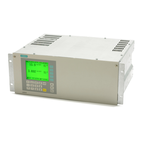
Siemens LDS 6 Operating Instructions Manual
In-situ laser continuous gas analyzer
Hide thumbs
Also See for LDS 6:
- Operating instructions manual (84 pages) ,
- Compact operating instructions (70 pages) ,
- Product information (30 pages)

Related Manuals for Siemens LDS 6


Summary of Contents for Siemens LDS 6
- Page 1 LDS 6 In-situ Laser Gas Analyzer Operating Instructions 01/2009 • Continuous Gas Analysis...
- Page 3 General Information Technical Information Installation Guidelines Continuous Gas Analysis Operation In Situ Laser Gas Analyzers LDS 6 Alarms Maintenance and Service Operating Instructions Spare Parts List Technical Data Dimensional Drawings ESD guidelines List of Abbreviations 01/2009 A5E00295894-05...
-
Page 4: Operation
Note the following: WARNING Siemens products may only be used for the applications described in the catalog and in the relevant technical documentation. If products and components from other manufacturers are used, these must be recommended or approved by Siemens. Proper transport, storage, installation, assembly, commissioning, operation and maintenance are required to ensure that the products operate safely and without any problems. -
Page 5: Table Of Contents
3.3.1 Power Supply Connections......................29 3.3.2 Hybrid Cable Connection ......................31 3.3.3 Signal Cable Connection ......................32 3.3.4 Pin Assignment of LDS 6 ......................34 Three Channel System ........................35 3.4.1 External Power Supply.........................35 3.4.2 Three Channel Hybrid Cable Connection ..................36 Flange Installation Requirements ....................37 Installation of Flanges ........................37... - Page 6 Central Unit ..........................83 Hybrid and Sensor Cables ......................87 Purging ............................88 Dimensional Drawings ..........................89 ESD guidelines ............................93 ESD guidelines..........................93 List of Abbreviations ..........................95 List of Abbreviations........................95 Index................................ 99 LDS 6 Operating Instructions, 01/2009, A5E00295894-05...
-
Page 7: General Information
Siemens regional office. Note In particular, before using the device for new research and development applications, we recommend that you first contact your Siemens representative or our application department to discuss the application in question. LDS 6... -
Page 8: Special Information And Warnings
All obligations on the part of Siemens AG are contained in the respective sales contract, which also contains the complete and solely applicable liability provisions. The provisions defined in the sales contract for the responsibility for defects are neither extended nor limited by the remarks in this document. -
Page 9: Technical Information
General Description Overview LDS 6 is a diode laser gas analyzer with a measuring principle based on the specific light absorption of different gas components. LDS 6 is suitable for fast and non-contact measurement of gas concentrations or temperatures in process or flue gases. One or two signals from up to three measuring points are processed simultaneously by one central analyzer unit. -
Page 10: Alarms
2.1 General Description Benefits The in-situ gas analyzer LDS 6 is characterized by a high availability and unique analytical selectivity, and by a broad scope of suitable applications. LDS 6 enables the measurement of one or two gas components or – if desired – the gas temperature directly in the process: ●... - Page 11 Technical Information 2.1 General Description Application The LDS 6 laser gas analyzer is suitable for a wide range of applications. The most common of them are: ● Process optimization ● Continuous emission monitoring for all kinds of fuels (oil, gas, coal, and others) ●...
- Page 12 For new analyzer orders, the NH , NH O and H O kits named "Version 2" must be ordered. In case of doubt or for already installed analyzers, please contact Siemens for spotting the correct kit version. LDS 6 Operating Instructions, 01/2009, A5E00295894-05...
-
Page 13: Design
2.2 Design Design The gas analyzer LDS 6 consists of a central unit and up to three in-situ sensors. The connection between the central unit and the sensors is established by a so-called hybrid cable, which contains optical fibers and copper wires. An additional cable connects the transmitter and receiver parts of the cross-duct sensor. - Page 14 ● LED background illumination of the display with energy-saving function ● Easy-to-clean membrane touch pad with softkeys ● Menu-driven operation for parameterization and diagnostics ● Operation support in plain text Figure 2-3 LDS 6 central unit, membrane keyboard and graphic display LDS 6 Operating Instructions, 01/2009, A5E00295894-05...
- Page 15 Windows 95/98/ME or Windows NT/2000/XP. It is also possible to connect the LDS 6 via modem to the public telephone net. In that case an LDS 6 LAN modem kit is required. Any external connection requires the optional software LDSComm (LDS Communication Client) to be installed on the remote computer.
- Page 16 ● In-situ cross-duct sensors, configured as transmitter and receiver unit, connected via sensor cable ● Connection to the LDS 6 central unit by a so-called hybrid cable, max. length 700 m ● Stainless steel, partially painted ● IP65 degree of protection for sensor ●...
- Page 17 For further information regarding the ATEX option please refer to the separate ATEX manual for LDS 6. Parts in contact with the process gases The sensors normally do not come into contact with the process gas, since purging with a gaseous media is applied at the process side.
- Page 18 ● Additionally for the hybrid cable: – Single-mode fiber-optic cable, configured double-sided with E2000 connectors for transmission of laser light ● Rugged cable sheath for mounting in open cable ducts or ductworks ● Sheath material: oil-resistant polyurethane LDS 6 Operating Instructions, 01/2009, A5E00295894-05...
-
Page 19: Operating Principle
2.3 Operating Principle Operating Principle LDS 6 is a gas analyzer employing single-line molecular absorption spectroscopy. A diode laser emits a beam of near-infrared light, which passes through the process gas and is detected by a receiver unit. The wavelength of the laser diode output is tuned to a gas- specific absorption line. -
Page 20: Configuration Examples
Figure 2-7 Typical transmitted light setup of LDS 6, in-situ A feature of the standard applications defined in the ordering data of the LDS 6 is that the typical process conditions are well-known and documented, and that the guaranteed measuring properties can be proven by reference installations. If you cannot find your application among the standard applications, please contact Siemens. -
Page 21: Measurement Principle
Measurement Principle Mode of operation The operation of LDS 6 is based on the fact that light propagating through a gas mixture will be absorbed according to Beer-Lambert's law at certain narrow wavelength bands. This is where the gases possess molecular transitions forming narrow absorption lines. - Page 22 In this case, the ratio of the absorbance of two characteristic lines of the same molecule measured at the same time in the same volume gives the actual temperature in the process gas. Typical measurable gases for LDS 6 are: ) for low and high pressure ● Oxygen (O ●...
- Page 23 The optical damping increases at longer path lengths. Smaller particles also have a large influence on the optical damping. With a combination of high dust load, long path length and small particle size, the technical support at Siemens should be consulted. Temperature The temperature influence on the absorption line strength is compensated by a correction factor determined during calibration.
- Page 24 2.5 Measurement Principle Pressure The gas pressure can affect the line shape of the molecular absorption line. LDS 6 uses a special algorithm to adapt the line shape. Additionally, an external pressure signal can be fed to the instrument to provide complete compensation for the pressure influence including the density effect.
-
Page 25: Installation Guidelines
The device can be used in an industrial environment. Laser Safety All lasers used by LDS 6 are of class 1. The emitted laser light is in most cases invisible (near infrared) and the intensity is low enough so that the unprotected eye is not damaged under normal circumstances. - Page 26 The distance between the central unit and the sensors can be several hundred meters. The LDS 6 system is available in an Ex version and is then delivered with an approval for use in hazardous environments. The ATEX certificate is a system certificate and is only valid if LDS 6 is installed according to the instructions given in the certificate.
- Page 27 An absolute condition for the approval is that the equipment is set up according to the drawing, ADM 3040 3050, please refer to the separate ATEX manual for LDS 6. The protection is as follows:...
-
Page 28: General Installation Information
General Installation Information Mounting Conditions The central unit LDS 6 should be placed on a location which is dust-free and as free as possible from vibrations. The distance between the central unit and the measurement point, i.e. the sensor, may not exceed 1000 meters (3,280 ft) for the non ATEX version and 600 m (1,970 ft) for the ATEX version. -
Page 29: Electrical Connections
There are three kinds of cables used for the LDS 6 depending on the application: ● Hybrid cables for all types of systems except oxygen. These are installed between the LDS 6 and the transmitter sensor. - Page 30 ● A circuit-breaker shall be part of the installation. It must be provided in the immediate vicinity of the analyzer (see rating plate for loading capacity). It must also be labeled to correlate with the instrument. LDS 6 Operating Instructions, 01/2009, A5E00295894-05...
-
Page 31: Hybrid Cable Connection
Figure 3-1 LDS 6 cable connections (here only channel 3 is connected) WARNING Keep the fiber end protected, by the protective tube, until it is time for connection. Only authorized personnel are entitled to remove the protective tube and proceed with the connecting operation. -
Page 32: Signal Cable Connection
"Pin assignments for I/O connectors". The conductor cross-section should be 0.5 mm . It is recommended to use cables of type JE-LiYCY... BD. The cable length of the analog outputs depends on the load. LDS 6 Operating Instructions, 01/2009, A5E00295894-05... - Page 33 ● In the case of analyzers with two or three channels, the analyzer sections are connected in parallel and the signal cables of each channel are independent. Only the power plug is common to all channels. LDS 6 Operating Instructions, 01/2009, A5E00295894-05...
-
Page 34: Pin Assignment Of Lds 6
Installation Guidelines 3.3 Electrical Connections 3.3.4 Pin Assignment of LDS 6 The signal connection is carried out by using two DSUB connectors for each channel – one 15 pins and one 25 pins. Connector SUB-D 15F Analog outputs: Component 2... -
Page 35: Three Channel System
3.4.1 External Power Supply The three channel version of LDS 6 uses an external power supply for the sensors. The setup at the sensor site is the same as for one and two channel systems. Also the ATEX version of the three channel LDS 6 is using an external power supply leaving the sensors unaffected when a third channel is added. -
Page 36: Three Channel Hybrid Cable Connection
ATEX. + – + – + – Figure 3-5 Connection of electrical cables for a 3 channel unit CAUTION The instrument is not designed to feed 3 sensors using the internal power supply. LDS 6 Operating Instructions, 01/2009, A5E00295894-05... -
Page 37: Flange Installation Requirements
Installation of Flanges When welding the flange tubes it is recommended to have the Flange Alignment Kit. The Flange Alignment Kit from Siemens consists of a light source, two flanges, an aiming tool and a battery charger for the light source. - Page 38 It is also important that the sensor flanges are oriented in such a way that the spring loaded bolts are located in the lower section of the flange. LDS 6 Operating Instructions, 01/2009, A5E00295894-05...
- Page 39 If long purging tubes will be used, a greater effort should be made to align the flanges perfectly. Depending on the diameter and length of the stubs the possibility to align the sensors is more restricted when long purging tubes are used. LDS 6 Operating Instructions, 01/2009, A5E00295894-05...
-
Page 41: Operation
LDS 6 is established, the system is ready to be used. The functions in the LDS 6 are controlled through a keypad on the front of the panel. A 5" LCD screen is used to present the measurement values as well as the instrument’s interface - the MMI. - Page 42 Soft key Possible adaptive meanings: Selection of item in menu tree Selection of function Switch function ON/OFF Component selection LDS 6 Operating Instructions, 01/2009, A5E00295894-05...
- Page 43 Switching function (OFF status, also status display in the status line). Entry into a subsequent menu. Triggering of a function. Measuring mode: analyzer is coded. Service mode: signals are activated according to functions 71 and 77. LDS 6 Operating Instructions, 01/2009, A5E00295894-05...
-
Page 44: Input Sequence Of Data
4.2 Input Sequence of Data Input Sequence of Data The figure "Input sequence interacting with LDS 6" below shows the input sequence of LDS 6. The circled numbers marking certain steps in the input sequence can also be found in the text following the figure. - Page 45 ( ). A soft key ① is assigned to this specific component and it is called by pressing it. Figure 4-2 Input sequence interacting with LDS 6 Entry into Main Menu for a The appearance of the screen menu varies depending on the number of channels and the 3-Channel System number of measured components.
- Page 46 For a channel with two components on a three-channel instrument you must first press the soft key next to the desired channel and thereafter (in the next window) press the soft key next to the desired component. LDS 6 Operating Instructions, 01/2009, A5E00295894-05...
-
Page 47: Analyzer Functions
● Channel-specific functions act on all components of the corresponding channel, independently from the analyzer component through which the function was called. ● Component-specific functions act on a single component, and can only be called through this. LDS 6 Operating Instructions, 01/2009, A5E00295894-05... - Page 48 1* Analyzer-specific functions. 2* Channel-specific functions. 3* Component-specific functions. Some of the existing functions in other Siemens analyzers are not present in LDS 6, thus some function numbers may be missing in the preceding table. LDS 6 Operating Instructions, 01/2009, A5E00295894-05...
-
Page 49: Analyzer Status
● OS Version: Version number of the Windows CE operative system running in the analyzer. ● CE Software: Version number of the LDS 6-specific software. ● CE Driver Software: Version number of the driver software. ● Analyzer uC Drv.Software: Version number of the software running on the main micro controller. - Page 50 End value 0.00 100.0 mg/Nm This value corresponds to a 4mA current on the analog output. End Value This value corresponds to a 20mA current on the analog output. See also Alarms (Page 65) LDS 6 Operating Instructions, 01/2009, A5E00295894-05...
-
Page 51: Calibration
4.3 Analyzer Functions 4.3.3 Calibration The LDS 6 is calibrated when delivered and does not normally require on site recalibration. Please consult Siemens support if recalibration is needed. CAUTION Never use functions 20 and 21 without having contacted Siemens service staff first. -
Page 52: Measuring Ranges
50 Response Time You can use this function to set various time constants to reduce or suppress noise in the measured signal. 50 Response Time Ch1 NH [5.000] Seconds Actual Measured Value: 63.28 mg/Nm LDS 6 Operating Instructions, 01/2009, A5E00295894-05... - Page 53 Analog output connected to memory (see also function 77). LIM: Limit Upward or downward violation of limit (see also function 51). CTRL: Function Control Start-up mode - Service mode. TR: Transmission Upward or downward violation of transmission limit (see also function 52). LDS 6 Operating Instructions, 01/2009, A5E00295894-05...
- Page 54 The set data are imported when you press the third soft key ("Set Clock"). The data then appear Actual Date Actual Time as an active display at the bottom of the screen. 01-04-2004 14:44 Note Date and time must be reset in case of a power failure. LDS 6 Operating Instructions, 01/2009, A5E00295894-05...
-
Page 55: Configuration
0. This analog output value depends on the adjusted measuring range. If negative measured values have an unfavorable effect on further processing, activate this function. The correct measured value is still output in the display. LDS 6 Operating Instructions, 01/2009, A5E00295894-05... - Page 56 Up to four relays can be configured in one menu. Switching to further menus - and thus to further B2 Ext. Fault Prs. relays - is always carried out by pressing the fifth (last) soft key ("...Continue"). B3 Ext. Fault Purging B4 Ext. Maint.Req. Temp..Continue LDS 6 Operating Instructions, 01/2009, A5E00295894-05...
- Page 57 You can use this function to set communication parameters. This function should only be accessed by service personnel. 73 Communication Ch1 NH IP Address Type :Static: Static IP Address :123.456.789.012: Static Subnet Mask :255.255.255. Static Gateway :123.456.789.012: LDSComm Port Number :5100: LDS 6 Operating Instructions, 01/2009, A5E00295894-05...
- Page 58 You can use this function to erase the working area data and the user data on the EEPROM. 75 Erase Section Ch1 NH The factory data can never be erased. Erase Work Section Erase User Section LDS 6 Operating Instructions, 01/2009, A5E00295894-05...
- Page 59 Use soft key 1 to switch between the different modes. When an alarm occurs and the analog output is set to the latest measured value or 3/1 mA, the display of the concentration value in the measuring screen will be suppressed. LDS 6 Operating Instructions, 01/2009, A5E00295894-05...
- Page 60 After leaving function 80, the relays reassume their former status, prior to selection of the relay and binary test. The column "Binary" shows the current status of the binary inputs in this display. LDS 6 Operating Instructions, 01/2009, A5E00295894-05...
- Page 61 • Correction for temperature using a manual temperature value; Mode: Manual • Correction for temperature using the internally calculated process temperature. Measuring Range: This is only possible if the LDS 6 is set up to measure the temperature of the [0.00 ]- 400.0 °C measuring point.
- Page 62 You can use this function to set the length of the measuring path for the specific channel. Please refer to the sensor manual for more information on measuring the path length. 85 Path Length Ch1 NH [1.000] m LDS 6 Operating Instructions, 01/2009, A5E00295894-05...
- Page 63 LDS 6 and applications where water vapor is set manually. If this function is Dry Gas available in the current LDS 6, it can be activated in the adjacent display, otherwise it is not possible to access function 87.
-
Page 64: Watch Dog
4.4 Watch Dog Watch Dog In the unlikely event that the software in LDS 6 should crash it will reboot with the help of a watch dog. The instrument will be down for approximately 3 minutes if this should happen and then measure normally again. -
Page 65: Alarms
Alarms Alarm Response LDS 6 is able to recognize and alarm for irregularities in its functions. There are five types of alarms that can be triggered depending on the nature of the error: ● Maintenance request alarm ● Faults alarm ●... - Page 66 The analog output can be set to the last measured value or to 3 mA when an alarm occurs (function 77). This response signal is only possible for "Fault alarm", "Transmission alarm", "Transmission pending" and "Function control alarm". See also Configuration (Page 55) LDS 6 Operating Instructions, 01/2009, A5E00295894-05...
-
Page 67: Maintenance Request Alarm
External maintenance Maintenance request from outside. Check external equipment. request Set clock LDS 6 has been switched off. Set date and time. Ambient Analyzer Ambient temperature or pressure is beyond limits Make sure that the ambient specified in technical data. -
Page 68: Faults Alarm
Electronics failure in data acquisition unit. Contact service. CAN Analyzer Electronics failure in internal communication. Contact service. CAN Channel Electronics failure in internal communication. Contact service. Data Flow Analyzer Electronics failure in internal communication. Contact service. LDS 6 Operating Instructions, 01/2009, A5E00295894-05... -
Page 69: Transmission Alarm
Possible Causes ● Start-up procedure is active. ● Analyzer is de-coded. ● Analyzer is communicating with external service software. ● Analyzer is shutting down. ● Analyzer is saving data to EEProm or Flash memory. LDS 6 Operating Instructions, 01/2009, A5E00295894-05... -
Page 71: Maintenance And Service
Maintenance and Service General about Maintenance and Service During normal use, the central unit LDS 6 requires no service. The sensor with its optical surfaces will need regular maintenance. Depending on application and purging method, the interval of maintenance may vary from 1 to 12 months. -
Page 72: Calibration Verification
Calibration Verification For ammonia (NH ) a calibration check of LDS 6 analyzer can be done using a reference cell arrangement containing a mixture of the measurement gas and nitrogen. The unit should be used in conjunction with the 2 meter hybrid cable that is delivered with each calibration verification kit. -
Page 73: Reconfiguration Of Temperature Compensation
4. Press MEAS to return to measurement screen. Press MEAS again to loose privileges. 5. The procedure has to be repeated for other channels. It is not necessary to repeat it for more than one component per channel since it is a channel specific function. LDS 6 Operating Instructions, 01/2009, A5E00295894-05... -
Page 74: Reconfiguration Of Pressure Compensation
4. Press MEAS to return to measurement screen. Press MEAS again to loose privileges. 5. The procedure has to be repeated for other channels. It is not necessary to repeat it for more than one component per channel since it is a channel specific function. LDS 6 Operating Instructions, 01/2009, A5E00295894-05... -
Page 75: Reconfiguration Of The Path Length
3. Press MEAS to return to measurement screen. Press MEAS again to loose privileges. 4. The procedure has to be repeated for other channels. It is not necessary to repeat the procedure for more than one component per channel since this function is a channel- specific function. LDS 6 Operating Instructions, 01/2009, A5E00295894-05... -
Page 77: Spare Parts List
To avoid degraded performance, do not use a spare part with a lower revision number to replace a detector with higher revision number. Figure 7-1 Labeling on the detector unit See also Spare Parts Lists (Page 79) LDS 6 Operating Instructions, 01/2009, A5E00295894-05... -
Page 78: Central Unit Labels
Central Unit Labels Starting February 2009 all version 1 units with MLFB number 7MB6121- (Made in France) are labelled 'E04'. Former version 1 units with MLFB number 7MB6121- (Made in France) are labeled "E01": LDS 6 Central Unit 7MB6121-0CA10-0XX1-Z +A10+B20 N1S1000001... -
Page 79: Spare Parts Lists
LDS 6, Fuse for central unit 100 - 240 V, T2.5L250V A5E00854185 LDS 6, 3 Channel external power supply A5E00854188 LDS 6, Fuse for external power supply 100 - 240 V, T1.25L250V A5E00854190 LDS 6, D-sub 15pin with cable entry A5E00338618... - Page 80 CD 6C and FT 6, Sensor electronic lppm H O (Version 1) A5E00854159 CD 6C and FT 6, Sensor electronic lppm H O NEL (Version 2) A5E01090420 FT 6, Sensor FT 6 electronics A5E00338540 LDS 6 Operating Instructions, 01/2009, A5E00295894-05...
-
Page 81: Ordering Instructions
Spare Parts List 7.3 Ordering Instructions Please note that three of the LDS 6 sensor electronic spare parts are version-dependent. (The PCBs are not affected but detector electronics are different). Table 7- 6 Spare parts ATEX Product description Order no. -
Page 83: Technical Data
The maximum applicable measuring ranges can be found in the table of standard combinations. These can only be applied if the individual process conditions allow. We recom mend to contact our Technical Support for checking the applicability. LDS 6 Operating Instructions, 01/2009, A5E00295894-05... - Page 84 Class 1, safe to the eye Certificates CE marking, TÜV, MCERTS Table 8- 4 Design Design, enclosure Degree of protection IP20 to EN 60529 Dimensions 177 x 440 x 380 mm Weight Approx. 13 kg Mounting horizontal LDS 6 Operating Instructions, 01/2009, A5E00295894-05...
- Page 85 0.095 ... 0.14 kPa - all other gases except O /low pressure 0.095 ... 0.105 kPa Power supply changes < 1 %/30 V Tilting < 1 % for non-horizontal mounting of the central unit < 15° LDS 6 Operating Instructions, 01/2009, A5E00295894-05...
- Page 86 5 ... 45 °C (41 ... 113 °F) - during transportation and storage -40 ... +70 °C (-40 ... +158 °F) Atmospheric pressure 80 ... 110 kPa Humidity < 85 % RH, above dew point LDS 6 Operating Instructions, 01/2009, A5E00295894-05...
-
Page 87: Hybrid And Sensor Cables
Maximum tensile strength 500 N Minimum bending radius 10 cm Table 8- 11 Climatic conditions Climatic conditions Ambient temperature -40 ... +80 °C during operation Rel. humidity < 95 % rel. humidity, above dew point LDS 6 Operating Instructions, 01/2009, A5E00295894-05... -
Page 88: Purging
Table 8- 14 Steam purging Steam purging Steam conditioning Overheated Maximum temperature 240 °C Minimum pressure > 400 kPa Maximum pressure 1 600 kPa, refers to a volume flow of approx. 1 100 l/min LDS 6 Operating Instructions, 01/2009, A5E00295894-05... -
Page 89: Dimensional Drawings
Dimensional Drawings Central unit The central unit will fit in a standard 19" rack. The dimensions are shown below. LDS 6 Figure 9-1 Dimensional drawings of the central unit – LDS 6 LDS 6 Operating Instructions, 01/2009, A5E00295894-05... - Page 90 Dimensional Drawings Connections Figure 9-2 LDS 6, three-channel 19" central unit, optical and electrical connections LDS 6 Operating Instructions, 01/2009, A5E00295894-05...
- Page 91 Relay 4 The relay is de-energized in the shown contact position Relay 3 Relay 2 Relay 1 Contact loading max. 24 V/1 A, AC/DC Figure 9-3 Pin assignment of the LDS 6 central unit LDS 6 Operating Instructions, 01/2009, A5E00295894-05...
-
Page 93: Esd Guidelines
Anyone who is not connected to the electrical potential of their surroundings can be electrostatically charged. The figure below shows the maximum electrostatic voltage which may build up on a person coming into contact with the materials indicated. These values correspond to IEC 801-2 specifications. LDS 6 Operating Instructions, 01/2009, A5E00295894-05... - Page 94 In this way, the discharged energy can not affect the sensitive devices. Discharge your body before you start taking any measurements on a module. Do so by touching grounded metallic parts. Always use grounded measuring instruments. LDS 6 Operating Instructions, 01/2009, A5E00295894-05...
-
Page 95: B List Of Abbreviations
Electromagnetic compatibility Electrostatic Discharge European Union Energy Exchange FPGA Field-programmable Gate Array Water Hydrogen chloride Hydrogen fluoride Hectopascal Height unit for computer housings, 1 HU ≙ 1¾" ≙ 44.45 mm Kelvin Kilohertz kΩ Kiloohms Kilopascal LDS 6 Operating Instructions, 01/2009, A5E00295894-05... - Page 96 Megapascal mΩ Milliohms MΩ Megaohms NAMUR Standards working committee for measuring and control technology in the chemical industry Ammonia (dry) Standard Cubic meter Oxygen Process Automation Personal Computer Printed Circuit Board Process Device Manager LDS 6 Operating Instructions, 01/2009, A5E00295894-05...
- Page 97 Sub-Miniature A, a coaxial connector type Short Wave Fibre (for oxygen analyzers) TCP/IP Transmission Control Protocol/Internet Protocol; a reference model for communication on the Internet Microcontroller Volts Vol % Volume percent Δ Difference (delta) Ω Ohms LDS 6 Operating Instructions, 01/2009, A5E00295894-05...
-
Page 99: Index
Inputs and outputs, 55 Cross-duct sensor Laser diode spectrometer Design, 16 Functional principle, 19 Logbook, 50, 65 Dimensional drawings, 89 Display and control panel Maintenance, 71 Design, 14 Measurement Functions, 41 Influencing variables, 23 Measuring ranges, 52 LDS 6 Operating Instructions, 01/2009, A5E00295894-05... - Page 100 Analyzer functions, 41 Functional principle, 21 Overview, 9 Parameters, 52 Safety Information Electrical safety, 25 Explosion Protection, 26 Heat Safety, 26 Laser Safety, 25 Pressure Safety, 26 Service, 71 Spare parts, 77 Technical specifications, 83 LDS 6 Operating Instructions, 01/2009, A5E00295894-05...
- Page 102 Siemens AG Änderungen vorbehalten A5E00295894 Industry Automation (IA) A5E00295894-05 Sensors and Communication © Siemens AG 2009 Process Analytics 76181 KARLSRUHE A5E00295894 DEUTSCHLAND www.siemens.com/processautomation 4 019169 134279...