Table of Contents
Advertisement
Quick Links
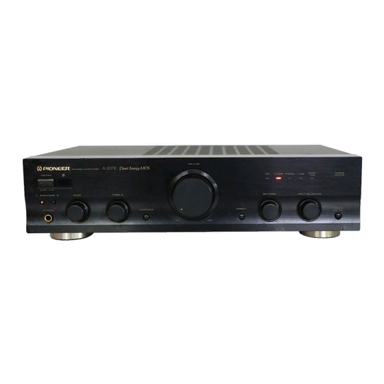
STEREO AMPLIFIER
A-207
THIS MANUAL IS APPLICABLE TO THE FOLLOWING MODEL(S) AND TYPE(S).
Model
Type
A-207
MLXJ
SDXJ
CONTENTS
1. SAFETY INFORMATION ...................................... 2
2. EXPLODED VIEWS AND PARTS LIST ................ 3
3. SCHEMATIC DIAGRAM ....................................... 6
4. PCB CONNECTION DIAGRAM .......................... 14
5. PCB PARTS LIST ............................................... 22
6. ADJUSTMENT .................................................... 25
PIONEER ELECTRONIC CORPORATION
PIONEER ELECTRONICS SERVICE, INC. P.O. Box 1760, Long Beach, CA 90801-1760, U.S.A.
PIONEER ELECTRONIC (EUROPE) N.V. Haven 1087, Keetberglaan 1, 9120 Melsele, Belgium
PIONEER ELECTRONICS ASIACENTRE PTE. LTD. 501 Orchard Road, #10-00 Lane Crawford Place, Singapore 0923
PIONEER ELECTRONIC CORPORATION 1998
z¿<?≥ Direct Energy MOS
STEREO AMPLIFIER
POWER
-
-
OFF
ON
A SPEAKERS B
BASS
PHONES
-
+
-
Power Requirement
AC220 - 230V
AC110V/120 -127V/220V/240V
4-1, Meguro 1-Chome, Meguro-ku, Tokyo 153-8654, Japan
VOLUME
TAPE 1
TAPE 2
CD
TUNER
PHONO
LINE
/MD
MONITOR
TREBLE
BALANCE
INPUT SELECTOR
LOUDNESS
DIRECT
TAPE 2
MONITOR
+
MIN
MAX
L
R
The voltage can be converted by the
following method.
-------
With the voltage selector
7. GENERAL INFORMATION ................................ 26
7.1 IC ................................................................. 26
7.2 DISASSEMBLY ........................................... 27
7.3 BLOCK DIAGRAM ....................................... 28
T - ZZE APR. 1998 Printed in Japan
ORDER NO.
RRV1935
Advertisement
Table of Contents

Related Manuals for Pioneer A-207 MLXJ


Summary of Contents for Pioneer A-207 MLXJ
-
Page 1: Table Of Contents
PIONEER ELECTRONICS SERVICE, INC. P.O. Box 1760, Long Beach, CA 90801-1760, U.S.A. PIONEER ELECTRONIC (EUROPE) N.V. Haven 1087, Keetberglaan 1, 9120 Melsele, Belgium PIONEER ELECTRONICS ASIACENTRE PTE. LTD. 501 Orchard Road, #10-00 Lane Crawford Place, Singapore 0923 PIONEER ELECTRONIC CORPORATION 1998... -
Page 2: Safety Information
The use of a substitute replacement component which does Leakage 0.5mA current Device not have the same safety characteristics as the PIONEER tester under recommended replacement one, shown in the parts list in test this Service Manual, may create shock, fire, or other hazards. -
Page 3: Exploded Views And Parts List
A-207 2. EXPLODED VIEWS AND PARTS LIST • NOTES: Parts marked by "NSP" are generally unavailable because they are not in our Master Spare Parts List. • mark found on some component parts indicates the importance of the safety factor of the part. Therefore, when replacing, be sure to use parts of identical designation. - Page 4 A-207 2.2 EXTERIOR SDXJ Types Only SDXJ Types Only...
- Page 5 Screw (4 × 10) ABA7047 Fuse (FU2, FU3 : 2A) See Contrast table(2) ABN-065 LED Lens A AAK7537 PCB Support AEC7006 PIONEER Badge PAM1755 • • • • • • • • • • PCB Holder AEC7057 Foot REC1263 Cord Clamp F...
-
Page 6: Schematic Diagram
A-207 3. SCHEMATIC DIAGRAM 3.1 OVERALL CONNECTION DIAGRAM HEAD PHONE ASSY AWX7114 FRONT R ASSY AWX7121 AF ASSY AWX7116 VOLUME ASSY AWX7112... - Page 7 A-207 Note : When ordering service parts, be sure to refer to "EXPLODED VIEWS and PARTS LIST" or "PCB PARTS LIST". FRONT L ASSY AWX7122 1602 POWER CORD MLXJ type SDXJ type SDXJ type MLXJ type SDXJ type POWER TRANSFORMER AC PRIMARY ASSY AWX7113(MLXJ) AWX7115(SDXJ)
- Page 8 A-207 3.2 VOLUME AND HEAD PHONE ASSEMBLIES HEAD PHONE ASSY AWX7114 J551A : AUDIO SIGNAL ROUTE VOLUME ASSY AWX7112 CN203...
- Page 9 A-207 3.3 AC PRIMARY ASSY • NOTE FOR FUSE REPLACEMENT FOR CONTINUED PROTECTION AGAINST RISK OF FIRE. CAUTION - REPLACE WITH SAME TYPE AND RATINGS ONLY. AC PRIMARY ASSY AWX7113(MLXJ) AWX7115(SDXJ) SDXJ type REK1023 : MLXJ type T1.25AL250V REK1030 : SDXJ type REK1023 POWER T6.3AL250V...
- Page 10 A-207 3.4 AF ASSY IDLE ADJ. (L CH) IDLE ADJ. (R CH) CN501...
- Page 11 A-207 : AUDIO SIGNAL ROUTE CAUTION : FOR CONTINUED PROTECTION AGAINST RISK OF FIRE. REPLACE ONLY WITH SAME TYPE NO. 491001 MFD, BY , BA : CEBA LITTELFUSE INK. FOR IC454(AEK7009). AF ASSY AWX7116 J551 CN601...
- Page 12 A-207 3.5 FRONT L AND FRONT R ASSEMBLIES FRONT L ASSY AWX7122 FRONT L ASSY S702 : LOUDNESS S703 : SPEAKER A S704 : SPEAKER B...
- Page 13 A-207 FRONT R ASSY AWX7121 INPUT SELECTOR FRONT R ASSY S601 : INPUT SELECTOR TUNER PHONE LINE TAPE1/MD S602 : DIRECT S603 : TAPE2 MONITOR...
-
Page 14: Pcb Connection Diagram
A-207 4. PCB CONNECTION DIAGRAM 4.1 VOLUME ASSY NOTE FOR PCB DIAGRAMS : 1. Part numbers in PCB diagrams match those in the schematic 3. The parts mounted on this PCB include all necessary parts for diagrams. several destinations. 2. A comparison between the main parts of PCB and schematic For further information for respective destinations, be sure to diagrams is shown below. - Page 15 A-207 4.2 HEADPHONE AND AC PRIMARY ASSEMBLIES HEADPHONE ASSY HEADPHONE ASSY (ANP7232-A) (ANP7232-A) J551A SIDE A SIDE B AC PRIMARY ASSY POWER TRANSFORMER VOLTAGE SELECTOR (SDXJ type only) SIDE A POWER CORD (ANP7232-A)
- Page 16 A-207 4.3 AF ASSY AF ASSY POWER TRANSFORMER...
- Page 17 A-207 SIDE A Q153 Q341 IC101 IC451-IC453 CN601 Q333-Q336 Q324,Q326 VR302 Q452 IC301 CN501 Q451 VR301 Q323,Q325 IC454 J551 (ANP7232-A)
- Page 18 A-207 AF ASSY...
- Page 19 A-207 SIDE B Q151 IC151 Q152 Q338,Q337 Q340,Q339 Q102 Q101 Q104 Q103 Q332 Q328,Q327 Q318,Q330 Q322,Q320 Q316,Q314 Q312,Q310 Q304,Q303 Q311,Q309 Q315,Q313 Q321,Q319 Q317,Q329 Q331,Q343 (ANP7232-A)
- Page 20 A-207 4.4 FRONT L ASSY FRONT L ASSY J603A CN502 J602 VR751 VR752 Q707 Q708 (ANP7231-A) SIDE A FRONT L ASSY Q704,Q705 Q702,Q703 Q701,IC751 (ANP7231-A) SIDE B...
- Page 21 A-207 4.5 FRONT R ASSY FRONT R ASSY IC601 VR601 (ANP7231-A) CN202 J602A SIDE A FRONT R ASSY Q601-Q606 Q614-Q616 Q608-Q613 (ANP7231-A) SIDE B...
-
Page 22: Pcb Parts List
A-207 5. PCB PARTS LIST NOTES : ÷ Parts marked by “ NSP ” are generally unavailable because they are not in our Master Spare Parts List. ÷ The mark found on some component parts indicates the importance of the safety factor of the part. Therefore, when replacing, be sure to use parts of identical designation. - Page 23 A-207 7 PARTS LIST FOR A-207/MLXJ Mark No. Description Part No. Mark No. Description Part No. IC301 UPC4570C VOLUME ASSY IC151 UPC4570G2 Q311, Q312, Q329, Q330 2SA1162 Q313, Q314, Q321, Q322 2SA1255 SEMICONDUCTORS Q452 2SA1837 Q513, Q514 2SK246 Q501–Q510 2SK303 Q309, Q310, Q327, Q328 2SC2712 Q511...
- Page 24 A-207 Mark No. Description Part No. Mark No. Description Part No. D608–D612, D615, D617–D620 1SS355 C301, C302, C305, C306 CEBA100M50 D607 SLP6118C51H C307, C308 CEBA221M25 D601–D606 SLP9118C51H C321–C324 CFTYA224J50 C173 CFTYA564J50 SWITCHES AND RELAYS C330, C332 CKCYB331K2H S602, S603 ASG1034 C165, C166 CKSQYB222K50 S601...
-
Page 25: Adjustment
A-207 6. ADJUSTMENT 6.1 IDLE CURRENT ADJUSTMENT ¶ CAUTION : Heatsinks’ (Q323–Q326) DC level is equal to +B or -B. Don’t touch them or you will be electricary chocked. 1. Connect the measuring instrument as Fig.6-1. (R373 or R374) 2. Turn the POWER switch to ON. 3. -
Page 26: General Information
A-207 7. GENERAL INFORMATION 7.1 IC 7 PD5443A (FRONT R ASSY : IC601) • The information shown in the list is basic information and ¶ ¶ ¶ ¶ ¶ REMOTE CONTROL AMP MICROCOMPUTER may not correspond exactly to that shown in the schematic ¶... -
Page 27: Disassembly
A-207 7.2 DISASSEMBLY ×2 ×2 Front Panel Diagnose the AF Assy. ∗ : Be careful not to injure ×2 the Front Panel. ×5 Rear Panel Chassis Unhook lead wires. Rear Panel Service Chassis ×3 Screw for Rear Panel ×2 PCB Support ×3 Cutting Pliers... -
Page 28: Block Diagram
A-207 7.3 BLOCK DIAGRAM... -
Page 29: Panel Facilities And Specifications
A-207 8. PANEL FACILITIES AND SPECIFICATIONS 8.1 PANEL FACILITIES... - Page 30 A-207...
- Page 31 A-207 8.2 SPECIFICATIONS...