Table of Contents
Advertisement
Quick Links
See also:
Manual
S7-200 SMART
SIMATIC
S7
S7-200 SMART
System Manual
09/2015
A5E03822230-AC
___________________
Preface
___________________
Product overview
___________________
Getting started
___________________
Installation
___________________
PLC concepts
___________________
Programming concepts
___________________
PLC device configuration
___________________
Program instructions
___________________
Communication
___________________
Libraries
___________________
Debugging and
troubleshooting
___________________
PID loops and tuning
___________________
Open loop motion control
___________________
Technical specifications
___________________
Calculating a power budget
___________________
Error codes
___________________
Special memory (SM) and
system symbol names
___________________
References
___________________
Ordering information
1
2
3
4
5
6
7
8
9
10
11
12
A
B
C
D
E
F
Advertisement
Table of Contents
Troubleshooting

Related Manuals for Siemens Simatic S7 Series


Summary of Contents for Siemens Simatic S7 Series
- Page 1 ___________________ S7-200 SMART Preface ___________________ Product overview ___________________ Getting started ___________________ SIMATIC Installation ___________________ PLC concepts ___________________ S7-200 SMART Programming concepts ___________________ PLC device configuration ___________________ Program instructions System Manual ___________________ Communication ___________________ Libraries ___________________ Debugging and troubleshooting ___________________ PID loops and tuning ___________________ Open loop motion control ___________________...
- Page 2 Note the following: WARNING Siemens products may only be used for the applications described in the catalog and in the relevant technical documentation. If products and components from other manufacturers are used, these must be recommended or approved by Siemens. Proper transport, storage, installation, assembly, commissioning, operation and maintenance are required to ensure that the products operate safely and without any problems.
-
Page 3: Preface
Siemens products that you are using, they can provide the fastest and most efficient answers to any problems you might encounter. - Page 4 Siemens recommends strongly that you regularly check for product updates. For the secure operation of Siemens products and solutions, it is necessary to take suitable preventive action (e.g. cell protection concept) and integrate each component into a holistic, state-of-the-art industrial security concept.
-
Page 5: Table Of Contents
Table of contents Preface ..............................3 Product overview ............................. 17 S7-200 SMART CPU ......................18 S7-200 SMART expansion modules ..................20 HMI devices for S7-200 SMART ..................... 21 Communications options ......................22 Programming software ......................23 New features ........................... 24 Getting started ............................ - Page 6 Table of contents PLC concepts ............................55 Execution of the control logic ....................55 4.1.1 Reading the inputs and writing to the outputs ................ 57 4.1.2 Immediately reading or writing the I/O ................... 57 4.1.3 Executing the user program ....................58 Accessing data ........................
- Page 7 Table of contents PLC device configuration ........................115 Configuring the operation of the PLC system ............... 115 6.1.1 System block ......................... 115 6.1.2 Configuring communication ....................117 6.1.3 Configuring the digital inputs ....................119 6.1.4 Configuring the digital outputs ....................121 6.1.5 Configuring the retentive ranges ...................
- Page 8 Table of contents 7.5.3 Number value to ASCII string conversion ................208 7.5.4 ASCII sub-string to number value conversion ..............212 7.5.5 Encode and decode ......................215 Counters ..........................216 7.6.1 Counter instructions ......................216 7.6.2 High-speed counter instructions ..................220 7.6.3 Noise reduction for high-speed inputs .................
- Page 9 Table of contents 7.14.2 Shift register bit ........................317 7.15 String ............................. 320 7.15.1 String (Get length, copy, and concatenate) ................320 7.15.2 Copy substring from string ....................322 7.15.3 Find string and first character within string ................323 7.16 Table .............................
- Page 10 Table of contents RS485 ..........................395 8.6.1 PPI protocol .......................... 395 8.6.2 Baud rate and network address ................... 396 8.6.2.1 Definition of baud rate and network address ............... 396 8.6.2.2 Setting the baud rate and network address for the S7-200 SMART CPU ......397 8.6.3 Sample RS485 network configurations ................
- Page 11 Table of contents 9.3.3.4 Modbus slave execution error codes ..................448 9.3.4 Modbus master example program ..................448 9.3.5 Modbus advanced user information ..................450 Debugging and troubleshooting ......................453 10.1 Debugging your program ...................... 453 10.1.1 Bookmark functions ......................453 10.1.2 Cross reference table ......................
- Page 12 Table of contents 12.6.7 AXISx_LDOFF subroutine ....................514 12.6.8 AXISx_LDPOS subroutine ....................515 12.6.9 AXISx_SRATE subroutine ....................516 12.6.10 AXISx_DIS subroutine ......................517 12.6.11 AXISx_CFG subroutine ......................518 12.6.12 AXISx_CACHE subroutine ....................519 12.6.13 AXISx_RDPOS subroutine ....................520 12.6.14 AXISx_ABSPOS subroutine ....................521 12.7 Using the AXISx_ABSPOS subroutine to read the absolute position from a SINAMICS servo drive ..........................
- Page 13 Table of contents A.2.3.3 CPU ST40, SR40 and CR40 wiring diagrams ..............590 A.2.4 CPU ST60, CPU SR60, and CPU CR60 ................593 A.2.4.1 General specifications and features ..................593 A.2.4.2 Digital inputs and outputs ..................... 596 A.2.4.3 CPU ST60, SR60 and CR60 wiring diagrams ..............599 A.2.5 Wiring diagrams for sink and source input, and relay output ..........
- Page 14 Table of contents Special memory (SM) and system symbol names ................. 665 SM (Special Memory) overview ................... 665 SMB0: System status ......................667 SMB1: Instruction execution status..................668 SMB2: Freeport receive character ..................669 SMB3: Freeport character error ................... 669 SMB4: Interrupt queue overflow, run-time program error, interrupts enabled, freeport transmitter idle, and value forced ..................
- Page 15 Table of contents References ............................693 Often-used special memory bits ................... 693 Interrupt events in priority order .................... 694 High-speed counter summary ....................695 Instructions ..........................696 Memory ranges and features ....................703 Ordering information ..........................705 CPU modules ........................705 Expansion modules (EMs) and signal boards (SBs) ............
- Page 16 Table of contents S7-200 SMART System Manual, 09/2015, A5E03822230-AC...
-
Page 17: Product Overview
Product overview The S7-200 SMART series of micro-programmable logic controllers (Micro PLCs) can control a wide variety of devices to support your automation needs. The CPU monitors inputs and changes outputs as controlled by the user program, which can include Boolean logic, counting, timing, complex math operations, and communications with other intelligent devices. -
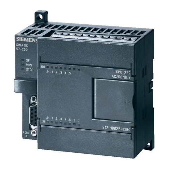
Page 18: S7-200 Smart Cpu
Product overview 1.1 S7-200 SMART CPU S7-200 SMART CPU The CPU combines a microprocessor, an integrated power supply, input circuits, and output circuits in a compact housing to create a powerful Micro PLC. After you have downloaded your program, the CPU contains the logic required to monitor and control the input and output devices in your application. - Page 19 Product overview 1.1 S7-200 SMART CPU Table 1- 2 Compact non-expandable CPUs Features CPU CR40 CPU CR60 Dimensions: W x H x D (mm) 125 x 100 x 81 175 x 100 x 81 User memory Program 12 Kbytes 12 Kbytes User data 8 Kbytes 8 Kbytes...
-
Page 20: S7-200 Smart Expansion Modules
Product overview 1.2 S7-200 SMART expansion modules Refer to the technical specifications (Page 565) for the power requirements of the CPU and the expansion modules. Use the worksheets in Appendix B, Calculating a power budget (Page 656) to calculate your power budget. S7-200 SMART expansion modules To better solve your application requirements, the S7-200 SMART family includes a wide variety of expansion modules, signal boards, and a communications module. -
Page 21: Hmi Devices For S7-200 Smart
TD400C. To start the Text Display wizard, select the "Text Display" command from the "Tools" menu. The SIMATIC Text Display (TD) User Manual can be downloaded from the Siemens customer support web site. S7-200 SMART... -
Page 22: Communications Options
Product overview 1.4 Communications options Communications options The S7-200 SMART offers several types of communication between CPUs, programming devices, and HMIs: ● Ethernet: – Exchange of data from the programming device to the CPU – Exchange of data between HMIs and the CPU –... -
Page 23: Programming Software
Installing STEP 7-Micro/WIN SMART Insert the STEP 7-Micro/WIN SMART CD into the CD-ROM drive of your computer or contact your Siemens distributor or sales office to download STEP7-Micro/WIN SMART from the customer support web site (Page 3). Installation starts automatically and prompts you through the installation process. -
Page 24: New Features
Product overview 1.6 New features New features STEP 7-Micro/WIN SMART V2.1 and the S7-200 SMART V2.1 CPUs introduce the following new features: ● New modules: – EM DP01: intelligent expansion module that supports MPI protocol and PROFIBUS DP V0, V1 as a slave –... -
Page 25: Getting Started
Getting started STEP 7-Micro/WIN SMART makes it easy for you to program your CPU. In just a few short steps using a simple example, you can learn how to create a user program that you can download and run on your CPU. All you need for this example is an Ethernet cable, a CPU, and a programming device running the STEP 7-Micro/WIN SMART programming software. -
Page 26: Configuring The Cpu For Communication
Getting started 2.1 Connecting to the CPU Connect the CPU to a power source. The following figure shows the wiring connections for either a DC or an AC model of the CPU. DC installation AC installation 2.1.1 Configuring the CPU for communication 2.1.1.1 Overview A CPU can communicate with a... -
Page 27: Establishing The Hardware Communication Connection
Getting started 2.1 Connecting to the CPU 2.1.1.2 Establishing the hardware communication connection The Ethernet interfaces establish the physical connections between a programming device and a CPU. Since Auto-Cross-Over functionality is built into the CPU, either a standard or crossover Ethernet cable can be used for the interface. An Ethernet switch is not required to connect a programming device directly to a CPU. - Page 28 Getting started 2.1 Connecting to the CPU For "Found CPUs" (CPUs located on your local network), use the "Communications dialog" to connect with your CPU: Select TCP/IP for your network interface card. • Click the "Find CPUs" button to display all •...
-
Page 29: Creating The Sample Program
Getting started 2.2 Creating the sample program Note The CPU list will show all of the CPUs regardless of Ethernet network class and subnet. To make a connection to your CPU, your network interface card (NIC) and the CPU must be on the same class of network and on the same subnet. -
Page 30: Network 1: Starting The Timer
Getting started 2.2 Creating the sample program Notice the project tree and the pro- gram editor. You use the project tree to insert instructions into the networks of the program editor by dragging and dropping the instructions from the "Instructions" portion of the Project tree to the networks. -
Page 31: Network 2: Turning The Output On
Getting started 2.2 Creating the sample program To enter the timer instruction for T33: 1. Double-click the "Timers" icon to display the timer instructions. 2. Select the "TON" (on-delay timer) instruction. 3. Hold down the left mouse button and drag the timer onto the first network. 4. -
Page 32: Network 3: Resetting The Timer
Getting started 2.2 Creating the sample program To enter the instruction for turning on output M10.0: 1. Double-click the Bit Logic icon to display the bit logic instructions and select the output coil. 2. Hold down the left mouse button and drag the coil onto the second network. 3. -
Page 33: Setting The Cpu Type And Version For Your Project
Getting started 2.2 Creating the sample program 2.2.4 Setting the CPU type and version for your project Configure your project for the CPU and version matching your physical CPU. If the project is not configured for the correct CPU and CPU version, then the download could fail or the program may not run. -
Page 34: Saving The Sample Project
Getting started 2.2 Creating the sample program 2.2.5 Saving the sample project Saving the sample project After entering the three networks of instructions, you have finished entering the program. When you save the program, you create a project that includes the CPU type and other parameters. -
Page 35: Downloading The Sample Program
Getting started 2.3 Downloading the sample program Downloading the sample program To download all project compo- nents, click the "Download" button from the "Transfer" area of the File or PLC menu ribbon strip, or alternatively press the shortcut key combination "CTRL+D". Click the Download dialog "Down- load"... -
Page 36: Changing The Operating Mode Of The Cpu
Getting started 2.4 Changing the operating mode of the CPU Changing the operating mode of the CPU The CPU has two modes of operation: STOP mode and RUN mode. The status LEDs on the front of the CPU indicates the current mode of operation. In STOP mode, the CPU is not executing the program, and you can download program blocks. -
Page 37: Installation
Installation Guidelines for installing S7-200 SMART devices The S7-200 SMART equipment is designed to be easy to install. You can install the S7-200 SMART either on a panel or on a standard DIN rail, and you can orient the S7-200 SMART either horizontally or vertically. The small size of the S7-200 SMART allows you to make efficient use of space. - Page 38 Installation 3.1 Guidelines for installing S7-200 SMART devices Provide adequate clearance for cooling and wiring S7-200 SMART devices are designed for natural convection cooling. For proper cooling, you must provide a clearance of at least 25 mm above and below the devices. Also, allow at least 25 mm of depth between the front of the modules and the inside of the enclosure.
-
Page 39: Power Budget
Installation 3.2 Power budget Power budget Your CPU has an internal power supply that provides power for the CPU, the expansion modules, signal boards, and other 24 V DC user power requirements. Use the following information as a guide for determining how much power (or current) the CPU can provide for your configuration. - Page 40 Installation 3.2 Power budget for a non-isolated analog input. All non-isolated M terminals must connect to the same external reference potential. WARNING Avoiding unwanted current flow Connecting non-isolated M terminals to different reference potentials will cause unintended current flows that may cause damage or unpredictable operation in the PLC and any connected equipment.
-
Page 41: Installation And Removal Procedures
Installation 3.3 Installation and removal procedures Installation and removal procedures 3.3.1 Mounting dimensions for the S7-200 SMART devices The CPU and expansion modules include mounting holes to facilitate installation on panels. S7-200 SMART module Width A (mm) Width B (mm) CPU SR20 and CPU ST20 CPU SR30 and CPU ST30 CPU CR40, CPU SR40, and CPU ST40... -
Page 42: Installing And Removing The Cpu
Installation 3.3 Installation and removal procedures 3.3.2 Installing and removing the CPU The CPU can be easily installed on a standard DIN rail or on a panel. DIN rail clips are provided to secure the device on the DIN rail. The clips also snap into an extended position to provide a screw mounting position for panel-mounting the unit. - Page 43 Installation 3.3 Installation and removal procedures Always ensure that whenever you replace or install a device, you use the correct module or equivalent device. WARNING Module replacement If you install an incorrect module, the program in the CPU could function unpredictably. Failure to replace a device with the same model, orientation, or order could result in death or serious injury to personnel, and/or damage to equipment.
- Page 44 Installation 3.3 Installation and removal procedures Table 3- 1 Installing a CPU on a DIN rail Task Procedure Follow the steps below to install a CPU on a DIN rail. 1. Secure the rail to the mounting panel every 75 mm. 2.
-
Page 45: Installing And Removing An Expansion Module
Installation 3.3 Installation and removal procedures 3.3.3 Installing and removing an expansion module Table 3- 3 Installing an expansion module Task Procedure Follow the steps below to install an expansion module: 1. Ensure that the CPU and all S7-200 SMART equipment are disconnected from electrical power. -
Page 46: Installing And Removing A Signal Board Or Battery Board
Installation 3.3 Installation and removal procedures Table 3- 4 Removing an expansion module Task Procedure Follow the steps below to remove an expansion module: 1. Ensure that the CPU and all S7-200 SMART equipment are disconnected from electrical power. 2. Remove the I/O connectors and wiring from the expansion module. 3. - Page 47 Installation 3.3 Installation and removal procedures Table 3- 6 Removing a signal board or battery board Task Procedure Follow the steps below to remove a signal board or battery board 1. Ensure that the CPU and all S7-200 SMART equipment are disconnected from electri- cal power.
-
Page 48: Removing And Reinstalling The Terminal Block Connector
Installation 3.3 Installation and removal procedures 3.3.5 Removing and reinstalling the terminal block connector The S7-200 SMART modules have removable connectors to make connecting the wiring easy. Table 3- 7 Removing the connector Task Procedure Prepare the system for terminal block removal by removing the power from the CPU and opening the cover above the connector. -
Page 49: Wiring Guidelines
Installation 3.4 Wiring guidelines Wiring guidelines Proper grounding and wiring of all electrical equipment is important to help ensure the optimum operation of your system and to provide additional electrical noise protection for your application and the PLC. Refer to the technical specifications (Page 565) for the wiring diagrams. - Page 50 Installation 3.4 Wiring guidelines Isolation guidelines The AC power supply boundaries and I/O boundaries to AC circuits have been designed and approved to provide safe separation between AC line voltages and low voltage circuits. These boundaries include double or reinforced insulation, or basic plus supplementary insulation, according to various standards.
- Page 51 Siemens recommends that the wire insulation is removed from the wire approximately 6 mm to ensure a proper connection. To avoid damaging the connector, be careful that you do not over-tighten the screws.
- Page 52 Installation 3.4 Wiring guidelines Guidelines for inductive loads You should equip inductive loads with suppression circuits to limit voltage rise when the control output turns off. Suppression circuits protect your outputs from premature failure due to the high voltages associated with turning off inductive loads. In addition, suppression circuits limit the electrical noise generated when switching inductive loads.
- Page 53 Installation 3.4 Wiring guidelines WARNING Correct placement of external resistor/capacitor noise suppression circuit When relay expansion modules are used to switch AC inductive loads, you must place the external resistor/capacitor noise suppression circuit across the AC load to prevent unexpected machine or process operation. Unexpected machine or process operation could result in death or severe personal injury.
- Page 54 Installation 3.4 Wiring guidelines S7-200 SMART System Manual, 09/2015, A5E03822230-AC...
-
Page 55: Plc Concepts
PLC concepts The basic function of the CPU is to monitor field inputs and, based on your control logic, turn on or off field output devices. This chapter explains the concepts used to execute your program, the various types of memory used, and how that memory is retained. Execution of the control logic The CPU continuously cycles through the control logic in your program, reading and writing data. - Page 56 PLC concepts 4.1 Execution of the control logic Tasks in a scan cycle The CPU executes a series of tasks repetitively. This cyclical execution of tasks is called the scan cycle. The execution of the user program is dependent upon whether the CPU is in STOP mode or in RUN mode.
-
Page 57: Reading The Inputs And Writing To The Outputs
PLC concepts 4.1 Execution of the control logic 4.1.1 Reading the inputs and writing to the outputs Reading the inputs Digital inputs: Each scan cycle begins by reading the current value of the digital inputs and then writing these values to the process image input register. Analog inputs: The CPU does not read the analog input values as part of the normal scan cycle. -
Page 58: Executing The User Program
PLC concepts 4.1 Execution of the control logic 4.1.3 Executing the user program During the execution phase of the scan cycle, the CPU executes your main program, starting with the first instruction and proceeding to the last instruction. The immediate I/O instructions give you immediate access to inputs and outputs during the execution of either the main program or an interrupt routine. - Page 59 PLC concepts 4.1 Execution of the control logic Figure 4-1 Typical scan flow S7-200 SMART System Manual, 09/2015, A5E03822230-AC...
-
Page 60: Accessing Data
PLC concepts 4.2 Accessing data Accessing data The CPU stores information in different memory locations that have unique addresses. You can explicitly identify the memory address that you want to access. This allows your program to have direct access to the information. To access a bit in a memory area, you specify the address, which includes the memory area identifier, the byte address, and the bit number (which is also called "byte.bit"... -
Page 61: Accessing Memory Areas
PLC concepts 4.2 Accessing data The following table shows the range of integer values that can be represented by the different sizes of data. Table 4- 3 Decimal and hexadecimal ranges for the different sizes of data Representation Byte (B) Word (W) Double Word (D) Unsigned Inte-... - Page 62 PLC concepts 4.2 Accessing data V (variable memory) You can use V memory to store intermediate results of operations being performed by the control logic in your program. You can also use V memory to store other data pertaining to your process or task.
- Page 63 PLC concepts 4.2 Accessing data You access both of these variables by using the timer address (T + timer number). Access to either the timer bit or the current value is dependent on the instruction used: instructions with bit operands access the timer bit, while instructions with word operands access the current value.
- Page 64 PLC concepts 4.2 Accessing data HC (high-speed counter) The high-speed counters count high-speed events independent of the CPU scan. High- speed counters have a signed, 32-bit integer counting value (or current value). To access the count value for the high-speed counter, you specify the address of the high-speed counter, using the memory type (HC) and the counter number.
- Page 65 PLC concepts 4.2 Accessing data Figure 4-4 Accessing the accumulators SM (special memory) The SM bits provide a means for communicating information between the CPU and your user program. You can use these bits to select and control some of the special functions of the CPU, such as: a bit that turns on for the first scan cycle, a bit that toggles at a fixed rate, or a bit that shows the status of math or operational instructions.
- Page 66 PLC concepts 4.2 Accessing data L (local memory area) The CPU provides 64 L memory bytes for each POU (program organizational unit) in a local memory stack. A POU's associated L memory addresses are accessible only by the currently executing POU (main, subroutine, or interrupt routine). When you use interrupt routines and subroutines, the L memory stack is used to preserve L memory values of a POU that temporarily suspends execution, so another POU can execute.
- Page 67 PLC concepts 4.2 Accessing data The local scope of L memory also affects symbol usage, when a global symbol and a local symbol use the same name. If your program logic references that symbol name, the CPU ignores the global symbol and processes the address assigned to the local memory symbol. Note Local memory value assignments are not always preserved for successive executions of a L memory addresses are reused for the next execution sequence, after the current nested...
-
Page 68: Format For Real Numbers
PLC concepts 4.2 Accessing data S (sequence control relay) S bits are associated with SCRs, which you can use to organize machine or steps into equivalent program segments. SCRs allow logical segmentation of the control program. You can access the S memory as bits, bytes, words, or double words. Table 4- 16 Absolute addressing of S memory [byte address].[bit address]... -
Page 69: Assigning A Constant Value For Instructions
PLC concepts 4.2 Accessing data 4.2.4 Assigning a constant value for instructions You can use a constant value in many of the programming instructions. Constants can be bytes, words, or double words. The CPU stores all constants as binary numbers, which can then be represented in decimal, hexadecimal, ASCII, or real number (floating point) formats. -
Page 70: Using Pointers For Indirect Addressing
PLC concepts 4.2 Accessing data The following table provides an example of the fixed mapping convention (established by STEP 7 Micro/WIN SMART and downloaded as part of the I/O configuration, in the system block). Table 4- 18 CPU mapping convention Signal Expansion Expansion... - Page 71 PLC concepts 4.2 Accessing data Entering an asterisk (*) in front of an operand for an instruction specifies that the operand is a pointer. As shown in the following figure, entering *AC1 means that AC1 stores a pointer to the word-length value being referenced by the Move Word (MOVW) instruction. In this example, the values stored in both VB200 and VB201 are moved to accumulator AC0.
- Page 72 PLC concepts 4.2 Accessing data Note When modifying the value of a pointer, remember to adjust for the size of the data that you are accessing: to access a byte, increment the pointer value by 1; to access a word or a current value for a timer or counter, add or increment the pointer value by 2;...
-
Page 73: Pointer Examples
PLC concepts 4.2 Accessing data 4.2.7 Pointer examples Using a pointer to access data in a table This example uses LD14 as a pointer to a recipe stored in a table of recipes that begins at VB100. In this example, VW1008 stores the index to a specific recipe in the table. If each recipe in the table is 50 bytes long, you multiply the index by 50 to obtain the offset for the starting address of a specific recipe. - Page 74 PLC concepts 4.2 Accessing data Using an offset to access data This example uses LD10 as a pointer to the address VB0. You then increment the pointer by an offset stored in VD1004. LD10 then points to another address in V memory (VB0 + offset).
-
Page 75: Saving And Restoring Data
PLC concepts 4.3 Saving and restoring data Saving and restoring data 4.3.1 Downloading project components Note Downloading a program block, data block, or system block to the CPU completely overwrites any pre-existing contents of that block in the CPU. Be sure that you want to overwrite the block before performing a download. - Page 76 PLC concepts 4.3 Saving and restoring data STEP 7-Micro/WIN SMART copies the complete program or program components that you selected to the CPU. The status icon indicates informational messages, or whether potential problems or errors occurred with the download. The status message provides specific results of the operation.
-
Page 77: Uploading Project Components
PLC concepts 4.3 Saving and restoring data If the download attempt produces compiler errors or download errors, correct the errors and reattempt the download. See also Program edit in RUN mode Uploading project components (Page 77) 4.3.2 Uploading project components To upload project components from the PLC to a STEP 7-Micro/WIN SMART program editor, follow these steps: 1. -
Page 78: Types Of Storage
PLC concepts 4.3 Saving and restoring data If the upload is successful, you can save the uploaded program, or make further changes. The PLC does not contain symbol or status chart information; hence, you cannot upload a symbol table or status chart. Note Uploading into a new project is a risk-free way to capture the program block, system block, and/or data block information. -
Page 79: Using A Memory Card
PLC concepts 4.3 Saving and restoring data 4.3.4 Using a memory card Using a memory card The S7-200 SMART CPUs support the use of a microSDHC card for: ● User program transfer (Page 81) ● Reset CPU to factory default condition (Page 147) ●... - Page 80 PLC concepts 4.3 Saving and restoring data Reset to factory defaults card A memory card can be used to erase all retained data, putting the CPU back into a factory default condition. To be used for reset to factory default purposes, the memory card is organized as follows: At the root of the card File: S7_JOB.S7S A text file containing the word RESET_TO_FACTORY...
-
Page 81: Inserting A Memory Card In The Cpu
PLC concepts 4.3 Saving and restoring data 4.3.5 Inserting a memory card in the CPU Table 4- 23 Inserting and removing a memory card in the CPU Task Procedure Follow the steps below to insert the microSDHC memory card into the CPU. 1. - Page 82 PLC concepts 4.3 Saving and restoring data Creating a program transfer memory card To program the memory card as a program transfer card, follow these steps: 1. Ensure that your network hardware and PLC connector cable are working, the CPU is powered on and in STOP mode, and that PLC communication is operating properly (Page 27).
- Page 83 PLC concepts 4.3 Saving and restoring data Restoring the program from a program transfer memory card To copy the contents of the program transfer card to the PLC, you must cycle the power to the CPU with the program transfer card inserted. The CPU then performs the following tasks: 1.
-
Page 84: Restoring Data After Power On
PLC concepts 4.4 Changing the operating mode of the CPU 4.3.7 Restoring data after power on When CPU power is applied: ● The CPU restores the program block and the system block from permanent memory. ● Up to 10 Kbytes of retentive memory assignments are restored. ●... -
Page 85: Programming Concepts
Programming concepts Guidelines for designing a PLC system There are many methods for designing a PLC system. The following general guidelines can apply to many design projects. Of course, you must follow the directives of your own company's procedures and the accepted practices of your own training and location. Partition your process or machine Divide your process or machine into sections that have a level of independence from each other. - Page 86 Programming concepts 5.1 Guidelines for designing a PLC system Specify the operator stations Based on the requirements of the functional specifications, create drawings of the operator stations. Include the following items: ● Overview showing the location of each operator station in relation to the process or machine ●...
-
Page 87: Elements Of The User Program
Programming concepts 5.2 Elements of the user program Elements of the user program A program organizational unit (POU) is composed of executable code and comments. The executable code consists of a main program and any subroutines or interrupt routines. The code is compiled and downloaded to the CPU. - Page 88 Programming concepts 5.2 Elements of the user program ● Interrupt routines are optional elements of your program that react to specific interrupt events. You design an interrupt routine to handle a pre-defined interrupt event. Whenever the specified event occurs, the CPU executes the interrupt routine. The interrupt routines are not called by your main program.
- Page 89 Programming concepts 5.2 Elements of the user program The following example shows a program that includes a subroutine and an interrupt routine. This sample program uses a timed interrupt for reading the value of an analog input every 100 ms. Table 5- 1 Sample program with a subroutine and an interrupt routine Network 1...
-
Page 90: Creating Your User Program
Programming concepts 5.3 Creating your user program Creating your user program The STEP 7-Micro/WIN SMART user interface provides a convenient working space for creating your user project program. (STEP 7-Micro/WIN SMART projects are files with a .smart file name extension.) To open the user interface, double-click the STEP 7-Micro/WIN SMART icon, or select "STEP 7-MicroWIN SMART"... - Page 91 Programming concepts 5.3 Creating your user program You cannot open projects created with a version earlier than STEP 7-Micro/WIN Version 4.0. If you attempt to open such a project, STEP 7-Micro/WIN SMART informs you that you cannot open it. Note Opening projects created with an older version •...
-
Page 92: Using Step 7-Micro/Win Smart User Interface
Programming concepts 5.3 Creating your user program 5.3.2 Using STEP 7-Micro/WIN SMART user interface The STEP 7-Micro/WIN SMART user interface appears below. Note that each editing window can be docked or floated and arranged on the screen as you choose. You can display each window separately, as shown below, or you can combine windows such that each one is accessible from a separate tab: ①... -
Page 93: Using Step 7-Micro/Win Smart To Create Your Programs
Programming concepts 5.3 Creating your user program 5.3.3 Using STEP 7-Micro/WIN SMART to create your programs Quick access toolbar The quick access toolbar appears just above the menu tabs. The quick access file button provides quick and easy access to most of the functions of the File menu, and to recent documents. -
Page 94: Using Wizards To Help You Create Your Control Program
Programming concepts 5.3 Creating your user program Program editor The program editor contains the program logic and a variable table where you can assign symbolic names for temporary program variables. Subroutines and interrupt routines appear as tabs at the top of the program editor window. Click the tabs to move between the subroutines, interrupts, and the main program. -
Page 95: Features Of The Lad Editor
Programming concepts 5.3 Creating your user program 5.3.5 Features of the LAD editor The LAD editor displays the program as a graphical representation similar to electrical wiring diagrams. The LAD program emulates the flow of electric current from a power source through a series of logical input condi- tions that in turn enable logical output conditions. -
Page 96: Features Of The Fbd Editor
Programming concepts 5.3 Creating your user program 5.3.6 Features of the FBD editor The FBD editor displays the program as a graphical rep- resentation that resembles common logic gate diagrams. There are no contacts and coils as found in the LAD edi- tor, but there are equivalent instructions that appear as box instructions. -
Page 97: Data Block (Db) Editor
Programming concepts 5.4 Data block (DB) editor Consider these main points when you select the STL editor: ● STL is most appropriate for experienced programmers. ● STL sometimes allows you to solve problems that you cannot solve very easily with the LAD or FBD editor. - Page 98 Programming concepts 5.4 Data block (DB) editor Example: Data block page Note: Enter a space before the data values on the lines where you enter no explicit address. Example: Direct address and number values S7-200 SMART System Manual, 09/2015, A5E03822230-AC...
- Page 99 Programming concepts 5.4 Data block (DB) editor Example: Symbolic address and symbolic number assignment Example: Alternate binary entry methods and resultant binary assignment You can enter values of 1 or 0 for binary assignments, or "true", "false", "on" or "off" (in either lower, upper, or mixed case).
-
Page 100: Symbol Table
Programming concepts 5.5 Symbol table Symbol table A symbol is a symbolic name you assign to a memory address or a constant. You can create symbol names for the following memory types: I, Q, M, SM, AI, AQ, V, S, C, T, HC. Symbols defined in the symbol table are global in scope. - Page 101 Programming concepts 5.5 Symbol table Assigning symbols in the symbol table To assign a symbol to an address or constant value, follow the procedure below: 1. Open the symbol table. 2. Type the symbol name (for example, Input1) in the Symbol column. The maximum number of characters in a symbol name is 23 single-byte characters.
- Page 102 Programming concepts 5.5 Symbol table Observe the following syntax rules when defining symbols: ● Symbolic names can contain alphanumeric characters, underscores, and extended characters from ASCII 128 to ASCII 255. The first character cannot be a numeral. ● Use double quotation marks to enclose an ASCII constant string that you assign to a symbol name.
- Page 103 Programming concepts 5.5 Symbol table Sorting a symbol table You can sort a symbol table by the Symbol or by the Address column in either ascending or descending alphabetical order. In the Address column, numeric constants sort above string constants, which sort above addresses. To sort a column, click either the Symbol or Address column header to sort by that value.
-
Page 104: Variable Table
Programming concepts 5.6 Variable table Variable table A variable table allows you to define variables that are local to a specific POU. The following situations define when to use a local variable: ● You want to create portable subroutines that do not make references to absolute addresses or global symbols. - Page 105 Programming concepts 5.6 Variable table Declaration types for local variables The type of local variable assignment you can make depends on the POU where you are making the assignment. The main program (OB1), interrupt routines, and subroutines can use temporary (TEMP) variables. Temporary variables are only available while the block is being executed and are then free to be overwritten when the block is completed.
- Page 106 Programming concepts 5.6 Variable table Viewing the variable table To view the variable table for the POU selected in the program editor, select "Variable table" from the Component drop-down list in the Windows area of the View menu. Note You can put the variable table on the quick access toolbar (Page 87) for easy access. Making assignments in the variable table Note Make the assignments in the variable table before using local variables in your program.
- Page 107 Programming concepts 5.6 Variable table To make an assignment in a variable table, follow the procedure below. 1. Ensure that the correct POU is displayed in the Program Editor window by clicking, if necessary, on the tab of the desired POU. (Since every POU has its own variable table, you need to make sure that you are making assignments to the correct POU.) 2.
- Page 108 Programming concepts 5.6 Variable table Deleting variables To delete a local variable, select it in the variable table and click the Delete button Alternatively you can delete a row by right-clicking it and selecting Delete > Row from the context menu. Variable table example The following example shows a typical variable table for SBR_0, and then a call to SBR_0 from another program block.
-
Page 109: Plc Error Reaction
Programming concepts 5.7 PLC error reaction PLC error reaction Click the PLC but- ton from the Infor- mation section of the PLC menu ribbon strip, to see the current error status. To identify specific errors, refer to the error code lists (Page 657). -
Page 110: Non-Fatal Errors And I/O Errors
Programming concepts 5.7 PLC error reaction 5.7.1 Non-fatal errors and I/O errors The CPU does not change to STOP mode when it detects a non-fatal error. It only logs the event in SM memory and continues with the execution of your program. However, you can design your program to force the CPU to STOP mode when a non-fatal error is detected. -
Page 111: Fatal Errors
Programming concepts 5.7 PLC error reaction Refer to the non-fatal error code list (Page 657) for a description of compile rule violations and run-time programming problems. Refer to the description of the SM bits (Page 665) for more information about the SM bits used for reporting I/O and program execution errors. -
Page 112: Program Edit In Run Mode
Programming concepts 5.8 Program edit in RUN mode Program edit in RUN mode WARNING Risks when downloading a program in RUN mode When you download program changes to a PLC in RUN mode, your changes immediately affect process operation. You have no margin for error; mistakes in your programming edits can cause death or serious injury to personnel, and/or damage to equipment. - Page 113 Programming concepts 5.8 Program edit in RUN mode Possible complications To help you decide whether to download your program modifications to the PLC in RUN mode or STOP mode, consider the following effects from various types of program modifications made during a RUN mode edit: ●...
-
Page 114: Features For Debugging Your Program
Programming concepts 5.9 Features for debugging your program Performing a program edit and download in RUN mode To initiate a program edit in RUN mode, follow these steps: 1. From the Settings area of the Debug menu ribbon strip, click the Edit In Run button. Note If you have not saved your current program in the program editor, STEP 7-Micro/WIN SMART prompts you to save your project. -
Page 115: Plc Device Configuration
PLC device configuration Configuring the operation of the PLC system 6.1.1 System block The system block provides configuration of the S7-200 SMART CPU, signal boards, and expansion modules. Use one of the following methods to view and edit the system block to set up CPU options: ●... - Page 116 PLC device configuration 6.1 Configuring the operation of the PLC system Hardware configuration The top part of the System Block dialog displays the modules that you have configured and allows you to add or delete modules. Use the drop-down lists to change, add, or delete the CPU model, signal board, and expansion modules.
-
Page 117: Configuring Communication
PLC device configuration 6.1 Configuring the operation of the PLC system 6.1.2 Configuring communication Click the Communication node of the system block (Page 115) dialog to configure the Ethernet port, background time, and RS485 port. Ethernet port If you want your CPU to obtain its Ethernet network port information from the project, click the "IP address data is fixed to the values below and cannot be changed by other means"... - Page 118 PLC device configuration 6.1 Configuring the operation of the PLC system ● Default gateway: Gateways (or IP routers) are the link between LANs. Using a gateway, a computer in a LAN can send messages to other networks, which might have other LANs behind them.
-
Page 119: Configuring The Digital Inputs
PLC device configuration 6.1 Configuring the operation of the PLC system 6.1.3 Configuring the digital inputs Click the Digital Inputs node of the system block (Page 115) dialog to configure digital input filters and pulse catch bits. Digital input filters You can filter digital input signals by setting an input delay time. - Page 120 PLC device configuration 6.1 Configuring the operation of the PLC system To set an input delay, follow these steps: 1. Select the time of the delay from the drop-down list beside one or more inputs. 2. Click the OK button to enter the selections. WARNING Risks with changes to filter time for digital input channel If the filter time for a digital input channel is changed from a previous setting, a new "0"...
-
Page 121: Configuring The Digital Outputs
PLC device configuration 6.1 Configuring the operation of the PLC system Because the pulse catch function operates on the input after it passes through the input filter, you must adjust the input filter time so that the pulse is not removed by the filter. The figure below shows a block diagram of the digital input circuit: The figure below shows the response of an enabled pulse catch function to various input conditions. -
Page 122: Configuring The Retentive Ranges
PLC device configuration 6.1 Configuring the operation of the PLC system You can set digital output points to a specific value when the CPU is in STOP mode, or preserve the output states that existed before the transition to STOP mode. You have two ways to set the digital output behavior in STOP mode: ●... - Page 123 PLC device configuration 6.1 Configuring the operation of the PLC system Data retention after CPU power interruption The CPU performs the following actions regarding retentive memory at power down and power up: ● At power down: The CPU saves the memory ranges designated as retentive to permanent memory. ●...
-
Page 124: Configuring System Security
PLC device configuration 6.1 Configuring the operation of the PLC system 6.1.6 Configuring system security Click the Security node of the system block (Page 115) dialog to configure a password and security settings for the CPU. The password can be any combination of letters, numbers, and symbols and is case- sensitive. - Page 125 PLC device configuration 6.1 Configuring the operation of the PLC system Table 6- 1 S7-200 SMART CPU password-protected privilege levels Description of operation Full privileg- Read privi- Minimum Disallow es (Level 1) leges (Level privileges upload (Level 3) (Level 4) Read and write user data Permitted Permitted...
- Page 126 PLC device configuration 6.1 Configuring the operation of the PLC system Communication write restrictions You can restrict communication writes to a specific range of V memory and disallow communication writes to other memory areas (I, Q, AQ, and M). To restrict communication writes to a specific range of V memory, select the "Restrict"...
- Page 127 PLC device configuration 6.1 Configuring the operation of the PLC system Accessing a password-protected CPU Note When you enter the password for a password-protected CPU, the authorization level for that password remains effective for up to one minute after the programming device has been disconnected from the S7-200 SMART CPU.
-
Page 128: Configuring The Startup Options
PLC device configuration 6.1 Configuring the operation of the PLC system 6.1.7 Configuring the startup options Click the Startup node of the system block (Page 115) dialog to configure startup options for the PLC. CPU mode From this dialog you can select the mode for the CPU after a startup. You have one of the following three choices: ●... -
Page 129: Configuring The Analog Inputs
PLC device configuration 6.1 Configuring the operation of the PLC system Hardware options You can also configure the CPU to allow RUN mode operation under the following hardware conditions: ● One or more devices specified in the hardware configuration stored in the CPU are missing. - Page 130 PLC device configuration 6.1 Configuring the operation of the PLC system Range You then configure either the voltage range or the current range for the channel. You can choose one of the following value ranges: ● +/- 2.5v ● +/- 5v ●...
-
Page 131: Reference To The Analog Inputs Technical Specifications
PLC device configuration 6.1 Configuring the operation of the PLC system Alarm configuration You select whether to enable or disable the following alarms for the selected channel of the selected module: ● Upper limit exceeded (value > 32511) ● Lower limit exceeded (value < -32512) ●... -
Page 132: Configuring The Analog Outputs
PLC device configuration 6.1 Configuring the operation of the PLC system 6.1.10 Configuring the analog outputs Click the Analog Outputs node of the system block (Page 115) dialog to configure options for an analog output module that you have selected in the top section. Analog type configuration For each analog output channel you configure the type to be either voltage or current. -
Page 133: Reference To The Analog Outputs Technical Specifications
PLC device configuration 6.1 Configuring the operation of the PLC system Alarm configuration You select whether to enable or disable the following alarms for the selected channel of the selected module: ● Upper limit exceeded (value > 32511) ● Lower limit exceeded (value < -32512) ●... -
Page 134: Configuring The Rtd Analog Inputs
PLC device configuration 6.1 Configuring the operation of the PLC system 6.1.12 Configuring the RTD analog inputs Click the RTD analog Input node of the system block (Page 115) dialog to configure options for an RTD analog input module that you have selected in the top section. The RTD analog input module provides a current at terminals I+ and I- for resistance measurements. - Page 135 PLC device configuration 6.1 Configuring the operation of the PLC system Resistor Depending upon the RTD type that you select, you can configure the following RTD resistors for the channel: Table 6- 2 RTD types and available resistors RTD types RTD resistors Resistance 4-wire 48 ohms...
- Page 136 PLC device configuration 6.1 Configuring the operation of the PLC system Coefficient Depending upon the RTD resistor that you select, you can configure the following RTD temperature coefficients for the channel: RTD resistors RTD temperature coefficients Note: For these RTD resistors, you cannot con- 48 ohms •...
- Page 137 PLC device configuration 6.1 Configuring the operation of the PLC system Scale You configure a temperature scale for the channel, choosing one of the following options: ● Celsius ● Fahrenheit Note For the "Resistance 4-wire", "Resistance 3-wire", and "Resistance 2-wire" RTD types and associated resistors, you cannot configure temperature coefficients or temperature scales.
- Page 138 PLC device configuration 6.1 Configuring the operation of the PLC system Alarm configuration You select whether to enable or disable the following alarms for the selected channel of the selected RTD module: ● Wire break ● Upper limit exceeded ● Lower limit exceeded ●...
-
Page 139: Configuring The Tc Analog Inputs
PLC device configuration 6.1 Configuring the operation of the PLC system 6.1.13 Configuring the TC analog inputs Click the TC (Thermocouple) analog input node of the system block (Page 115) dialog to configure options for a TC analog input module that you have selected in the top section. The TC analog expansion module measures the value of voltage connected to the module inputs. - Page 140 PLC device configuration 6.1 Configuring the operation of the PLC system Thermocouple Depending upon the thermocouple type that you select, you can configure the following thermocouples for the channel: ● Type B (PtRh-PtRh) ● Type N (NiCrSi-NiSi) ● Type E (NiCr-CuNi) ●...
- Page 141 PLC device configuration 6.1 Configuring the operation of the PLC system Smoothing You can also configure the module to smooth the thermocouple analog input signal over a configured number of cycles, thus presenting an averaged value to the program logic. You have four choices for the smoothing algorithm: ●...
- Page 142 PLC device configuration 6.1 Configuring the operation of the PLC system Basic operation of a thermocouple Thermocouples are formed whenever two dissimilar metals are electrically bonded to each other. A voltage is generated that is proportional to the junction temperature. This voltage is small;...
-
Page 143: Configuring The Rs485/Rs232 Cm01 Communications Signal Board
PLC device configuration 6.1 Configuring the operation of the PLC system 6.1.14 Configuring the RS485/RS232 CM01 communications signal board Click the CM01 communications signal board node of the system block (Page 115) dialog to configure options for an RS485/RS232 CM01 communications signal board that you have selected in the top section. -
Page 144: Configuring The Ba01 Battery Signal Board
PLC device configuration 6.1 Configuring the operation of the PLC system 6.1.15 Configuring the BA01 battery signal board Click the BA01 battery signal board node of the system block (Page 115) dialog to configure options for a BA01 battery signal board that you have selected in the top section. Enable bad diagnostic alarm Click the “Enable bad diagnostic alarm”... -
Page 145: Clearing Plc Memory
PLC device configuration 6.1 Configuring the operation of the PLC system 6.1.16 Clearing PLC memory To clear designated areas of PLC memory, follow these steps: 1. Ensure that the PLC is in STOP mode. 2. Click the Clear button from the Modify area of the PLC menu ribbon strip. WARNING Effect of clearing PLC memory on outputs Clearing the PLC memory affects the state of digital and analog outputs. - Page 146 PLC device configuration 6.1 Configuring the operation of the PLC system When executed, the "Reset to factory defaults" setting deletes all blocks, resets all user memory to the initial powerup state, and resets all Special Memory to initial values. What to do if you forget the PLC password If you forget the PLC password (Page 124), you must clear the PLC memory from a reset-to- factory-defaults memory card (Page 147) that you have made for this purpose.
-
Page 147: Creating A Reset-To-Factory-Defaults Memory Card
PLC device configuration 6.1 Configuring the operation of the PLC system 6.1.17 Creating a reset-to-factory-defaults memory card You can create a memory card that will return the CPU to a factory default state. You can use this reset-to-factory-defaults memory card if you ever want to clear the contents of your CPU. -
Page 148: High-Speed I/O
PLC device configuration 6.2 High-speed I/O High-speed I/O High-speed counters The CPU provides integrated high-speed counter functions that count high speed external events without degrading the performance of the CPU. Refer to the "Product overview" (Page 17) chapter for the rates supported by your CPU. Dedicated inputs exist for clocks, direction control, and reset, where these functions are supported. -
Page 149: Program Instructions
Program instructions Bit logic 7.1.1 Standard inputs Description Test a bit value in memory (M, SM, T, C, V, S, L) or process image register (I or Q). LAD: Normally open and normally closed switches are represented by a contact symbol. If power flow is present on the left-side and the contact is closed, then power flows through the contact to the right- side connector and to the next connected element. - Page 150 Program instructions 7.1 Bit logic FBD AND/OR input assignment The editor feature described in the following table is active only if an input stub is selected and colored red, inside the FBD box cursor. Input option Place cursor Tool button Shortcut key Add input On box...
-
Page 151: Immediate Inputs
Program instructions 7.1 Bit logic 7.1.2 Immediate inputs Description The immediate instruction obtains the physical input value when the instruction is executed, but the process image register is not updated. An immediate contact does not wait on the PLC scan cycle to update; it updates immediately. -
Page 152: Logic Stack Overview
Program instructions 7.1 Bit logic FBD editor input assignment The editor feature described in the following table is active only if an input stub is selected and colored red, inside the FBD box cursor. Input option Place cursor Tool button Shortcut key Add input On box... - Page 153 Program instructions 7.1 Bit logic Input networks and the logic stack As shown in the following figure, the CPU uses a logic stack to combine the logic states of STL inputs. In these examples, "iv0" to "iv31" identify the initial values of the logic stack levels, "nv"...
-
Page 154: Stl Logic Stack Instructions
Program instructions 7.1 Bit logic 7.1.4 STL logic stack instructions Description The AND Load instruction (ALD) combines the values in the first and second levels of the stack using a logical AND operation. The result is loaded in the top of stack. After the ALD is executed, the stack depth is decreased by one. - Page 155 Program instructions 7.1 Bit logic As shown in the following figure, the CPU uses a logic stack to resolve the control logic. In these examples, "iv0" to "iv31" identify the initial values of the logic stack, "nv" identifies a new value provided by the instruction, and "S0" identifies the calculated value that is stored in the logic stack.
-
Page 156: Not
Program instructions 7.1 Bit logic Logic Stack example: LAD networks transformed into STL code Network 1 LD I0.0 LD I0.1 LD I2.0 A I2.1 = Q5.0 Network 2 LD I0.0 LD I0.5 O I0.6 = Q7.0 LD I2.1 O I1.3 = Q6.0 A I1.0 = Q3.0... -
Page 157: Positive And Negative Transition Detectors
Program instructions 7.1 Bit logic 7.1.6 Positive and negative transition detectors Description The positive transition contact instruction (Edge Up) allows power to flow for one scan for each OFF-to-ON transition. The negative transition contact instruction (Edge Down) allows power to flow for one scan for each ON-to-OFF transition. S7-200 SMART CPUs support a combined total (positive and nega- tive) of 1024 edge detector instructions in your program. -
Page 158: Coils: Output And Output Immediate Instructions
Program instructions 7.1 Bit logic 7.1.7 Coils: output and output immediate instructions Description The Output instruction writes the new value for the output bit to the process image register. LAD and FBD: When the output instruction is executed, the S7-200 turns the output bit in the process image register ON or OFF. -
Page 159: Set, Reset, Set Immediate, And Reset Immediate Functions
Program instructions 7.1 Bit logic 7.1.8 Set, reset, set immediate, and reset immediate functions Description bit, N The Set (S) and Reset (R) instructions set (ON) or reset (OFF) the number of bits (N), starting at the address (bit). You can set or reset from 1 to 255 bits. -
Page 160: Set And Reset Dominant Bistable
Program instructions 7.1 Bit logic 7.1.9 Set and reset dominant bistable LAD/FBD Description The bit parameter assigns the Boolean address that is set or reset. The optional OUT connection reflects the signal state of the Bit parameter. SR (Set dominant bistable) is a latch where the set dominates. If the set (S1) and reset (R) signals are both true, the output (OUT) is true. -
Page 161: Nop (No Operation) Instruction
Program instructions 7.1 Bit logic Example SR and RS NETWORK 1 LD I0.0 LD I0.1 A Q0.0 = Q0.0 NETWORK 2 LD I0.0 LD I0.1 A Q0.1 = Q0.1 O Q0.1 = Q0.1 7.1.10 NOP (No operation) instruction Description NOP N The No Operation (NOP) instruction has no effect on the user program execution. -
Page 162: Bit Logic Input Examples
Program instructions 7.1 Bit logic 7.1.11 Bit logic input examples Network 1 Normally-open contacts I0.0 AND I0.1 must be ON LD I0.0 (closed) to activate Q0.0. The NOT instruction acts A I0.1 as an inverter. In RUN mode, Q0.0 and Q0.1 have opposite logic states. -
Page 163: Bit Logic Output Examples
Program instructions 7.1 Bit logic 7.1.12 Bit logic output examples Network 1 Output instructions assign bit values to external I/O LD I0.0 (I, Q) and internal memory (M, SM, T, C, V, S, L). = Q0.0 = Q0.1 = V0.0 Network 2 Set a sequential group of 6 bits to a value of 1. - Page 164 Program instructions 7.1 Bit logic Run-mode timing for output examples S7-200 SMART System Manual, 09/2015, A5E03822230-AC...
-
Page 165: Clock
Program instructions 7.2 Clock Clock 7.2.1 Read and set real-time clock LAD / FBD Description TODR The Read real-time clock instruction reads the current time and date from the CPU and loads it in an 8 byte Time buffer starting at byte address T. TODW The Set real-time clock instruction writes a new time and date to the CPU using the 8 byte Time buffer data that is assigned by T. - Page 166 Program instructions 7.2 Clock Format of 8 byte time buffer, beginning at byte address T You must assign all date and time values in BCD format (for example, 16#12 for the year 2012). The BCD value range of 00 to 99 can assign years, in 2000 to 2099 range. T byte Description Data value...
-
Page 167: Read And Set Real-Time Clock Extended
Program instructions 7.2 Clock 7.2.2 Read and set real-time clock extended LAD / FBD Description TODRX The Read real-time clock extended instruction reads the current time, date, and daylight saving configuration from the PLC and loads it in a 19-byte buffer begin- ning at the address assigned by T. - Page 168 Program instructions 7.2 Clock Format of 19 byte time buffer, beginning at byte address T Note T bytes (9 to18) or (9 to 20) are used only when a time correction mode is assigned in byte 8. Otherwise, the last values written to bytes (9 to18) or (9 to 20) by STEP 7-Micro/WIN SMART or the SET_RTCX instruction are returned.
- Page 169 Program instructions 7.2 Clock T byte Description Data value DST ending month 1 to 12 (BCD value) DST ending day 1 to 31 (BCD value) DST ending hour 0 to 23 (BCD value) DST ending minute 0 to 59 (BCD value) The following bytes 9-20 are used only for correction mode = EEH (extended user assigned) DST correction hours 0 to 23 (BCD value)
-
Page 170: Communication
Program instructions 7.3 Communication Note Compact S7-200 SMART CPU models CR40 and CR60 do not have a RTC (Real Time Clock) or super cap The READ_RTC and SET_RTC instructions can be used to set the year, date, and time values in CPU models CR40 and CR60, but the values will be lost on the next CPU power off-on cycle. - Page 171 Program instructions 7.3 Communication The GET and PUT instructions require additional communication background time (refer to "Configuring communication" (Page 117)) when they are processing/active/busy and also when they are just maintaining the connection to the other device. The amount of communication background time required depends on the number of GET and PUT instruction that are active/busy, how often the GET and PUT instructions are executed, and the number of connections that are currently open.
- Page 172 Program instructions 7.3 Communication The following figure describes the table that is referenced by the TABLE parameter, and the following table lists the error codes. Table 7- 3 Definition of GET and PUT instructions TABLE parameter Byte Bit 7 Bit 6 Bit 5 Bit 4 Bit 3...
- Page 173 Program instructions 7.3 Communication Table 7- 4 Error codes for the GET and PUT instructions TABLE parameter Code Definition No error Illegal parameter in the PUT/GET table: Local area is not I, Q, M, or V • Local area is not large enough for the data length requested •...
- Page 174 Program instructions 7.3 Communication The following figure shows an example to illustrate the utility of the GET and PUT instructions. For this example, consider a production line where tubs of butter are being filled and sent to one of four boxing machines (case packers). The case packer packs eight tubs of butter into a single cardboard box.
- Page 175 Program instructions 7.3 Communication The following figure shows the GET table (VB200) and PUT table (VB300) for accessing the data in station 2. The Diverter CPU uses a GET instruction to read the control and status information on a continuous basis from each of the case packers. Each time a case packer has packed 100 cases, the diverter notes this and sends a message to clear the status word using a PUT instruction.
- Page 176 Program instructions 7.3 Communication Table 7- 6 Example: GET and PUT instructions Network 1 On the first scan, clear all LD SM0.1 receive and transmit buff- FILL +0, VW200, 40 ers. FILL +0, VW300, 40 Network 2 When the GET "Done" bit LD V200.7 (V200.7) is set and AW= VW217, +100...
- Page 177 Program instructions 7.3 Communication Network 3 When the GET "Done" bit LD V200.7 is set, save the control MOVB VB216, VB400 data from case packer 1. Network 4 If not the first scan and LDN SM0.1 there are no errors: AN V200.6 1.
-
Page 178: Transmit And Receive (Freeport On Rs485/Rs232)
Program instructions 7.3 Communication 7.3.2 Transmit and receive (Freeport on RS485/RS232) You can use the Transmit (XMT) and Receive (RCV) instructions for communication between a S7-200 SMART CPU and other devices through the CPU serial port(s). Each S7-200 SMART CPU provides an integrated RS485 port (Port 0). The standard CPUs additionally support an optional CM01 Signal Board (SB) RS232/RS485 port (Port 1). - Page 179 Program instructions 7.3 Communication Non-fatal errors with ENO = 0 SM bits affected 0006H Indirect address SM 86.6 Receive message terminated on port 0 • • 0009H Simultaneous Trans- SM 186.6 Receive message terminated on port 1 • • mit/Receive on port 0 000BH Simultaneous Trans- •...
- Page 180 Program instructions 7.3 Communication Changing PPI communications to Freeport mode SMB30 and SMB130 configure the communications ports, 0 and 1 respectively, for Freeport operation and provide selection of baud rate, parity, and number of data bits. The following figure describes the Freeport control byte. One stop bit is generated for all configurations. Parity select Data bits per character 00 =...
- Page 181 Program instructions 7.3 Communication Receive data The Receive instruction lets you receive a buffer of one or more characters, up to a maximum of 255. The following figure shows the format of the Receive buffer. ① Number of bytes received (byte field) ②...
- Page 182 Program instructions 7.3 Communication Receive buffer format (SMB86 to SMB94, and SMB186 to SMB194) Port 0 Port 1 Description SMB86 SMB186 Receive message status byte n: 1 = Receive message function terminated; user issued disable command. r: 1 = Receive message function terminated; error in input parameters or missing start or end con- dition.
- Page 183 Program instructions 7.3 Communication Start and End conditions for the Receive instruction The Receive instruction uses the bits of the receive message control byte (SMB87 or SMB187) to define the message start and end conditions. Note If there is traffic present on the communications port from other devices when the Receive instruction is executed, the receive message function could begin receiving a character in the middle of that character, resulting in a possible parity or framing error and termination of the receive message function.
- Page 184 Program instructions 7.3 Communication The Receive instruction supports several start conditions: Idle line detection: The idle line condition is defined as a quiet or idle time on the transmission line. A receive is started when the communications line has been quiet or idle for the number of milliseconds specified in SMW90 or SMW190.
- Page 185 Program instructions 7.3 Communication Idle line and start character: The Receive instruction can start a message with the combination of an idle line and a start character. When the Receive instruction is executed, the receive message function searches for an idle line condition. After finding the idle line condition, the receive message function looks for the specified start character.
- Page 186 Program instructions 7.3 Communication Any character: The Receive instruction can be configured to immediately start receiving any and all characters and placing them in the message buffer. This is a special case of the idle line detection. In this case the idle line time (SMW90 or SMW190) is set to zero. This forces the Receive instruction to begin receiving characters immediately upon execution.
- Page 187 Program instructions 7.3 Communication You can use the intercharacter timer to terminate a message for protocols which do not have a specific end-of-message character. This timer must be set to a value greater than one character time at the selected baud rate since this timer always includes the time to receive one entire character (start bit, data bits, parity and stop bits).
- Page 188 Program instructions 7.3 Communication Maximum character count: The Receive instruction must be told the maximum number of characters to receive (SMB94 or SMB194). When this value is met or exceeded, the receive message function is terminated. The Receive instruction requires that the user specify a maximum character count even if this is not specifically used as a terminating condition.
- Page 189 Program instructions 7.3 Communication Example: Transmit and Receive instructions MAIN Network 1 Network 1 //This program receives a string of characters until a line feed character is received. The message is then transmitted back to the sender. LD SM0.1 On the first scan: MOVB 16#09, SMB30 1.
-
Page 190: Get Port Address And Set Port Address (Ppi Protocol On Rs485/Rs232)
Program instructions 7.3 Communication INT 2 Network 1 Network 1 LD SM0.0 Transmit Complete interrupt: Enable RCV VB100, 0 another receive. 7.3.3 Get port address and set port address (PPI protocol on RS485/RS232) LAD / FBD Description ADDR, PORT The GET_ADDR instruction reads the station address of the CPU port speci- fied in PORT and places the value in the address specified in ADDR. -
Page 191: Get Ip Address And Set Ip Address (Ethernet)
Program instructions 7.3 Communication 7.3.4 Get IP address and set IP address (Ethernet) LAD / FBD Description ADDR, MASK, GATE The GIP_ADDR instruction copies the CPU’s IP address into ADDR, the CPU’s subnet mask into MASK, and the CPU’s gateway into GATE. ADDR, MASK, GATE The SIP_ADDR instruction sets the CPU’s IP address to the value found in ADDR, the CPU’s subnet mask to the value found in MASK, and the... -
Page 192: Compare
Program instructions 7.4 Compare Compare 7.4.1 Compare number values The compare instructions can compare two number values with the same data type. You can compare bytes, integers, double integers, and real numbers. For LAD and FBD: When the comparison is TRUE, the compare instruction sets ON a contact (LAD network power flow), or output (FBD logic flow). - Page 193 Program instructions 7.4 Compare LAD contacts, FBD boxes STL Comparison result LDB= IN1, IN2 Compare two unsigned byte values: IN1, IN2 The result is TRUE, if IN1 = IN2 IN1, IN2 LDW= IN1, IN2 Compare two signed integer values: IN1, IN2 The result is TRUE, if IN1 = IN2 IN1, IN2 LDD=...
- Page 194 Program instructions 7.4 Compare Input / output Data type Operand IN1, IN2 BYTE IB, QB, VB, MB, SMB, SB, LB, AC, *VD, *LD, *AC, Constant IW, QW, VW, MW, SMW, SW, T, C, LW, AC, AIW, *VD, *LD, *AC, Constant DINT ID, QD, VD, MD, SMD, SD, LD, AC, HC, *VD, *LD, *AC, Constant REAL...
- Page 195 Program instructions 7.4 Compare Example compare values Network 1 Activate I0.1 to load V memory addresses LD I0.1 with low values that make the compari- sons FALSE and that set the status indi- MOVW -30000, VW0 cators OFF. MOVD -200000000, VD2 MOVR 1.012E-006, VD6 Network 2 Activate I0.2 to load V memory addresses...
-
Page 196: Compare Character Strings
Program instructions 7.4 Compare 7.4.2 Compare character strings The compare string instructions can compare two ASCII character strings. For LAD and FBD: When the comparison is TRUE, the compare instruction turns ON the contact (LAD), or output (FBD). For STL: When the comparison is TRUE, the compare instruction loads, ANDs, or ORs a 1 with the value on the top of the logic stack. - Page 197 Program instructions 7.4 Compare Note The following conditions cause a non-fatal error, set power flow to OFF (ENO bit = 0), and use value 0 as the result of the comparison: • Illegal indirect address is encountered (any compare instruction) •...
-
Page 198: Convert
Program instructions 7.5 Convert Convert 7.5.1 Standard conversion instructions These instructions convert an input value IN to the assigned format and store the output value in the memory location assigned by OUT. For example, you can convert a double integer value to a real number. You can also convert between integer and BCD formats. Standard conversions LAD / FBD Description... - Page 199 Program instructions 7.5 Convert LAD / FBD Description ROUND IN, OUT Round: Convert the 32-bit real-number value IN to a double integer value and place the rounded result at the address assigned to OUT. If the fraction portion is 0.5 or greater, the number is rounded up.
- Page 200 Program instructions 7.5 Convert Coding for a seven-segment display Example: Using SEG to display the numeral 5 on a seven-segment display Network 1 LD I1.0 SEG VB48, AC1 S7-200 SMART System Manual, 09/2015, A5E03822230-AC...
- Page 201 Program instructions 7.5 Convert Examples: I_DI, DI_R, and BCD_I Network 1 Convert inches to centimeters: LD I0.0 1. Load a counter value (inches) into ITD C10, AC1 AC1 (ex. C10=101). DTR AC1, VD0 2. Convert the value to a real number MOVR VD0, VD8 (ex.
-
Page 202: Ascii Character Array Conversion
Program instructions 7.5 Convert 7.5.2 ASCII character array conversion Converting from or to ASCII character byte arrays The ASCII character array instructions use the BYTE data type for character input or output. An array of ASCII characters is referenced a sequence of byte addresses. This is not the STRING data type, as no length byte is used. - Page 203 Program instructions 7.5 Convert Converting number values to the ASCII character representation (ITA, DTA, and RTA) ASCII character output number format: ● Positive values are written to the output buffer without a sign. ● Negative values are written to the output buffer with a leading minus sign (-). ●...
- Page 204 Program instructions 7.5 Convert The following figure shows examples of values that are formatted using a decimal point (c=0) with three digits to the right of the decimal point (nnn=011). FMT operand for the integer to ASCII (ITA) instruction Double integer to ASCII LAD / FBD Description DTA IN, OUT, FMT...
- Page 205 Program instructions 7.5 Convert The following figure shows examples of values that are formatted using a decimal point (c=0) with four digits to the right of the decimal point (nnn=100). FMT operand for the double integer to ASCII (DTA) instruction Real to ASCII LAD / FBD Description...
- Page 206 Program instructions 7.5 Convert The following figure describes the format operand (FMT) for the RTA instruction. The size of the output buffer is assigned by the ssss field. A size of 0, 1, or 2 bytes is not valid. The number of digits to the right of the decimal point in the output buffer is assigned by the nnn field.
- Page 207 Program instructions 7.5 Convert Example: Integer to ASCII Network 1 Convert the integer value at VW2 to LD I2.3 8 ASCII characters starting at VB10, ITA VW2, VB10, 16#0B using a format of 16#0B (a comma for the decimal point, followed by 3 digits).
-
Page 208: Number Value To Ascii String Conversion
Program instructions 7.5 Convert 7.5.3 Number value to ASCII string conversion Format of the STRING data type A string variable is a sequence of characters, with each character stored as a byte. The first byte of the STRING data type defines the length of the string, which is the number of character bytes. - Page 209 Program instructions 7.5 Convert Integer to string conversion LAD / FBD Description ITS IN, OUT, FMT The Integer to String instruction converts an integer word IN to an ASCII string with a length of 8 characters. The format (FMT) assigns the conver- sion precision to the right of the decimal, and whether the decimal point is to be shown as a comma or a period.
- Page 210 Program instructions 7.5 Convert Double integer to string conversion LAD / FBD Description DTS IN, OUT, FMT The Double Integer to String instruction converts a double integer IN to an ASCII string with a length of 12 characters. The format (FMT) assigns the conversion precision to the right of the decimal, and whether the decimal point is to be shown as a comma or a period.
- Page 211 Program instructions 7.5 Convert Real to string conversion LAD / FBD Description RTS IN, OUT, FMT The Real to String instruction converts a real value IN to an ASCII string. The format (FMT) assigns the conversion precision to the right of the deci- mal, whether the decimal point is to be shown as a comma or a period and the length of the output string.
-
Page 212: Ascii Sub-String To Number Value Conversion
Program instructions 7.5 Convert FMT operand for the real to string instruction See Also Assigning a constant value for instructions (Page 69) 7.5.4 ASCII sub-string to number value conversion LAD / FBD Description STI IN, INDX, OUT ASCII sub-string to integer value conversion STD IN, INDX, OUT ASCII sub-string to double integer value conversion STR IN, INDX, OUT ASCII sub-string to real value conversion Non-fatal error conditions with ENO = 0... - Page 213 Program instructions 7.5 Convert Input / output Data type Operand STRING VB, LB, *VD, *LD, *AC, Constant string INDX BYTE VB, IB, QB, MB, SMB, SB, LB, AC, *VD, *LD, *AC, Constant VW, IW, QW, MW, SMW, SW, T, C, LW, AC, AQW, *VD, *LD, *AC DINT, REAL VD, ID, QD, MD, SMD, SD, LD, AC, *VD, *LD, *AC String input format for S_I (integer number) and S_DI (double integer number)
- Page 214 Program instructions 7.5 Convert Examples of valid and invalid input strings Example string conversion: Substring to integer, double integer, and real Network 1 S_I converts the numeric string to an inte- LD I0.0 ger value. STI VB0, 7, VW100 STD VB0, 7, VD200 STR VB0, 7, VD300 S_DI converts the numeric string to a double integer value.
-
Page 215: Encode And Decode
Program instructions 7.5 Convert 7.5.5 Encode and decode LAD / FBD Description ENCO IN, OUT Encode writes the bit number of the least significant bit set in the input word IN, to the least significant "nibble" (4 bits) of the output byte OUT. DECO IN, OUT Decode sets the bit in the output word OUT that corresponds to the bit number represented by the least significant "nibble"... -
Page 216: Counters
Program instructions 7.6 Counters Counters 7.6.1 Counter instructions LAD / FBD Description CTU Cxxx, PV LAD/FBD: The CTU count up instruction counts up from the current value each time the count up CU input makes the transition from OFF to ON. When the current value Cxxx is greater than or equal to the preset value PV, the counter bit Cxxx is set ON. - Page 217 Program instructions 7.6 Counters Input / output Data type Operand Cxxx WORD Constant (C0 to C255) CU, CD (LAD) BOOL Power flow CU, CD (FBD) BOOL I, Q, V, M, SM, S, T, C, L, Logic flow (LAD) BOOL Power Flow (FBD) BOOL I, Q, V, M, SM, S, T, C, L, Logic flow...
- Page 218 Program instructions 7.6 Counters Example CTD count down Network 1 Count down counter C1 current value LD I0.0 counts from 3 to 0 LD I0.1 With I0.1 OFF, I0.0 OFF-ON decre- CTD C1, +3 ments C1 current value I0.1 ON loads countdown preset value Network 2 C1 bit is ON when counter C1 current LD C1...
- Page 219 Program instructions 7.6 Counters Example CTUD count up/down Network 1 I0.0 counts up LD I0.0 I0.1 counts down LD I0.1 I0.2 resets current value to 0 LD I0.2 CTUD C48, +4 Network 2 Count Up/Down counter C48 turns on LD C48 C48 bit when current value >= 4 = Q0.0 Timing diagram...
-
Page 220: High-Speed Counter Instructions
Program instructions 7.6 Counters 7.6.2 High-speed counter instructions High-speed counters can count high-speed events that cannot be controlled by standard counters. Standard counters operate at a slower rate that is limited by the PLC scan time. You can use the HDEF and HSC instructions and create your own HSC routines, or you can simplify the programming tasks by using the High Speed Counter wizard. - Page 221 Program instructions 7.6 Counters HSC operation A high-speed counter can be used as the drive for a drum timer, where a shaft rotating at a constant speed is fitted with an incremental shaft encoder. The shaft encoder provides a specified number of counts per revolution and a reset pulse that occurs once per revolution. The clock(s) and the reset pulse from the shaft encoder provide the inputs to the high-speed counter.
- Page 222 Program instructions 7.6 Counters Clock A Dir / Clock B Reset Single phase max. Dual phase / AB quadrature phase max. clock / input rate clock / input rate HSC0 I0.0 I0.1 I0.4 200 kHz (S model CPUs) S model CPUs: 100 kHz (C model CPUs) 100 kHz = Maximum 1x count rate 400 kHz = Maximum 4x count rate...
- Page 223 Program instructions 7.6 Counters HSC operating rules ● Before you use a high-speed counter, you must execute the HDEF instruction (High- Speed Counter Definition) to select a counter mode. Use the first scan memory bit, SM0.1 (this bit is ON for the first scan and OFF for subsequent scans) to execute HDEF directly, or call a subroutine that contains the HDEF instruction.
-
Page 224: Noise Reduction For High-Speed Inputs
Program instructions 7.6 Counters 7.6.3 Noise reduction for high-speed inputs Counting high-speed pulses with HSC inputs Note High-speed input wiring must use shielded cables Use shielded cable with a maximum length of 50 m, when connecting HSC input channels I0.0, I0.1, I0.2, and I0.3. One or both of the following actions may be necessary to correctly operate a high-speed counter. - Page 225 Program instructions 7.6 Counters ● If the device generating the HSC input signals does not drive the input signals both high and low, then signal distortion can occur at high speeds. This can occur if the output of the device is an open-collector transistor. When the transistor turns off, there is nothing driving the signal to a low state.
-
Page 226: High-Speed Counter Programming
Program instructions 7.6 Counters 7.6.4 High-speed counter programming You can use the high-speed counter wizard to simplify HSC programming tasks. The wizard helps you select the counter type/mode, preset/current values, counter options, and will generate the necessary special memory assignments, subroutines, and interrupt routines. Note You must ensure that high-speed counter inputs are correctly filtered and wired, for counting high frequency signals. - Page 227 Program instructions 7.6 Counters HDEF instruction sets the counting mode The HDEF instruction assigns HSC counter mode. The following table shows the physical inputs assigned for clock, direction control, and reset functions. The same input cannot be used for two different functions, but any input not being used by the present mode of its high- speed counter can be used for another purpose.
- Page 228 Program instructions 7.6 Counters How mode selection affects counter operation HSC modes 0 and 1 S7-200 SMART System Manual, 09/2015, A5E03822230-AC...
- Page 229 Program instructions 7.6 Counters HSC modes 3 and 4 S7-200 SMART System Manual, 09/2015, A5E03822230-AC...
- Page 230 Program instructions 7.6 Counters HSC modes 6 and 7 When you use counting modes 6 or 7, and rising edges on both the up clock and down clock inputs occur within 0.3 microseconds of each other, the high-speed counter could see these events as happening simultaneously.
- Page 231 Program instructions 7.6 Counters HSC modes 9 and 10 (AB quadrature phase 1x) S7-200 SMART System Manual, 09/2015, A5E03822230-AC...
- Page 232 Program instructions 7.6 Counters HSC modes 9 and 10 (AB quadrature phase 4x) S7-200 SMART System Manual, 09/2015, A5E03822230-AC...
- Page 233 Program instructions 7.6 Counters Reset operation The operation of reset shown in the following figure applies to all modes that use the reset input. In the figure below, the reset operation is shown with the active state assigned as the high level.
- Page 234 Program instructions 7.6 Counters HSC0 HSC1 HSC2 HSC3 Description (used only when HDEF is executed) SM37.0 Not sup- SM57.0 Not sup- Active level control bit for Reset ported ported 0 = Reset is active high • 1 = Reset is active low •...
- Page 235 Program instructions 7.6 Counters HSC Control bytes HSC0 HSC1 HSC2 HSC3 Description SM37.3 SM47.3 SM57.3 SM137.3 Counting direction control bit: 0 = Count down • 1 =Count up • SM37.4 SM47.4 SM57.4 SM137.4 Write the counting direction to the HSC: 0 = No update •...
- Page 236 Program instructions 7.6 Counters Set current values and preset values with your program Each high-speed counter has a 32-bit current value (CV) and a 32-bit preset value (PV) stored internally. The current value is the actual count value of the counter, while the preset value is a comparison value optionally used to trigger an interrupt when the current value reaches the preset value.
- Page 237 Program instructions 7.6 Counters Example: Updating the current and preset values Network 1 MAIN program network Update the current count to LD I2.0 1000 and the preset value to 2000 for HSC0 when I2.0 transitions from OFF to ON. MOVD 1000, SMD38 MOVD 2000, SMD42 = SM37.5 = SM37.6...
-
Page 238: Example Initialization Sequences For High-Speed Counters
Program instructions 7.6 Counters Table 7- 7 Status bits for HSC0, HSC1, HSC2, and HSC3 HSC0 HSC1 HSC2 HSC3 Description SM36.5 SM46.5 SM56.5 SM136.5 Current counting direction status bit: 0 = Counting down • 1 = Counting up • SM36.6 SM46.6 SM56.6 SM136.6... - Page 239 Program instructions 7.6 Counters Initialization of modes 0 and 1 The following steps describe how to initialize HSC0 for single-phase up/down counter with internal direction (modes 0 and 1). 1. Use the first scan memory bit to call a subroutine in which the initialization operation is performed.
- Page 240 Program instructions 7.6 Counters Initialization of modes 3 and 4 The following steps describe how to initialize HSC0 for single-phase up/down counter with external direction control (modes 3 and 4): 1. Use the first scan memory bit to call a subroutine in which the initialization operation is performed.
- Page 241 Program instructions 7.6 Counters Initialization of modes 6 and 7 The following steps describe how to initialize HSC0 for two-phase up/down counter with up/down clocks (modes 6 and 7): 1. Use the first scan memory bit to call a subroutine in which the initialization operations are performed.
- Page 242 Program instructions 7.6 Counters Initialization of modes 9 and 10 The following steps describe how to initialize HSC0 as an AB quadrature phase counter (for modes 9 and 10: 1. Use the first scan memory bit to call a subroutine in which the initialization operations are performed.
- Page 243 Program instructions 7.6 Counters Change direction in modes 0 and 1 The following steps describe how to configure HSC0 for change direction for single-phase counter with internal direction (modes 0 and 1): 1. Load SMB37 to write the desired direction: SMB37 = 16#90 –...
- Page 244 Program instructions 7.6 Counters Disabling a high-speed counter (any mode) The following steps describe how to disable the HSC0 high-speed counter (any mode): 1. Load SMB37 to disable the counter: SMB37 = 16#00 – Disables the counter 2. Execute the HSC instruction to disable the counter. S7-200 SMART System Manual, 09/2015, A5E03822230-AC...
- Page 245 Program instructions 7.6 Counters Example: high-speed counter instruction Network 1 MAIN On the first scan, call SBR_0. LD SM0.1 CALL SBR_0 Network 1 SBR0 On the first scan, configure HSC0: LD SM0.1 1. Enable the counter MOVB 16#F8, SMB37 – Write a new current value.
- Page 246 Program instructions 7.6 Counters Network 1 INT0 Program HSC0: LD SM0.0 1. Clear the current value of HSC0. MOVD +0, SMD38 2. Select to write only a new current MOVB 16#C0, SMB37 and leave HSC0 enabled. HSC 0 3. Configure HSC0. See also High-speed counter instructions (Page 220) High-speed counter programming (Page 226)
-
Page 247: Pulse Output
Program instructions 7.7 Pulse output Pulse output 7.7.1 Pulse output instruction (PLS) The Pulse output (PLS) instruction controls the Pulse train output (PTO) and Pulse width modulation (PWM) functions available on the high-speed outputs (Q0.0, Q0.1, and Q0.3). When using PWM, you can use an optional wizard to create the PWM instructions. LAD / FBD Description PLS N... - Page 248 Program instructions 7.7 Pulse output The PTO/PWM generators and the process image register share the use of Q0.0, Q0.1, and Q0.3. When a PTO or PWM function is active on Q0.0, Q0.1, or Q0.3, the PTO/PWM generator has control of the output, and normal use of the output point is inhibited. The output waveform is not affected by the state of the process image register, the forced value of the point, or the execution of immediate output instructions.
-
Page 249: Pulse Train Output (Pto)
Program instructions 7.7 Pulse output 7.7.2 Pulse train output (PTO) PTO provides a square wave with a 50% duty cycle output for a specified number of pulses at a specified frequency. Refer to the figure below. PTO can produce either a single train of pulses or multiple trains of pulses using a pulse profile. - Page 250 Program instructions 7.7 Pulse output Smooth transitions between pulse trains occur unless the active pulse train completes before a new pulse train setup is captured by the execution of the PLS instruction. Note In single-segment pipelining, the frequency has an upper limit of 65,535 Hz. If a higher frequency is needed (up to 100,000 Hz), multiple-segment pipelining must be used.
-
Page 251: Pulse Width Modulation (Pwm)
Program instructions 7.7 Pulse output 7.7.3 Pulse width modulation (PWM) PWM provides three channels that allow a fixed cycle time output with a variable duty cycle. Refer to the figure below. You can specify the cycle time and the pulse width in either microsecond or millisecond increments: •... -
Page 252: Using Sm Locations To Configure And Control The Pto/Pwm Operation
Program instructions 7.7 Pulse output 7.7.4 Using SM locations to configure and control the PTO/PWM operation The PLS instruction reads the data stored in the specified SM memory locations and programs the PTO/PWM generator accordingly. SMB67 controls PTO0 or PWM0, SMB77 controls PTO1 or PWM1, and SMB567 controls PTO2 or PWM2. - Page 253 Program instructions 7.7 Pulse output Note • Ensure that you understand the definition of the PTO/PWM mode select bit (SM67.6, SM77.6, and SM567.6). The bit definition may not be the same as some legacy products that support a Pulse instruction. In the S7-200 SMART, the user selects PTO or PWM mode with the following definition: 0 = PWM, 1 = PTO.
- Page 254 Program instructions 7.7 Pulse output SM67.3 SM77.3 SM567.3 PWM time base: 0 = 1 µs/tick • 1 = 1 ms/tick • SM67.4 SM77.4 SM567.4 Reserved SM67.5 SM77.5 SM567.5 PTO single/multiple segment operation: 0 = Single • 1 = Multiple • SM67.6 SM77.6 SM567.6...
-
Page 255: Calculating The Profile Table Values
Program instructions 7.7 Pulse output Result of executing the PLS instruction Control Enable Select Time base Pulse Pulse Cycle time register mode Segment count width / frequen- operation (Hex val- 16#C1 Single Update frequency 16#C4 Single Update 16#C5 Single Update Update frequency 16#E0... - Page 256 Program instructions 7.7 Pulse output During the acceleration portion of the output profile, the output wave form should reach maximum pulse frequency in approximately 200 pulses. The output wave form should complete the deceleration portion of the profile in approximately 400 pulses. ①...
- Page 257 Program instructions 7.7 Pulse output The PTO generator performs repeated additions to the working frequency to create a linear change in frequency over time. The constant value added to the frequency has a limited resolution. This limited resolution can introduce some truncation error into the resulting frequency.
- Page 258 Program instructions 7.7 Pulse output The acceleration (or deceleration) and time duration of a given PTO profile segment can be useful in the process of determining correct profile table values. Use the following formulas to calculate the length of time, as well as the acceleration for a given profile: ΔF = F Final Initial...
-
Page 259: Math
Program instructions 7.8 Math Math 7.8.1 Add, subtract, multiply, and divide LAD / FBD Description +I IN1, OUT The Add Integer instruction adds two 16-bit integers to produce a 16-bit +D IN1, OUT result. The Add Double Integer instruction adds two 32-bit integers to pro- +R IN1, OUT duce a 32-bit result. - Page 260 Program instructions 7.8 Math SM1.1 indicates overflow errors and illegal values. If SM1.1 is set, then the status of SM1.0 and SM1.2 is not valid and the original input operands are not altered. If SM1.1 and SM1.3 are not set, then the math operation has completed with a valid result and SM1.0 and SM1.2 contain valid status.
- Page 261 Program instructions 7.8 Math Integer operations from the LAD example Add data Data address Multiply data Data address VW100 VW100 Divide data 4000 Data address W200 VW10 VW200 Example: Real math instructions Network 1 LD I0.0 +R AC1, AC0 *R AC1, VD100 /R VD10, VD200 Real number operations from the LAD example Add data...
-
Page 262: Multiply Integer To Double Integer And Divide Integer With Remainder
Program instructions 7.8 Math 7.8.2 Multiply integer to double integer and divide integer with remainder LAD / FBD Description MUL IN1, OUT The multiply integer to double Integer instruction multiplies two 16-bit integers and produces a 32-bit product. In STL, the least-significant word (16 bits) of the 32-bit OUT is used as one of the factors. - Page 263 Program instructions 7.8 Math Example: MUL and DIV instructions Network 1 LD I0.0 MUL AC1, VD100 DIV VW10, VD200 VD100 contains: VW100 and VW102, and VD200 contains: VW200 and VW202. Real number operations from the LAD example MUL data 80000 Data address VW102 VD100...
-
Page 264: Trigonometry, Natural Logarithm/Exponential, And Square Root
Program instructions 7.8 Math 7.8.3 Trigonometry, natural logarithm/exponential, and square root Sine (SIN), Cosine (COS), and Tangent (TAN) instructions LAD / FBD Description SIN IN, OUT The sine (SIN), cosine (COS), and tangent (TAN) instructions evaluate the trigo- nometric function of the angle value IN and place the result in OUT. The input angle value is measured in radians. - Page 265 Program instructions 7.8 Math Natural logarithm (LN) and natural exponential (EXP) instructions LAD / FBD Description LN IN, OUT The Natural Logarithm instruction (LN) performs the natural logarithm of the value in IN and places the result in OUT. The Natural Exponential instruction (EXP) performs the exponential operation of e raised to the power of the value in IN and places the result in OUT.
-
Page 266: Increment And Decrement
Program instructions 7.8 Math Non-fatal errors with ENO = 0 SM bits affected 0006H Indirect address SM1.0 Result of operation = zero • • SM1.1 Overflow SM1.1 Overflow, illegal value generated during the operation, or illegal input • • SM1.2 Negative result •... - Page 267 Program instructions 7.8 Math Input / output Data type Operand BYTE IB, QB, VB, MB, SMB, SB, LB, AC, *VD, *LD, *AC, Constant IW, QW, VW, MW, SMW, SW, T, C, LW, AC, AIW, *VD, *LD, *AC, Constant DINT ID, QD, VD, MD, SMD, SD, LD, AC, HC, *VD, *LD, *AC, Constant BYTE IB, QB, VB, MB, SMB, SB, LB, AC, *VD, *AC, *LD IW, QW, VW, MW, SMW, SW, T, C, LW, AC,*VD, *LD, *AC...
-
Page 268: Pid
Program instructions 7.9 PID LAD / FBD Description PID TBL, LOOP The PID loop instruction (PID) executes a PID loop calculation on the referenced LOOP based upon the input and configuration information in Table (TBL). Non-fatal errors with ENO = 0 SM bits affected 0013H Illegal PID loop table SM1.1 Overflow... -
Page 269: Using The Pid Wizard
Program instructions 7.9 PID 7.9.1 Using the PID wizard Use the PID wizard to configure your PID loop Screen Description In this dialog, you select which loops to configure. You can configure a maximum of eight loops. When you select a loop on this dialog, the tree view on the left side of the PID wizard updates with all nodes neces- sary for configuring that loop. - Page 270 Program instructions 7.9 PID Screen Description Set the following loop parameters: Gain (Default value = 1.00) • Sample Time (Default value = • 1.00) Integral Time (Default value = • 10.00) Derivative Time (Default value = • 0.00) You assign how the loop Process Variable (PV) is to be scaled.
- Page 271 Program instructions 7.9 PID Screen Description You enter the loop output options: How the loop output is to be • scaled: – Analog – Digital Analog scaling parameter: • – Unipolar (default: 0 to 27648; can edit) – Bipolar (default: -27648 to 24678;...
- Page 272 Program instructions 7.9 PID Screen Description You can make the following code selections: Subroutine: The PID wizard cre- • ates a subroutine for initializing the selected PID configuration. Interrupt: The PID wizard creates • an interrupt routine for the PID loop execution.
- Page 273 Program instructions 7.9 PID Screen Description You can assign the starting address of the V memory byte where the configu- ration is placed in the data block. The wizard can suggest an address that represents an unused block of V memory of the correct size. This screen shows a list of the subrou- tines and interrupt routines generated by the PID wizard and gives a brief...
-
Page 274: Pid Algorithm
Program instructions 7.9 PID 7.9.2 PID algorithm In steady state operation, a PID controller regulates the value of the output so as to drive the error (e) to zero. A measure of the error is given by the difference between the setpoint (SP) (the desired operating point) and the process variable (PV) (the actual operating point). - Page 275 Program instructions 7.9 PID Since the digital computer must calculate the output value each time the error is sampled beginning with the first sample, it is only necessary to store the previous value of the error and the previous value of the integral term. As a result of the repetitive nature of the digital computer solution, a simplification in the equation that must be solved at any sample time can be made.
- Page 276 Program instructions 7.9 PID Understanding the elements of the PID equation Proportional term of the PID equation: The proportional term MP is the product of the gain ), which controls the sensitivity of the output calculation, and the error (e), which is the difference between the setpoint (SP) and the process variable (PV) at a given sample time.
- Page 277 Program instructions 7.9 PID To avoid step changes or bumps in the output due to derivative action on setpoint changes, this equation is modified to assume that the setpoint is a constant (SP = SP ). This results in the calculation of the change in the process variable instead of the change in the error as shown: * (T ) * ((SP...
-
Page 278: Converting And Normalizing The Loop Inputs
Program instructions 7.9 PID 7.9.3 Converting and normalizing the loop inputs A loop has two input variables, the setpoint and the process variable. The setpoint is generally a fixed value such as the speed setting on the cruise control in your automobile. The process variable is a value that is related to loop output and therefore measures the effect that the loop output has on the controlled system. -
Page 279: Converting The Loop Output To A Scaled Integer Value
Program instructions 7.9 PID 7.9.4 Converting the loop output to a scaled integer value The loop output is the control variable, such as the throttle setting of the cruise control on an automobile. The loop output is a normalized, real number value between 0.0 and 1.0. Before the loop output can be used to drive an analog output, the loop output must be converted to a 16-bit, scaled integer value. - Page 280 Program instructions 7.9 PID If integral control is being used, then the bias value is updated by the PID calculation and the updated value is used as an input in the next PID calculation. When the calculated output value goes out of range (output would be less than 0.0 or greater than 1.0), the bias is adjusted according to the following formulas: ●...
- Page 281 Program instructions 7.9 PID The default state of the PID history bits is "set" and that state is established at startup and on every STOP-to-RUN mode transition of the controller. If power flows to the PID box the first time that it is executed after entering RUN mode, then no power-flow transition is detected and the bumpless mode change actions are not performed.
-
Page 282: Interrupt
Program instructions 7.10 Interrupt Offset Field Format Type Description Previous process variable REAL In/Out Contains the value of the process variable stored from the last execution of the PID instruction. 36 to 79 Reserved for auto-tuning variables. Refer to PID loop definition table (Page 468) for details. 7.10 Interrupt 7.10.1... - Page 283 Program instructions 7.10 Interrupt ATCH, DTCH, and CEVENT LAD / FBD Description ATCH INT, EVNT The attach interrupt instruction associates an interrupt event EVNT with an inter- rupt routine number INT and enables the interrupt event. DTCH EVNT The detach interrupt instruction disassociates an interrupt event EVNT from all interrupt routines and disables the interrupt event.
-
Page 284: Interrupt Routine Overview And Cpu Model Event Support
Program instructions 7.10 Interrupt 7.10.2 Interrupt routine overview and CPU model event support Before an interrupt routine can be invoked, an association must be assigned between the interrupt event and the program segment that you want to execute when the event occurs. Use the attach interrupt instruction to associate an interrupt event (specified by the interrupt event number) and the program segment (specified by an interrupt routine number). -
Page 285: Interrupt Programming Guidelines
Program instructions 7.10 Interrupt Event Description CR40/CR60 SR20/ST20 SR30/ST30 SR40/ST40 SR60/ST60 Port 0 Receive message complete Port 1 Receive message complete Port 1 Receive character Port 1 Transmit complete HSC0 Direction changed HSC0 External reset 29-31 Reserved HSC3 CV=PV (current value = preset value) Reserved PLS2 PTO pulse count complete interrupt Rising edge, signal board input 0... - Page 286 Program instructions 7.10 Interrupt Calling subroutines from interrupt routines You can call four nesting levels of subroutines from an interrupt routine. The accumulators and the logic stack are shared between an interrupt routine and the four nesting levels of subroutines called from the interrupt routine Sharing data between the main program and the interrupt routines You can share data between the main program and one or more interrupt routines.
-
Page 287: Types Of Interrupt Events That The S7-200 Smart Cpu Supports
Program instructions 7.10 Interrupt 7.10.4 Types of interrupt events that the S7-200 SMART CPU supports Communication port interrupts The serial communications port of the CPU can be controlled by your program. This mode of operating the communications port is called Freeport mode. In Freeport mode, your program defines the baud rate, bits per character, parity, and protocol. -
Page 288: Interrupt Priority, Queuing, And Example Program
Program instructions 7.10 Interrupt After being enabled, the timed interrupt runs continuously and executes the attached interrupt routine, at the end of each successive time interval. If you exit RUN mode or detach the timed interrupt, the timed interrupt is disabled. If the global DISI (disable interrupt) instruction is executed, timed interrupts continue to occur, but the attached interrupt routine is not processed yet. - Page 289 Program instructions 7.10 Interrupt Interrupt queue overflow bits Description (0 = No Overflow, 1 = SM Bit Overflow) Communications queue SM4.0 I/O Interrupt queue SM4.1 Timed Interrupt queue SM4.2 Priority order for interrupt events Priority group Event Description Communications Port 0 Receive character Highest Priority Port 0 Transmit complete Port 0 Receive message complete...
- Page 290 Program instructions 7.10 Interrupt Priority group Event Description Timed Timed interrupt 0 SMB34 Lowest Priority Timed interrupt 1 SMB35 Timer T32 CT=PT interrupt Timer T96 CT=PT interrupt Example 1: Input signal edge detector interrupt Network 1 MAIN On the first scan: LD SM0.1 Network 1 1.
- Page 291 Program instructions 7.10 Interrupt Example 2: Timed interrupt for reading the value of an analog input Network 1 MAIN On the first scan, call subrou- LD SM0.1 Network 1 tine 0. CALL SBR_0 Network 1 SBR 0 Set the interval for the timed LD SM0.0 Network 1 interrupt 0 to 100 ms.
- Page 292 Program instructions 7.10 Interrupt Example 3: Clear interrupt event instruction Network 1 SBR 1 HSC instruction wizard: LD SM0.0 Network 1 Set control bits, write preset. MOVB 16#A0, SMB47 MOVD +6, SMD52 ATCH HSC1_STEP1, 13 PV = 6 Attach interrupt HSC1_STEP1: CV = PV for HC1 Configure HSC 1.
-
Page 293: Logical Operations
Program instructions 7.11 Logical operations 7.11 Logical operations 7.11.1 Invert LAD / FBD Description INVB OUT The Invert Byte, Invert Word, and Invert Double Word instructions form the one's INVW OUT complement of the input IN and load the result into the memory location OUT INVD OUT Non-fatal errors with ENO = 0 SM bits affected... -
Page 294: And, Or, And Exclusive Or
Program instructions 7.11 Logical operations 7.11.2 AND, OR, and exclusive OR LAD / FBD Description ANDB IN1, The AND Byte, AND Word, and AND Double Word instructions logically AND the corre- sponding bits of two input values IN1 and IN2 and load the result in a memory location ANDW IN1, assigned to OUT. - Page 295 Program instructions 7.11 Logical operations Example: AND, OR, and Exclusive OR instructions Network 1 LD I4.0 ANDW AC1, AC0 ORW AC1, VW100 XORW AC1, AC0 S7-200 SMART System Manual, 09/2015, A5E03822230-AC...
-
Page 296: Move
Program instructions 7.12 Move 7.12 Move 7.12.1 Move byte, word, double word, or real LAD / FBD Description MOVB IN, OUT The Move Byte, Move Word, Move Double Word, and Move Real instructions move MOVW IN, OUT a data value from a source (constant or memory location) IN to a new memory MOVD IN, OUT location OUT, without changing the value stored in a source memory location. -
Page 297: Block Move
Program instructions 7.12 Move 7.12.2 Block move LAD / FBD Description BMB IN, OUT, The Block Move Byte, Block Move Word, and Block Move Double Word instruc- tions move an assigned block of data values from a source memory location BMW IN, OUT, (starting address IN and successive addresses) to a new memory location (start- ing address OUT and successive addresses). -
Page 298: Swap Bytes
Program instructions 7.12 Move Example: Block Move instruction Network 1 Move (copy) data in source four byte LD I2.1 address sequence (VB20 to VB23) to BMB VB20, VB100, 4 destination four byte address se- quence (VB100 to VB103). Source data values Source data addresses VB20 VB21... -
Page 299: Move Byte Immediate (Read And Write)
Program instructions 7.12 Move Example: Swap instructions Network 1 LD I2.1 SWAP VW50 Hexadecimal data values Data addresses VB50 VB51 If I2.1 = 1, then execute SWAP to exchange the byte data in a data word Hexadecimal data values Data addresses VB50 VB51 7.12.4... -
Page 300: Program Control
Program instructions 7.13 Program control 7.13 Program control 7.13.1 FOR-NEXT loop LAD / FBD Description FOR INDX, The FOR instruction executes the instructions between the FOR and the NEXT INIT, FINAL instructions. You assign the index value or current loop count INDX, the starting loop count INIT, and the ending loop count FINAL. -
Page 301: Jmp (Jump To Label)
Program instructions 7.13 Program control Example: FOR-NEXT loop Network 1 When I2.0 is ON, the outside LD I2.0 loop (Network 1 - 4) is exe- FOR VW100, +1, cuted 100 times. +100 Network 2 The inside loop (Network 2 - LD I2.1 3) is executed twice for each FOR VW225, +1, +2... - Page 302 Program instructions 7.13 Program control LAD / FBD Description JMP N The JMP (Jump) instruction performs a branch to the label N within the program. LBL N The LBL (Label) instruction marks the location of the jump destination n. Input / output Data type Operand WORD...
-
Page 303: Scr (Sequence Control Relay)
Program instructions 7.13 Program control 7.13.3 SCR (sequence control relay) SCR (Sequence Control Relay) instructions provide a simple yet powerful state control programming technique for a LAD, FBD, or STL program. Whenever an application consists of a sequence of operations that must be performed repetitively, you can use SCRs to structure the program so that it corresponds directly to your application. - Page 304 Program instructions 7.13 Program control Description LSCR S_bit The SCR instruction loads the SCR and logic stacks with the value of the S bit referenced by the instruction. The resulting value of the SCR stack either energizes or de-energizes the SCR stack.
- Page 305 Program instructions 7.13 Program control S stack and logic stack interaction The figure shows the S stack and the logic stack and the effect of executing the Load SCR instruction. Controlling program flow with SCR segments The main program consists of instructions that execute sequentially once per scan of the PLC.
- Page 306 Program instructions 7.13 Program control SCR operations ● SCR (Load SCR) marks the beginning of an SCR segment, and the SCRE (End SCR) marks the end of an SCR program segment. All logic between the SCR and the SCRE instructions is dependent upon the value of the S stack for its execution. Logic between SCRE and the next SCR instruction is not dependent on the value of the S stack.
- Page 307 Program instructions 7.13 Program control Example: SCR sequential control flow In the following sample program, the first scan bit SM0.1, is used to set S0.1, which will be the active State 1 on the first scan. After a 2-second delay, T37 causes a transition to State 2.
- Page 308 Program instructions 7.13 Program control Network 9 End of SCR region for state 2. SCRE Sequential control flow A process with a well-defined sequence of steps is easy to model with SCR segments. For example, consider a cyclical process, with 3 steps, that should return to the first step when the third has completed.
- Page 309 Program instructions 7.13 Program control The divergence of control streams can be implemented in an SCR program by using multiple SCRT instructions enabled by the same transition condition, as shown in the following example. Example: SCR divergent flow control Network 1 Beginning of state L control re- LSCR S3.4 gion...
- Page 310 Program instructions 7.13 Program control Example: SCR convergent flow control Beginning of state L control region Network 1 LSCR S3.4 Network 2 Transition to State L' LD V100.5 SCRT S3.5 Network 3 End of SCR region for state L SCRE Network 4 Beginning of state M control re- LSCR S6.4...
- Page 311 Program instructions 7.13 Program control Divergence of a control stream, depending on transition conditions In other situations, a control stream might be directed into one of several possible control streams, depending upon which transition condition becomes true first. Example: SCR divergent flow control, depending of transition conditions Network 1 Beginning of state L control region LSCR S3.4...
-
Page 312: End, Stop, And Wdr (Watchdog Timer Reset)
Program instructions 7.13 Program control 7.13.4 END, STOP, and WDR (watchdog timer reset) Description The conditional END instruction terminates the current scan based upon the condition of the preceding logic. You can use the conditional END instruction in the main program, but you cannot use it in either subroutines or interrupt routines. -
Page 313: Get_Error (Get Non-Fatal Error Code)
Program instructions 7.13 Program control Note If you expect your scan time to exceed 500 ms, or if you expect a burst of interrupt activity that prevents returning to the main scan for more than 500 ms, you should use the watchdog reset instruction to retrigger the watchdog timer. - Page 314 Program instructions 7.13 Program control You should use compare logic to save the ECODE value in another memory location. Your program can then test the saved error code value and begin a programmatic reaction. Note The error codes for the ECODE output are listed in the PLC non-fatal error codes table (see reference below).
-
Page 315: Shift And Rotate
Program instructions 7.14 Shift and rotate 7.14 Shift and rotate 7.14.1 Shift and rotate Shift instructions (only the byte size LAD box is illustrated, the others are similar) LAD / FBD Shift type Description SLB OUT, Shift left byte The shift instructions shift the bit values of input value IN right or left by the bit position shift count N and load the result in the memory location assigned to OUT. - Page 316 Program instructions 7.14 Shift and rotate Rotate instructions (only the byte size LAD box is illustrated, the others are similar) LAD / FBD Rotate type Description RLB OUT, Rotate left byte The rotate instructions rotate the bit values of input value IN right or left by the bit position rotate count N and load the result in the memory location assigned to OUT.
-
Page 317: Shift Register Bit
Program instructions 7.14 Shift and rotate Example: Shift and Rotate instructions Network 1 LD I4.0 RRW AC0, 2 SLW VW200, 3 7.14.2 Shift register bit The Shift Register Bit instruction shifts a bit value into the Shift Register. This instruction provides an easy method for sequencing and controlling product flow or data. - Page 318 Program instructions 7.14 Shift and rotate Non-fatal errors with ENO = 0 SM bits affected 0006H Indirect address SM1.1 Overflow (last bit shifted out) • • 0091H Operand out of range • 0092H Error in count field • Input / output Data type Operand DATA, S_bit...
- Page 319 Program instructions 7.14 Shift and rotate Example: SHRB instruction Network 1 LD I0.2 SHRB I0.3, V100.0, +4 S7-200 SMART System Manual, 09/2015, A5E03822230-AC...
-
Page 320: String
Program instructions 7.15 String 7.15 String 7.15.1 String (Get length, copy, and concatenate) SLEN (String length) LAD / FBD Description SLEN IN, OUT The string length instruction returns the length in bytes of the string specified by Note: Because Chinese characters are not represented by a single byte, the STR_LEN function does not return the number of characters in a string contain- ing Chinese characters. - Page 321 Program instructions 7.15 String Error conditions with ENO = 0 SM bits affected None 0006H Indirect address • 0091H Operand out of range • Inputs/Outputs Data types Operands STRING VB, LB, *VD, *LD, *AC, Constant string STRING VB, LB, *VD, *LD, *AC Example: Concatenate string, copy string, and string length Instructions Network 1 1.
-
Page 322: Copy Substring From String
Program instructions 7.15 String 7.15.2 Copy substring from string LAD / FBD Description SSCPY IN, The copy substring from string instruction copies the assigned number of charac- INDX, N, OUT ters N from the string specified by IN, starting at the index INDX, to a new string assigned by OUT. -
Page 323: Find String And First Character Within String
Program instructions 7.15 String 7.15.3 Find string and first character within string LAD / FBD Description SFND IN1, IN2, OUT STR_FIND searches for the first occurrence of the string IN2 within the string IN1. The search begins at the starting position assigned by the initial value of OUT (which must be in the range of 1 to the IN1 string length be- fore STR_FIND execution). - Page 324 Program instructions 7.15 String Example: Find string within string instruction A string stored at VB0 is used as a command for turning a pump on or off. A string "On" is stored at VB20 and a string "Off" is stored at VB30. The result of the find string within string instruction is stored in AC0 (the OUT parameter).
- Page 325 Program instructions 7.15 String Example: Find character within string instruction A string stored at VB0 contains the temperature. The string constant at IN1 provides all the numeric characters (0-9, +, and -) that can identify a temperature number in a string. CHR_FIND execution finds the starting position of the character "9"...
-
Page 326: Table
Program instructions 7.16 Table 7.16 Table 7.16.1 Add to table LAD / FBD Description ATT DATA, The add to table instruction adds word values DATA to a table TBL. The first value in the table is the maximum table length TL. The second value is the entry count EC, which stores the number of entries in the table and is updated automatically. - Page 327 Program instructions 7.16 Table Example: Add to Table instruction Network 1 On the first scan only, load the maximum table LD SM0.1 length 6 to VW200. MOVW +6, VW200 Network 2 When I0.0 makes a transition to 1, add a third data LD I0.0 value (from VW100) to the table at VW200.
-
Page 328: First-In-First-Out And Last-In-First-Out
Program instructions 7.16 Table 7.16.2 First-in-first-out and last-in-first-out Table 7- 13 FIFO and LIFO instructions LAD / FBD Description FIFO TBL, DATA The first-in-first-out instruction moves the oldest (or first) entry in a table to an output memory address, by removing the first entry in the assigned table (TBL) and moving the value to the location assigned by DATA. - Page 329 Program instructions 7.16 Table Example: FIFO instruction Network 1 LD I4.1 FIFO VW200, VW400 Example: LIFO instruction Network 1 LD I0.1 LIFO VW200, VW300 S7-200 SMART System Manual, 09/2015, A5E03822230-AC...
-
Page 330: Memory Fill
Program instructions 7.16 Table 7.16.3 Memory fill LAD / FBD Description FILL IN, OUT, The memory fill instruction writes N consecutive words, beginning at address OUT, with the word value contained in address IN. N has a range of 1 to 255. Non-fatal errors with ENO = 0 SM bits affected None... -
Page 331: Table Find
Program instructions 7.16 Table 7.16.4 Table find LAD / FBD Description FND= TBL, PTN, The Table Find instruction searches a table for data that matches your search INDX criteria. The Table Find instruction searches the table TBL, starting with the FND<>... - Page 332 Program instructions 7.16 Table Differences in table formats for ATT, LIFO, FIFO, and TBL_FIND instructions Example: Table Find instruction Network 1 LD I2.1 FND= VW202, 16#3130, AC1 S7-200 SMART System Manual, 09/2015, A5E03822230-AC...
- Page 333 Program instructions 7.16 Table Example: Table The following program creates a table with 20 entries. The first memory location of the table contains the length of the table (in this case 20 entries). The second memory location shows the current number of table entries. The other locations contain the entries. A table can have up to 100 entries.
- Page 334 Program instructions 7.16 Table To search the table, the index (VW106) must set to 0 before doing the find. If a match is found, the index will have the table entry number, but if no match is found, the index will match the current entry count for the table (VW2).
-
Page 335: Timer
Program instructions 7.17 Timer 7.17 Timer 7.17.1 Timer instructions LAD / FBD Description TON Txxx, PT Use TON On-delay timers for a timing a single time interval. TONR Txxx, PT Use TONR On-delay retentive timers for accumulating the time value of many timed intervals. - Page 336 Program instructions 7.17 Timer Note Avoid timer number conflicts You cannot use the same timer number for both a TON and TOF timer. For example, you cannot have both a TON T32 and a TOF T32. Note To guarantee a minimum time interval, increase the preset value (PV) by 1. For example: To ensure a minimum timed interval of at least 2100 ms for a 100-ms timer, set the PV to 22.
-
Page 337: Timer Programming Tips And Examples
Program instructions 7.17 Timer Type Current >= Preset State of IN, the enabling input Power cycle / first scan Timer bit ON ON: Current value = timing value Timer bit = OFF Current value continues OFF: Timer bit OFF, current value Current value = 0 timing to 32,767 TONR... - Page 338 Program instructions 7.17 Timer Addressing timer values The meaning of the T number depends on the context in your program. ● "T37" assigned to a timer box identifies which timer is to use. ● "T37" assigned to normally open contacts addresses the Boolean T37 timer bit. ●...
- Page 339 Program instructions 7.17 Timer Since the timer can be started anywhere within a 100-ms interval, the preset must be set to one time interval greater than the minimum desired timer interval. For example, to guarantee a timed interval of at least 2100 ms using a 100-ms timer, the preset time value should be set to 22.
- Page 340 Program instructions 7.17 Timer TON self-resetting On-delay timer example Network 1 10 ms timer T33 times out after 1 s LDN M0.0 (100 x 10 ms). TON T33, +100 M0.0 pulse is too fast to monitor with Status view. Network 2 The Compare contact becomes TRUE LDW>= T33, +40 at a rate that is visible in Status view.
- Page 341 Program instructions 7.17 Timer TONR retentive On-delay timer example Network 1 10 ms TONR timer T1 times out at LD I0.0 PT = 1 s (100 x 10 ms). TONR T1, +100 Network 2 T1 bit is controlled by timer T1. LD T1 Q0.0 is ON after the timer accumulates = Q0.0...
- Page 342 Program instructions 7.17 Timer TOF Off-delay timer example Network 1 10-ms timer T33 times out after 1 s LD I0.0 (100 x 10 ms). TOF T33, +100 I0.0 ON-to-OFF = T33 enabled • I0.0 OFF-to-ON=disable and reset • Network 2 Timer T33 controls Q0.0 through timer LD T33 contact T33.
- Page 343 Program instructions 7.17 Timer Example: automatically retriggered One-shot timers The corrected examples use the normally closed contact Q0.0 instead of the timer bit as the timer enabling input. This ensures that output Q0.0 is turned ON for one scan cycle, each time a timer reaches the preset value.
-
Page 344: Interval Timers
Program instructions 7.17 Timer 100 ms timer Q0.0 is always turned ON for one scan whenever the timer’s current value reaches the preset value. 7.17.3 Interval timers LAD / FBD Description BITIM OUT The Begin interval time instruction reads the current value of the built-in 1 milli- second counter and stores the value in OUT. - Page 345 Program instructions 7.17 Timer Example: Begin and Calculate interval timers Network 1 Capture the time that Q0.0 LD Q0.0 turned ON. BITIM VD0 Ex1_Interval_time_net1 Network 2 Calculate the time Q0.0 has LD Q0.0 been ON. CITIM VD0, VD4 S7-200 SMART System Manual, 09/2015, A5E03822230-AC...
-
Page 346: Subroutine
Program instructions 7.18 Subroutine 7.18 Subroutine 7.18.1 CALL (subroutine) and RET (conditional return) To add a new subroutine, select the Edit ribbon strip then Insert Object and Subroutine command. STEP 7-Micro/WIN SMART automatically adds an unconditional return from each subroutine. You can also add conditional return CRET instructions within the subroutine. From the main program, you can nest subroutines (place a subroutine call within a subroutine) to a depth of eight. - Page 347 Program instructions 7.18 Subroutine Error conditions with ENO = 0 SM bits affected None 0006H Indirect address • 008H Maximum subroutine nesting • exceeded Input / output Data type Operand SBR_n WORD Constant: 0-127 BOOL V, I, Q, M, SM, S, T, C, L, Power Flow (LAD), Logic flow (FBD) BYTE VB, IB, QB, MB, SMB, SB, LB, AC, *VD, *LD, *AC , Constant...
- Page 348 Program instructions 7.18 Subroutine Variable table parameter types for a subroutine Parameter Description Parameters are passed into the subroutine. If the parameter is a direct address (such as VB10), the value at the specified location is passed into the subroutine. If the parameter is an indirect address (such as *AC1), the value at the location pointed to is passed into the subroutine.
- Page 349 Program instructions 7.18 Subroutine Example variable table Example: Subroutine call with call parameters STL only: Network 1 LD I0.0 CALL SBR_0, I0.1, VB10, I1.0, &VB100, *AC1, VD200 To display correctly in LAD and FBD: Network 1 LD I0.0 = L60.0 LD I0.1 = L63.7 LD L60.0...
- Page 350 Program instructions 7.18 Subroutine There are no automatic data type conversions performed on the input or output parameters. For example, if the variable table specifies that a parameter has the data type REAL, and in the calling routine a double word (DWORD) is specified for that parameter, the value in the subroutine will be a double word.
- Page 351 Program instructions 7.18 Subroutine Example: Subroutine call using string parameter This example copies a different string literal to a unique address depending upon the given input. The unique address of this string is saved. The string address is then passed to the subroutine by using an indirect address.
- Page 352 Program instructions 7.18 Subroutine S7-200 SMART System Manual, 09/2015, A5E03822230-AC...
-
Page 353: Communication
Communication The S7-200 SMART offers several types of communication between CPUs, programming devices, and HMIs: ● Ethernet: – Exchange of data from the programming device to the CPU – Exchange of data between HMIs and the CPU – S7 peer-to-peer communication with other S7-200 SMART CPUs ●... -
Page 354: Cpu Communication Connections
Communication 8.1 CPU communication connections CPU communication connections The CPU supports the following maximum number of simultaneous, asynchronous communication connections: ● Ethernet programming port: The CPU provides the following connections: – HMI/OPC connections: Eight dedicated HMI/OPC connections. – PG connections: One programming device (PG) connection. –... -
Page 355: Cpu Communication Ports
– Freeport (XMT/RCV) including Siemens-provided USS (RS485 only) and Modbus (RS485 or RS432) libraries HMIs and communication drivers HMIs The S7-200 SMART supports the HMIs from the following Siemens HMI families: ● COMFORT HMIs: – SIMATIC HMI TP700 COMFORT – SIMATIC HMI TP900 COMFORT –... - Page 356 Communication 8.3 HMIs and communication drivers ● BASIC HMIs: – SIMATIC HMI KTP400 BASIC MONO PN – SIMATIC HMI KTP600 BASIC MONO PN – SIMATIC HMI KTP600 BASIC COLOR DP – SIMATIC HMI KTP600 BASIC COLOR PN – SIMATIC HMI KTP1000 BASIC COLOR DP –...
-
Page 357: Ethernet
Communication 8.4 Ethernet Ethernet 8.4.1 Overview An Ethernet network is a differential (multi-point) network that can have up to 32 segments and 1,024 nodes. Ethernet allows for data transfer at a high speed (up to 100 Mbit/s) and long distances (Copper: Maximum approximately 1.5km; Optical: Maximum approximately 4.3km). -
Page 358: Local/Partner Connection
Communication 8.4 Ethernet 8.4.3 Local/partner connection A Local / Partner (remote) connection defines a logical assignment of two communication partners to establish a communication connection. A connection is defined by the following: ● Communication partners involved (one active, one passive) ●... -
Page 359: Assigning Internet Protocol (Ip) Addresses
Communication 8.4 Ethernet Programming device connected to the CPU HMI connected to the CPU A CPU connected to another CPU The Ethernet port on the CPU does not contain an Ethernet switching device. A direct connection between a programming device or HMI and a CPU does not require an Ethernet switch. - Page 360 Communication 8.4 Ethernet The subnet mask, when combined with the device IP address in a logical AND operation, defines the boundaries of an IP subnet. Note In a World Wide Web scenario, where your programming devices, network devices, and IP routers will communicate with the world, unique IP addresses must be assigned to avoid conflict with other network users.
- Page 361 Communication 8.4 Ethernet ● In the "Local Area Connection Properties" dialog, in the "This connection uses the following items:" field: – Scroll down to "Internet Protocol Version 4 (TCP/IPv4)". – Click "Internet Protocol Version 4 (TCP/IPv4)". – Click the "Properties" button. –...
-
Page 362: Configuring Or Changing An Ip Address For A Cpu Or Device In Your Project
Communication 8.4 Ethernet 8.4.5.2 Configuring or changing an IP address for a CPU or device in your project You must enter the following IP information for each S7-200 SMART CPU that is attached to your Ethernet network: ● IP address: Each CPU or device must have an Internet Protocol (IP) address. The CPU or device uses this address to deliver data on a more complex, routed network. - Page 363 Communication 8.4 Ethernet There are three ways to configure or change the IP information for the onboard Ethernet port of a CPU or device: ● Configuring the IP information in the "Communications" dialog (dynamic IP information) ● Configuring the IP information in the "System Block" dialog (static IP information) ●...
- Page 364 Communication 8.4 Ethernet For "Found CPUs" (CPUs located on your local network), use the "Communications dialog" to connect with your CPU: ● Click the "Network Interface Card" dropdown list, and select the "TCP/IP" Network Interface Card (NIC) for your programming device. ●...
- Page 365 Communication 8.4 Ethernet ● Highlight a CPU, and then click "OK". To enter or change IP information, perform the following: ● Click the required CPU. ● If you need to identify which CPU to configure or change, click the "Flash Lights" button. This button flashes the STOP, RUN, and FAULT lights for the highlighted CPU in the list.
- Page 366 Communication 8.4 Ethernet Configuring the IP information in the System Block dialog (static IP information) IP information configuration or changes done in the system block are part of the project and do not become active until you download your project to the CPU. To access this dialog, perform one of the following: •...
- Page 367 Communication 8.4 Ethernet Note The Station Name follows the standard DNS (Domain Name System) naming conventions. The S7-200 SMART CPUs limit the Station Name to a maximum of 63 characters. The Station Name can consist of the lower case letters a through z, the digits 0 through 9, the hyphen character (minus sign), and the period character.
- Page 368 Communication 8.4 Ethernet After completing the IP information configuration, download the project to the CPU. All CPUs and devices that have valid IP addresses are displayed in the Communications dialog. Configuring the IP information in the user program (dynamic IP information) The SIP_ADDR instruction sets the CPU’s IP address to the value found in its "ADDR"...
-
Page 369: Searching For Cpus And Devices On Your Ethernet Network
Communication 8.4 Ethernet 8.4.5.3 Searching for CPUs and devices on your Ethernet network You can search for and identify the S7-200 SMART CPUs that are attached to your Ethernet network in the "Communications" dialog. To access this dialog, click one of the following: Communications button in the navigation bar Communications in the project tree Communications from the Component drop-down list in the... -
Page 370: Locating The Ethernet (Mac) Address On The Cpu
Communication 8.4 Ethernet 8.4.6 Locating the Ethernet (MAC) address on the CPU In Ethernet networking, a Media Access Control address (MAC address) is an identifier assigned to the network interface by the manufacturer for identification. A MAC address usually encodes the manufacturer's registered identification number. The standard (IEEE 802.3) format for printing MAC addresses in human-friendly form is six groups of two hexadecimal digits separated by hyphens (-) or colons (:), for example, 01-23- 45-67-89-ab or 01:23:45:67:89:ab. -
Page 371: Hmi-To-Cpu Communication
Communication 8.4 Ethernet 8.4.7 HMI-to-CPU communication The CPU supports Ethernet communication connections to HMIs. The following require- ments must be considered when setting up communications between CPUs and HMIs: Configuration/Setup: ● The CPU must be configured with an IP address. ●... -
Page 372: Profibus
The S7-200 SMART CPU is connected to a PROFIBUS network as a DP device with the EM DP01 PROFIBUS DP module. The EM DP01 can be the communications partner of DP V0/V1 masters. You can access the EM DP01 GSD file at Siemens Customer Support. S7-200 SMART... -
Page 373: Em Dp01 Profibus Dp Module
Communication 8.5 PROFIBUS In the figure below, the S7-200 SMART CPU is a DP device for an S7-1200 controller: You can configure two PROFIBUS EMs per S7-200 SMART CPU (ST and SR models only). The local CPU stores the PROFIBUS EM configuration data, and you set the PROFIBUS addresses with switches on each module. -
Page 374: Using The Em Dp01 To Connect An S7-200 Smart As A Dp Device
Communication 8.5 PROFIBUS A DP master is configured to know the addresses, DP device types, and any parameter assignment information that the DP devices require. The DP master is also told where to place data that is read from the DP devices (inputs) and where to get the data to write to the DP devices (outputs). -
Page 375: Configuring The Em Dp01
Communication 8.5 PROFIBUS 8.5.1.3 Configuring the EM DP01 Procedure 1. To use the S7-200 SMART EM DP01 PROFIBUS DP module as a DP device, you must set the station address of the DP port to match the address in the configuration of the DP master. -
Page 376: Data Consistency
Communication 8.5 PROFIBUS Configuration steps The S7-200 SMART EM DP01 PROFIBUS DP module can be configured by the DP master to accept output data from the DP master and return input data to the DP master. The output and input data buffers reside in the variable memory (V memory) of the S7-200 SMART CPU. -
Page 377: Supported Configurations
Communication 8.5 PROFIBUS DP master consistency Consistency in the DP master CPU is not always buffer consistent. The DP master CPUs do not handle the entire DP message as one indivisible object unless it is very small. The DP master CPUs usually move the PROFIBUS data in smaller pieces. They can either move the data to the I/O area or the user can control the movement with DPRD_DAT (Read consistent data for DP devices) and DPWR_DAT (Write consistent data for DP devices) instructions. -
Page 378: Installing The Em Dp01 Gsd File
Communication 8.5 PROFIBUS 8.5.1.6 Installing the EM DP01 GSD file A PROFIBUS GSD file describes the DP device and its capabilities. The programmer uses the GSD file to configure the DP master. To install the EM DP01 GSD file, follow these steps: 1. -
Page 379: Configuring The Em Dp01 I/O
Communication 8.5 PROFIBUS 7. This action installs the EM DP01 GSD file in the Hardware catalog as shown in the following figure: 8. Insert a CPU 315-2 DP, for example, as the DP master. 9. Insert the EM DP01 PROFIBUS DP module. 10. - Page 380 Communication 8.5 PROFIBUS 32 Bytes In/Out and 8 Bytes In/Out configuration In this example, slot one contains the "32 Bytes In/Out" pre-configured I/O selection, and slot two contains the "8 Bytes In/Out" pre-configured I/O selection. In the "Properties"", "General" tab area navigation, click on "Device-specific parameters" to display the "I/O Offset in the V memory"...
- Page 381 Communication 8.5 PROFIBUS Universal module configuration In this example, slots one and two contain the "Universal module" I/O selection, and you can configure these two slots with the number of inputs and outputs your application requires (up to a maximum of 244 input bytes and 244 output bytes). In the "Properties", "General"...
-
Page 382: Example Of V Memory And I/O Address Area
Communication 8.5 PROFIBUS Note In the examples above, the CPU 315-2 DP is the configured DP master. Depending on the master CPU type, the EM DP01 "Properties" can appear slightly different than those shown here. 8.5.1.8 Example of V memory and I/O address area The following figure shows an example of the V memory in the S7-200 SMART CPU and the I/O address area of an S7-300 PROFIBUS DP master: In this example, the DP master has defined an I/O configuration consisting of two slots and a... - Page 383 Communication 8.5 PROFIBUS All of the output data (all 40 bytes) is treated as one buffer consistent block of data in the EM DP01 and SMART CPU. The output data in the S7-300 is treated with different consistencies depending on whether the user utilizes the I and Q areas or whether they use the DPRD_DAT (Read consistent data for DP devices) and DPWR_DAT (Write consistent data for DP devices) instructions.
-
Page 384: User Program Considerations
Communication 8.5 PROFIBUS 8.5.1.9 User program considerations Once the EM DP01 PROFIBUS DP module has been successfully configured by a DP master, the EM DP01 and the DP master enter data exchange mode. In data exchange mode, the DP master writes output data to the EM DP01, and the EM DP01 then responds with the most recent S7-200 SMART CPU input data. - Page 385 Communication 8.5 PROFIBUS These SM locations show default values if DP communications have not been established with a DP master. After a DP master has written parameters and I/O configuration to the EM DP01 PROFIBUS DP module, these SM locations show the configuration set by the DP master.
-
Page 386: Led Status Indicators For The Em Dp01 Profibus Dp
Communication 8.5 PROFIBUS 8.5.1.10 LED status indicators for the EM DP01 PROFIBUS DP The EM DP01 PROFIBUS DP module has four status LEDs on the front panel to indicate the operational state of the DP port: ● DIAG LED: – Dual color (green / red) LED indicates the operating state and fault status of the EM DP01 –... -
Page 387: Using Hmis And S7-Cpus With The Em Dp01
Communication 8.5 PROFIBUS The following table summarizes the status indications signified by the EM DP01 status LEDs: Table 8- 5 EM DP01 PROFIBUS DP module status LEDs Flashing red Flashing green Green DIAG Internal module Upon startup, While the No fault is failure until the EM DP01 is... -
Page 388: Device Database File: Gsd
If your version of software does not include a configuration file for the EM DP01, you can access the latest GSD file (SIEM81C7.GSD) from Siemens Customer Support. If you are using a non-Siemens master device, refer to the documentation provided by the manufacturer on how to configure the master device by using the GSD file. - Page 389 Communication 8.5 PROFIBUS GSD file for the EM DP01 PROFIBUS-DP MLFB: 6ES7 288-7DP01-0AA0 Table 8- 6 General parameters Parameters Values #Profibus_DP GSD_Revision Vendor_Name = "Siemens" Model_Name = "EM DP01 PROFIBUS-DP" Revision = "V01.00.00" Ident_Number = 0x81C7 Protocol_Ident Station_Type FMS_supp Hardware_Release Software_Release = "V01.00.00"...
- Page 390 Communication 8.5 PROFIBUS Parameters Values Implementation_Type = "DPC31" Bitmap_Device = "EM_DP01N" Table 8- 7 Slave-Specification Parameters Values OrderNumber = "6ES7 288-7DP01-0AA0" Periphery = "SIMATIC S7" Info_Text = "PROFIBUS module for SMART CPU family." Slave_Family = 10@TdF@SIMATIC Freeze_Mode_supp Sync_Mode_supp Set_Slave_Add_Supp Auto_Baud_supp Min_Slave_Intervall Fail_Safe Modular_Station...
- Page 391 Communication 8.5 PROFIBUS Table 8- 8 DPV1 support Parameters Values DPV1_Slave C1_Read_Write_supp C2_Read_Write_supp C1_Max_Data_Len = 240 C2_Max_Data_Len = 240 C1_Response_Timeout = 100 C2_Response_Timeout = 100 C1_Read_Write_required C2_Read_Write_required C2_Max_Count_Channels Max_Initiate_PDU_Length = 64 Ident_Maintenance_supp DPV1_Data_Types WD_Base_1ms_supp Check_Cfg_Mode Publisher_supp Table 8- 9 UserPrmData-Definition Parameters Values ExtUserPrmData...
-
Page 392: Profibus Dp Communications To A Cpu Example Program
Communication 8.5 PROFIBUS Table 8- 11 Module Definition List Parameters Values Module = " 4 Bytes In/Out" 0xF1 EndModule Module = " 8 Bytes In/Out" 0xF3 EndModule Module = " 16 Bytes In/Out" 0xF7 EndModule Module = " 32 Bytes In/Out" 0xFF EndModule Module = "... - Page 393 Communication 8.5 PROFIBUS Table 8- 12 Example: Configuring DP communications to an S7-200 SMART CPU LAD/FBD Description Network 1: Calculate the Output LDB= SMB224, 2 data pointer. If in data MOVD &VB0, VD1000 exchange mode: ITD SMW226, AC0 1. Output buffer is an +D AC0, VD1000 offset from VB0.
-
Page 394: Reference To The Em Dp01 Profibus Dp Module Technical Specifications
Communication 8.5 PROFIBUS LAD/FBD Description Network 3: Transfer Master out- LDB= SMB224, 2 puts to CPU outputs. BMB *VD1000, QB0, Copy CPU inputs to VB1008 the Master inputs. If in BMB IB0, *VD1004, data exchange mode: VB1009 1. Copy Master out- puts to CPU out- puts. -
Page 395: Ppi Protocol
Communication 8.6 RS485 RS485 An RS485 network is a differential (multi-point) network and can have up to 126 addressable nodes per network and up to 32 devices per segment. Repeaters are used to segment the network. Repeaters are not addressable nodes; therefore, they are not included in the count of addressable nodes, but are counted in the devices per segment. -
Page 396: Baud Rate And Network Address
Communication 8.6 RS485 PPI protocol and S7-200 SMART CPUs PPI Advanced allows network devices to establish a logical connection between the devices. With PPI Advanced, there are a limited number of connections supplied by each device. See the following table for the number of connections supported by the S7-200 SMART CPU. All S7-200 SMART CPUs support both PPI and PPI Advanced protocols. -
Page 397: Setting The Baud Rate And Network Address For The S7-200 Smart Cpu
Communication 8.6 RS485 Network address The network address is a unique number that you assign to each device on the network. The unique network address ensures that the data is transferred to or retrieved from the correct device. The S7-200 SMART CPU supports network addresses from 0 to 126. The following table lists the default (factory) settings for the S7-200 SMART devices. - Page 398 Communication 8.6 RS485 Procedure To access the "System Block" dialog, click one of the following: System block button in the navigation bar System block in the project tree System block in the Component drop-down list in the Win- dows area of the View menu ribbon strip After you select the "System Block"...
-
Page 399: Sample Rs485 Network Configurations
Communication 8.6 RS485 8.6.3 Sample RS485 network configurations 8.6.3.1 Single-master PPI networks Introduction The following network configurations are possible using only S7-200 SMART devices: ● Single-master PPI networks ● Multi-master and multi-slave PPI networks ● Complex PPI networks Single-master PPI networks In the sample network in the figure below, a human-machine interface (HMI) device (for example, a TD400C, TP, or KP) is the network master: In the sample network, the CPU is a slave that responds to requests from the master. -
Page 400: Building Your Network
Communication 8.6 RS485 The following figure shows a PPI network with multiple masters communicating with multiple slaves. In this example, the HMI can request data from any CPU slave. All devices (masters and slaves) have different network addresses. The S7-200 SMART CPUs are slaves. 8.6.4 Building your network 8.6.4.1... -
Page 401: Determining The Distances, Transmission Rates, And Cable Lengths For Your Network
Communication 8.6 RS485 8.6.4.2 Determining the distances, transmission rates, and cable lengths for your network As shown in the following table, the maximum length of a network segment is determined by two factors: isolation (using an RS485 repeater) and baud rate. Isolation is required when you connect devices at different ground potentials. -
Page 402: Selection Of The Network Cable
Communication 8.6 RS485 8.6.4.4 Selection of the network cable S7-200 SMART CPU networks use the RS485 standard on twisted pair cables. The following table lists the specifications for the network cable. You can connect up to 32 devices on a network segment. -
Page 403: Biasing And Terminating The Network Cable
+5 V, 100 Ω series resistor 8.6.4.6 Biasing and terminating the network cable Siemens provides two types of network connectors that you can use to easily connect multiple devices to a network: ● Standard network connector ● Connector that includes a port which allows you to connect an HMI device to the network... - Page 404 Communication 8.6 RS485 Both connectors have two sets of terminal screws to allow you to attach the incoming and outgoing network cables. Both connectors also have switches to bias and terminate the network selectively. The following shows typical biasing and termination for the cable connectors.
-
Page 405: Biasing And Terminating The Cm01 Signal Board
Using HMI devices on your RS485 network Introduction The S7-200 SMART CPU supports many types of RS485 HMI devices from Siemens and also from other manufacturers. While some of these HMI devices (such as the TD400C) do not allow you to select the communication protocol used by the device, other devices (such as the KP and TP product lines) allow you to select the communication protocol for that device. -
Page 406: Freeport Mode
Communication 8.6 RS485 Guidelines If your HMI device allows you to select the communication protocol, consider the following guidelines: ● For an HMI device connected to the communication port of the CPU, with no other devices on the network, select the PPI protocol for the HMI device. ●... - Page 407 Communication 8.6 RS485 Using Freeport mode To enable Freeport mode, you use special memory bytes SMB30 (for the Integrated RS485 port (Port 0)) and SMB130 (for the CM01 Signal Board (SB) port (Port 1)). Your program uses the following to control the operation of the communication port: ●...
- Page 408 Communication 8.6 RS485 Freeport mode is active only when the CPU is in RUN mode. Setting the CPU to STOP mode halts all Freeport communication, and the communication port then reverts to the PPI protocol with the settings which were configured in the system block of the CPU. Table 8- 22 Using Freeport mode Network configuration...
-
Page 409: Using The Rs232/Ppi Multi-Master Cable And Freeport Mode With Rs232 Devices
Communication 8.6 RS485 8.6.5.2 Using the RS232/PPI Multi-Master cable and Freeport mode with RS232 devices Purpose You can use the RS232/PPI Multi-Master cable and the Freeport communication functions to connect the S7-200 SMART CPU to many devices that are compatible with the RS232 standard. -
Page 410: Rs232
Communication 8.7 RS232 If you are using the RS232/PPI Multi-Master cable in a system where Freeport communications is used, the program in the S7-200 SMART CPU must comprehend the turnaround time for the following situations: ● The CPU responds to messages transmitted by the RS232 device. After the CPU receives a request message from the RS232 device, the CPU must delay the transmission of a response message for a period of time greater than or equal to the turnaround time of the cable. -
Page 411: Libraries
Libraries Creating a user-defined library of instructions STEP 7-Micro/WIN SMART allows you either to create a custom library of instructions, or to use a library created by someone else. Creating a library To create a user-defined library of instructions, you create standard STEP 7-Micro/WIN SMART subroutines and group them together. - Page 412 Libraries 9.1 Creating a user-defined library of instructions Adding a library to a project Use the following procedure to add a library to a project and use the library instructions: 1. Click the Add/Remove button from the Libraries area of the File menu ribbon strip to add a new library.
-
Page 413: Uss Library Instructions
Siemens designed the USS communications library for use with Siemens general purpose drives such as the Siemens Micromaster series. Siemens does not intend for the USS communications library to be used with special purpose drives such as the V90 servo drive. -
Page 414: Requirements For Using The Uss Protocol
You use the USS_INIT instruction to select either USS or PPI for port 0 or port 1. (USS refers to the USS protocol for Siemens drives.) When a port is set to use the USS protocol for communicating with drives, you cannot use the port for any other purpose, including communicating with an HMI. -
Page 415: Calculating The Time Required For Communicating With The Drive
Libraries 9.2 USS library instructions 9.2.1.3 Calculating the time required for communicating with the drive Communications with the drive are asynchronous to the S7-200 SMART CPU scan. The CPU typically completes several scans before one drive communications transaction is completed. The following factors help determine the amount of time required: ●... -
Page 416: Uss Program Instructions
Libraries 9.2 USS library instructions 9.2.2 USS program instructions 9.2.2.1 Using the USS protocol instructions Procedure To use the USS protocol instructions in your S7-200 SMART program, follow these steps: 1. Insert the USS_INIT instruction in your program and execute the USS_INIT instruction for one scan only. -
Page 417: Uss_Init Instruction
CALL USS_INIT, Mode, Baud, The USS_INIT instruction is used to enable and initialize, Port, Active, Done, Error or to disable Siemens drive communications. Before any other USS instruction can be used, the USS_INIT instruc- tion must be executed without errors. The instruction completes and the "Done"... - Page 418 Libraries 9.2 USS library instructions Table 9- 5 Format for the Active drive parameter This figure shows the description and format of the active drive input. Any drive that is marked as "Active" is automatically polled in the background to control the drive, collect status, and prevent serial link time-outs in the drive.
-
Page 419: Uss_Ctrl Instruction
CALL USS_CTRL, RUN, OFF2, OFF3, The USS_CTRL instruction is used to control an F_ACK, DIR, Drive, Type, active Siemens drive. The USS_CTRL instruction Speed_SP, Resp_R, Error, Status, places the selected commands in a communications buffer, which is then sent to the addressed drive Speed, Run_EN, D_Dir, Inhibit, ("Drive"... - Page 420 Libraries 9.2 USS library instructions RUN parameter RUN (RUN/STOP) indicates whether the drive is on (1) or off (0). When the "RUN" bit is on, the drive receives a command to start running at the specified speed and direction. In order for the drive to run, the following must be true: ●...
- Page 421 Libraries 9.2 USS library instructions Parameter Description Inhibit Indicates the state of the "Inhibit" bit on the drive: 0: not inhibited • 1: inhibited • To clear the "Inhibit" bit, the following bits must be OFF: "Fault" • "RUN" • "OFF2"...
-
Page 422: Uss_Rpm_X Instruction
Libraries 9.2 USS library instructions 9.2.2.4 USS_RPM_x instruction Table 9- 10 USS_RPM_x instructions LAD / FBD Description CALL USS_RPM_W, XMIT_REQ, Drive, There are three read instructions for the USS protocol: Param, Index, DB_Ptr, Done, Er- USS_RPM_W instruction reads an unsigned word •... - Page 423 Libraries 9.2 USS library instructions Table 9- 12 USS_RPM_x parameter descriptions Parameter Description XMT_REQ When ON, a USS_RPM_x request is transmitted to the drive on every scan. (transmit re- quest) Drive Address of the drive to which the USS_RPM_x command is to be sent. Valid ad- dresses of individual drives are 0 to 31.
- Page 424 Libraries 9.2 USS library instructions USS_RPM_x and USS_WPM_x example program Table 9- 13 USS_RPM_x and USS_WPM_x example program Network 1 Network 1 LD M10.5 = L60.0 LD M10.5 = L63.7 LD L60.0 CALL USS_RPM_W, L63.7, 0, 5, 0, &VB20, M1.1, VB10, VW12 Network 2 Network 2 LD M10.6...
-
Page 425: Uss_Wpm_X Instruction
Libraries 9.2 USS library instructions 9.2.2.5 USS_WPM_x instruction Table 9- 14 USS_WPM_x instructions LAD / FBD Description CALL USS_WPM_W, XMT_REQ, EEPROM, There are three write instructions for the USS protocol: Drive, Param, Index, Value, USS_WPM_W instruction writes an unsigned word •... - Page 426 Libraries 9.2 USS library instructions The "EN" bit must be on to enable transmission of a request, and should remain on until the "Done" bit is set, signaling completion of the process. For example, a USS_WPM_x request is transmitted to the drive on each scan when "XMT_REQ" input is on. Therefore, the "XMT_REQ"...
- Page 427 Libraries 9.2 USS library instructions EEPROM When the "EEPROM" input is turned on, the instruction writes to both the RAM and the EEPROM of the drive. When the input is turned off, the instruction writes only to the RAM of the drive.
-
Page 428: Uss Protocol Execution Error Codes
Libraries 9.2 USS library instructions Refer to "Using the USS protocol instructions" (Page 416) for and a listing of USS protocol instructions and error codes and example programs. 9.2.2.6 USS protocol execution error codes Table 9- 18 USS protocol execution error codes Error code Description No error... -
Page 429: Uss Protocol Example Program
Libraries 9.2 USS library instructions 9.2.2.7 USS protocol example program Table 9- 19 Sample USS program Network 1 Network 1: Initialize USS protocol: On the first scan, enable USS protocol for port 1 at 19200 with drive address "0" active. LD SM0.1 CALL USS_INIT, 1, 19200, 16#00000001, Q0.0, VB1... - Page 430 Libraries 9.2 USS library instructions Network 3 Network 3: Read a Word parameter from Drive 0. Read parameter 5, index 0: 1. Save the state of M10.5 to a temporary location so that this network displays in LAD. 2. Save the rising edge pulse of I0.5 to a temporary L location so that it can be passed to the subrou- tine.
-
Page 431: Modbus Library Instructions
9.3.1.1 Modbus library features When you install STEP 7-Micro/WIN SMART, the Siemens Modbus library is also installed. The Modbus library makes communicating to Modbus RTU master and slave devices easier by including pre-configured subroutines and interrupt routines that are designed for Modbus RTU communication. - Page 432 Libraries 9.3 Modbus library instructions Modbus RTU master protocol Modbus master instructions use the following resources from the CPU: ● MBUS_CTRL execution initializes the Modbus master protocol and dedicates the assigned CPU port (0 or 1), for Modbus master communication. When a CPU port is used for Modbus communications, it cannot be used for any other purpose, including communication with an HMI.
-
Page 433: Initialization And Execution Time For Modbus Protocol
Libraries 9.3 Modbus library instructions Modbus RTU slave protocol Modbus slave protocol instructions use the following resources from the CPU: ● The MBUS_INIT instruction initializes the Modbus slave protocol and dedicates the assigned CPU port (0 or 1), for Modbus slave communication. When a CPU port is used for Modbus communication, it cannot be used for any other purpose, including communications with an HMI. -
Page 434: Modbus Addressing
Libraries 9.3 Modbus library instructions ● Modbus RTU slave protocol: Modbus communications uses a CRC (cyclic redundancy check) to insure the integrity of the communications messages. The Modbus slave protocol uses a table of pre-calculated values to decrease the time required to process a message. - Page 435 Libraries 9.3 Modbus library instructions Mapping Modbus addresses to CPU addresses All Modbus addresses are one-based. Table 9- 20 Mapping Modbus addresses to CPU addresses Modbus address CPU address 00001 Q0.0 00002 Q0.1 00003 Q0.2 00255 Q31.6 00256 Q31.7 10001 I0.0 10002 I0.1...
-
Page 436: Modbus Rtu Master
Libraries 9.3 Modbus library instructions 9.3.2 Modbus RTU master 9.3.2.1 Using the Modbus master instructions Procedure To use the Modbus RTU master instructions in your S7-200 SMART program, follow these steps: 1. Insert the MBUS_CTRL instruction in your program and execute the MBUS_CTRL on every scan. -
Page 437: Mbus_Ctrl Instruction (Initialize Master)
Libraries 9.3 Modbus library instructions Table 9- 21 Required Modbus slave function support Modbus address Read or write Modbus slave function required 00001 – 09999 discrete outputs Read Function 1 Write Function 5 for a single output point Function 15 for multiple output points 10001 –... -
Page 438: Mbus_Msg Instruction
Libraries 9.3 Modbus library instructions Parameter Parity is set to match the parity of the Modbus slave device. All settings use one start bit and one stop bit. The allowed values are: 0 (no parity). 1 (odd parity), and 2 (even parity). - Page 439 Libraries 9.3 Modbus library instructions Only one MBUS_MSG instruction can be active at a time. If there is more than one MBUS_MSG instruction enabled, the first MBUS_MSG instruction executed will be processed and all subsequent MBUS_MSG instructions will abort with an error code 6. Table 9- 25 Parameters for the MBUS_MSG instruction Parameter...
- Page 440 Libraries 9.3 Modbus library instructions The MBUS_MSG instruction will read or write a maximum of 120 words or 1920 bits (240 bytes of data). The actual limit on the value of Count will depend upon the limits in the Modbus slave device. The parameter DataPtr is an indirect address pointer which points to the V memory in the CPU for the data associated with the read or write request.
- Page 441 Libraries 9.3 Modbus library instructions The bit data (addresses 0xxxx and 1xxxx) areas are read and written as packed bytes, that is, 8 bits are packed into each byte of data. The least significant bit of the first data byte is the addressed bit number (the parameter Addr).
-
Page 442: Modbus Master Execution Error Codes
Libraries 9.3 Modbus library instructions 9.3.2.4 Modbus master execution error codes The high numbered error codes (starting with 101) are errors that are returned by the Modbus slave device. These errors indicate that the slave does not support the requested function or that the requested address (either data type or range of addresses) is not supported by the Modbus slave device. -
Page 443: Modbus Rtu Slave
Libraries 9.3 Modbus library instructions MBUS_MSG Description error codes CRC error in response: The transmission was disturbed and possibly incorrect data was received. This error is usually caused by an electrical problem such as incorrect wiring or electrical noise affecting the communication. Invalid port number Signal board port 1 missing or not configured Slave does not support the requested function at this address: See the required... - Page 444 Libraries 9.3 Modbus library instructions 3. Place only one MBUS_SLAVE instruction in your program. This instruction should be called every scan to service any requests that have been received. 4. Connect a communications cable between the S7-200 SMART CPU port you assigned with the MBUS_INIT port parameter and the Modbus master device.
-
Page 445: Mbus_Init Instruction (Initialize Slave)
Libraries 9.3 Modbus library instructions 9.3.3.2 MBUS_INIT instruction (initialize slave) Table 9- 27 MBUS_INIT instruction LAD/ FBD Description CALL MBUS_INIT, Mode, Addr, Baud, The MBUS_INIT instruction enables, initializes, Parity, Port, Delay, MaxIQ, MaxAI, or disables Modbus communications. Before an MaxHold, HoldStart, Done, Error MBUS_SLAVE instruction can be used, MBUS_INIT must be executed without errors. -
Page 446: Mbus_Slave Instruction
Libraries 9.3 Modbus library instructions Parameter MaxIQ sets the number of I and Q points available to Modbus addresses 0xxxx and 1xxxx at values of 0 to 256. A value of 0 disables all reads and writes to the inputs and outputs. - Page 447 Libraries 9.3 Modbus library instructions The Error output contains the result of executing the instruction. This output is only valid if Done is ON. If Done is OFF, the error parameter is not changed. Table 9- 31 Example program of S7-200 SMART CPU operating as a Modbus slave Network 1 Initialize the Modbus Slave protocol on LD SM0.1...
-
Page 448: Modbus Slave Execution Error Codes
Libraries 9.3 Modbus library instructions 9.3.3.4 Modbus slave execution error codes Table 9- 32 Error codes Description No error Memory range error Illegal baud rate or parity Illegal slave address Illegal value for Modbus parameter Holding registers overlap Modbus Slave symbols Receive parity error Receive CRC error Illegal function request/function not supported... - Page 449 Libraries 9.3 Modbus library instructions The following program turns on outputs Q0.1 and Q0.2 if there is an error returned from the MBUS_MSG instruction. Table 9- 33 Example Modbus master program Description Network 1: Initialize and monitor the Modbus master by calling MBUS_CTRL on every scan.
-
Page 450: Modbus Advanced User Information
Libraries 9.3 Modbus library instructions Description Network 6 Call the second MBUS_MSG instruction when the second enable flag (M2.1) is ON. The First parameter must be set for only the first scan that the instruction is enabled. This instruction reads (RW = 0) 4 holding registers from slave 2. - Page 451 Libraries 9.3 Modbus library instructions mModbusRetries You can change the number of retries by finding the symbol in the Modbus master symbol table and changing this value after MBUS_CTRL has been executed. The mModbusRetries value is a BYTE with a range of 0 to 255 retries. Inter-character timeout Modbus master execution aborts a response from a slave device if the time between characters in the response exceeds an assigned time limit.
- Page 452 Libraries 9.3 Modbus library instructions Holding register addresses greater than 49999 Modbus holding addresses are within the range of 40001 to 49999. This range is adequate for most applications but there are some Modbus slave devices with data mapped into holding registers at a higher address range.
-
Page 453: Debugging And Troubleshooting
Debugging and troubleshooting STEP 7-Micro/WIN SMART provides software tools to help you debug and test your program. These features include viewing the status of the program as it is executed by the CPU, selecting to run the CPU for a specified number of scans, and forcing values. Use the hardware troubleshooting guide (Page 465) as a guide for determining the cause and possible solution when troubleshooting problems with the hardware. -
Page 454: Cross Reference Table
Debugging and troubleshooting 10.1 Debugging your program 10.1.2 Cross reference table Note You must compile your program in order to view the cross reference table. Use the cross reference table when you want to know whether a symbolic name or memory assignment is already in use in your program, and where it is used. - Page 455 Debugging and troubleshooting 10.1 Debugging your program Examples The following examples show the cross-reference table for a simple program in all three languages: LAD, FBD, and STL. Language Program Cross reference S7-200 SMART System Manual, 09/2015, A5E03822230-AC...
-
Page 456: Displaying Program Status
Debugging and troubleshooting 10.2 Displaying program status 10.2 Displaying program status 10.2.1 Displaying status in the program editor To display current data values and I/O status in the program editor, click the Program Status ON/OFF button from either the program editor toolbar or from the Debug menu ribbon strip Status data collection begins and shows the results of all logic operations during the... - Page 457 Debugging and troubleshooting 10.2 Displaying program status Example program status in an STL program When you start program status in STL, the program editor window is divided into a code region and a status region. You can customize the status region according to the types of values that you want to monitor.
- Page 458 Debugging and troubleshooting 10.2 Displaying program status Example program status in the LAD program editor The example below shows status in the LAD program editor. The program editor displays the values of operands and indicates powerflow as each instruction executes during the execute program phase of a scan cycle.
-
Page 459: Configuring The Stl Status Options
Debugging and troubleshooting 10.2 Displaying program status 10.2.2 Configuring the STL status options To configure the STL program status display options, follow these steps: 1. Click the Options button from the Settings area of the Tools menu ribbon strip. 2. Under Options, click Program Editor > STL > Status. 3. -
Page 460: Using A Status Chart To Monitor Your Program
Debugging and troubleshooting 10.3 Using a status chart to monitor your program 10.3 Using a status chart to monitor your program In a status chart, you can enter addresses or defined symbol names to monitor or modify the status of program inputs, outputs, or variables by displaying the current values. The status chart also allows you to force or change the values of the process variables. - Page 461 Debugging and troubleshooting 10.3 Using a status chart to monitor your program Building a status chart To build a status chart, follow these steps: 1. Enter the address (or symbol name) for each desired value in the Address field. Symbol names must be names that you have already defined in the symbol table.
-
Page 462: Forcing Specific Values
Debugging and troubleshooting 10.4 Forcing specific values You can also add an entry to a status chart by pressing the Ctrl key and dragging an operand from the LAD or FBD program editor to the status chart. From STL, you can select an address and drag it to a status chart. -
Page 463: Writing And Forcing Outputs In Stop Mode
Debugging and troubleshooting 10.5 Writing and forcing outputs in STOP mode You can use the status chart to force values. 1. To force a new value, enter the value in the New Value column of the Status Chart, then click the Force button on the status chart toolbar, or right-click in the New Value column and select "Force"... -
Page 464: How To Execute A Limited Number Of Scans
Debugging and troubleshooting 10.6 How to execute a limited number of scans 10.6 How to execute a limited number of scans You can specify that the PLC execute your program for a limited number of scans (from 1 scan to 65,535 scans). By selecting the number of scans for the PLC to run, you can monitor the program as it changes the process variables. -
Page 465: Hardware Troubleshooting Guide
Debugging and troubleshooting 10.7 Hardware troubleshooting guide See also Overview of debugging and monitoring features (Page 453) How to display status in the editor windows (Page 456) How to display status in a status chart (Page 460) How to download a program (Page 75) Timestamp mismatch error (Page 663) (ensuring that project in programming device matches project in PLC) Cross reference and element usage (Page 454) (ensuring that program edits do not cause... - Page 466 Debugging and troubleshooting 10.7 Hardware troubleshooting guide Symptom Possible cause Possible solution ter 3 for information about installing the Incorrect voltage field wiring. Intermittent operation associated with Improper grounding Refer to the wiring guidelines in Chap- high energy devices ter 3. Routing of wiring within the control It is very important that the control cabinet...
-
Page 467: Pid Loops And Tuning
PID loops and tuning PID auto-tune capability is incorporated into the CPU, and STEP 7-Micro/WIN SMART adds a PID Tune control panel. Together, these two features greatly enhance the utility and ease- of-use of the PID function provided. You can initiate auto-tune in the user program, from an operator panel, or by the PID Tune control panel. -
Page 468: Pid Loop Definition Table
PID loops and tuning 11.1 PID loop definition table 11.1 PID loop definition table Eighty (80) bytes are allocated for the loop table from the starting address you enter for Table (TBL) in the PID instruction box. The PID instruction for the S7-200 SMART CPU references this loop table that contains the loop parameters. - Page 469 PID loops and tuning 11.1 PID loop definition table Offset Field Format Type Description Hysteresis (HYS) REAL Normalized value of the PV hysteresis used to deter- mine zero crossings (range: 0.005 to 0.1). If the ratio of DEV to HYS is less than 4, a warning will be indicated during auto-tune.
- Page 470 PID loops and tuning 11.1 PID loop definition table Table 11- 2 Expanded description of control and status fields Field Description AT Control (ACNTL) Input - Byte Set to 1 to start auto-tune; set to 0 to abort auto-tune AT Status (ASTAT) Output - Byte Warning: The deviation setting is not four times greater than the hysteresis set- ting.
- Page 471 PID loops and tuning 11.1 PID loop definition table Field Description AT Config (ACNFG) Input - Byte Dynamic response Fast response Medium response Slow response Very slow response Deviation setting: 0 - use deviation value from loop table 1 - determine deviation value automatically Hysteresis setting: 0 - use hysteresis value from loop table 1 - determine hysteresis value automatically...
-
Page 472: Prerequisites
PID loops and tuning 11.2 Prerequisites 11.2 Prerequisites The loop that you want to auto-tune must be in automatic mode. The loop output must be controlled by the execution of the PID instruction. Auto-tune will fail if the loop is in manual mode. -
Page 473: Auto-Tune Sequence
PID loops and tuning 11.4 Auto-tune sequence Deviation parameter The deviation parameter specifies the desired peak-to-peak swing of the PV around the setpoint. If you select to automatically determine this value, the desired deviation of the PV is computed by multiplying the hysteresis value by 4.5. The output will be driven proportionally to induce this magnitude of oscillation in the process during auto-tuning. - Page 474 PID loops and tuning 11.4 Auto-tune sequence Notice how the auto-tuner switches the output to cause the process (as evidenced by the PV value) to undergo small oscillations. The frequency and the amplitude of the PV oscillations are indicative of the process gain and natural frequency. Based upon the information collected about the frequency and gain of the process during the auto-tune process, the ultimate gain and ultimate frequency values are calculated.
-
Page 475: Exception Conditions
PID loops and tuning 11.5 Exception conditions 11.5 Exception conditions Warning conditions Tuning execution can generate three warning conditions. Tuning execution reports these warnings in three bits of the ASTAT field of the loop table, and, once set, these bits remain set until the next auto-tune sequence is initiated: ●... -
Page 476: Notes Concerning Pv Out-Of-Range (Result Code 3)
PID loops and tuning 11.6 Notes concerning PV out-of-range (result code 3) 11.6 Notes concerning PV out-of-range (result code 3) The process variable is considered to be in-range by the auto-tuner if its value is greater than 0.0 and less than 1.0. If the PV is detected to be out-of-range during the auto-hysteresis sequence, then the tuning is immediately aborted with a process out-of-range error result. - Page 477 PID loops and tuning 11.7 PID Tune control panel STEP 7-Micro/WIN SMART opens the PID control panel if the connected CPU is in RUN mode: The PID control panel includes the following fields: ● Current values: The values of the SP (Setpoint), PV (Process Variable), OUT (Output), Sample Time, Gain, Integral time, and Derivative time are displayed.
- Page 478 PID loops and tuning 11.7 PID Tune control panel ● Sampling: In the "Sampling" area, you can select the graphical display sampling rate from 1 to 480 seconds per sample. You can freeze the graph by clicking the "Pause" button. Click the "Resume" button to resume sampling data at the selected rate.
- Page 479 PID loops and tuning 11.7 PID Tune control panel Loop monitoring After you have completed the auto-tune sequence and have transferred the suggested tuning parameters to the CPU, you can use the control panel to monitor your loop's response to a step change in the setpoint. In the figure below, the loop responds to a setpoint change with the original tuning parameters (before running auto-tune).
- Page 480 PID loops and tuning 11.7 PID Tune control panel The loop responds to the same setpoint change after applying the values determined by the auto-tune process using the selection for a fast response. Notice that for this process there is no overshoot, but there is just a little bit of ringing.
-
Page 481: Open Loop Motion Control
Open loop motion control The S7-200 SMART CPU provides three methods of open loop motion control: ● Pulse Train Output (PTO): Built into the CPU for speed and position control. See Pulse Output instruction. (Note: There is no PTO wizard available. Use the Motion wizard instead.) ●... -
Page 482: Using The Pwm Output
Open loop motion control 12.1 Using the PWM output 12.1 Using the PWM output PWM provides a fixed cycle time output with a variable duty cycle. The PWM output runs continuously after being started at the specified frequency (cycle time). The pulse width is varied as required to affect the desired control. -
Page 483: Pwmx_Run Subroutine
Open loop motion control 12.1 Using the PWM output Use one of the following methods to open the PWM wizard: ● Click the "PWM" button from the Wizards area of the Tools menu. ● Open the Wizards folder in the project tree and double-click "PWM", or select "PWM" and press the Enter key. - Page 484 Open loop motion control 12.1 Using the PWM output Table 12- 1 Parameters for the PWMx_RUN subroutine Inputs/Outputs Data types Operands Cycle, Pulse Word IW, QW, VW, MW, SMW, SW, T, C, LW, AC, AIW, *VD, *AC, *LD, Constant Error Byte IB, QB, VB, MBV, SMB, LB, AC, *VD, *AC, *LD, Constant The Cycle input is a word value that defines the cycle time for the pulse width modulation...
-
Page 485: Using Motion Control
Open loop motion control 12.2 Using motion control 12.2 Using motion control The motion control built into the CPU uses an Axis of Motion to control both the speed and motion of a stepper motor or a servo motor. Using the Axis of Motion requires expertise in the field of motion control. This chapter is not meant to educate the novice in this subject. -
Page 486: Entering The Acceleration And Deceleration Times
Open loop motion control 12.2 Using motion control Motor data sheets have different ways of specifying the start/stop (or pull-in/pull-out) speed for a motor and given load. Typically, a useful SS_SPEED value is 5% to 15% of the MAX_SPEED value. To help you select the correct speeds for your application, refer to the data sheet for your motor. -
Page 487: Configuring The Motion Profiles
Open loop motion control 12.2 Using motion control Specify the following times in milliseconds: ● ACCEL_TIME: Time required for the motor to accelerate from SS_SPEED to MAX_SPEED. Default = 1000 ms ● DECEL_TIME: Time required for the motor to decelerate from MAX_SPEED to SS_SPEED. - Page 488 Open loop motion control 12.2 Using motion control Selecting the mode of operation for the profile You configure the profile according to the mode of operation desired. The Axis of Motion supports absolute position, relative position, single-speed continuous rotation, and two- speed continuous rotation.
- Page 489 Open loop motion control 12.2 Using motion control Mode selections for the Axis of Motion Two-Speed, Continuous Rotation, with triggered stop Creating the steps of the profile A step is a fixed distance that a tool moves, including the distance covered during acceleration and deceleration times.
-
Page 490: Features Of Motion Control
Open loop motion control 12.3 Features of motion control 12.3 Features of motion control Motion control provides the functionality and performance that you need for open-loop position control in up to three Axes of Motion: ● Provides high-speed control, with a range from 20 pulses per second up to 100,000 pulses per second ●... - Page 491 Open loop motion control 12.3 Features of motion control WARNING Risks with changes to filter time for digital input channel If the filter time for a digital input channel is changed from a previous setting, a new "0" level input value may need to be presented for up to 12.8 ms accumulated duration before the filter becomes fully responsive to new inputs.
-
Page 492: Programming An Axis Of Motion
Open loop motion control 12.4 Programming an Axis of Motion 12.4 Programming an Axis of Motion STEP 7-Micro/WIN SMART provides easy-to-use tools for configuring and programming the Axis of Motion. Simply follow these steps: 1. Configure the Axis of Motion: STEP 7-Micro/WIN SMART provides a Motion wizard for creating the configuration/profile table and the position instructions. -
Page 493: Configuring An Axis Of Motion
Open loop motion control 12.5 Configuring an Axis of Motion 12.5 Configuring an Axis of Motion Configuration/profile table You must create a configuration/profile table for the Axis of Motion in order for the CPU to control your motion application. The Motion wizard makes the configuration process quick and easy by leading you step-by-step through the configuration process. - Page 494 Open loop motion control 12.5 Configuring an Axis of Motion Configuring the input pin locations You can program inputs related to motion control, to include STP, LMT-, LMT+, RPS, TRIG, and ZP, with a configuration in SDB0. Table 12- 5 STP, RPS, LMT+, LMT-, TRIG, and ZP pin locations Pin definition for inputs Description...
- Page 495 Open loop motion control 12.5 Configuring an Axis of Motion Mapping the I/O STEP 7-Micro/WIN SMART enforces a fixed output assignment for PWM and Axis of Motion. P0 and P1 outputs At a minimum, any axis that is enabled has a P0 output pin configured for it. It may also have P1 output if its "Phase"...
- Page 496 Open loop motion control 12.5 Configuring an Axis of Motion Editing default input and output configuration To change or view the default configuration of the integrated inputs/outputs select the required input/output node: ● In the "Active level" field, use the dropdown list to select the active level (High or Low). When the level is set to High, a logic 1 is read when current is flowing in the input.
- Page 497 Open loop motion control 12.5 Configuring an Axis of Motion Phasing You have four options for the "Phasing" interface to the stepper/servo drive. These options are as follows: ● Single phase (2 output): If you select the single phase (2 output) option, then one output (P0) controls the pulsing, and one output (P1) controls the direction.
- Page 498 Open loop motion control 12.5 Configuring an Axis of Motion ● Single phase (1 output): If you select the single phase (1 output) option, then the output (P0) controls the pulsing. Only positive motion commands are accepted by the CPU in this mode.
- Page 499 Open loop motion control 12.5 Configuring an Axis of Motion ● AB quadrature phase (2 output): P0 leads P1 for a negative direction. P1 leads P0 for a positive direction. This is shown in the figure below: AB quadrature phase (2 output) (Negative polarity): positive rotation (Negative polarity): negative rotation P1 leads P0...
- Page 500 Open loop motion control 12.5 Configuring an Axis of Motion Entering jog parameters Enter the JOG_SPEED and the JOG_INCREMENT values: ● JOG_SPEED: The JOG_SPEED (Jog speed for the motor) is the maximum speed that can be obtained while the JOG command remains active. ●...
- Page 501 Open loop motion control 12.5 Configuring an Axis of Motion Entering jerk time Available on certain types of moves, jerk compensation provides smoother position control by reducing the jerk (rate of change) in the acceleration and deceleration parts of the motion profile.
- Page 502 Open loop motion control 12.5 Configuring an Axis of Motion Configuring reference point and seek parameters 1. Select using a reference point or not using a reference point for your application: – If your application requires that movements start from or be referenced to an absolute position, you must establish a reference point (RP) or zero position that fixes the position measurements to a known point on the physical system.
- Page 503 Open loop motion control 12.5 Configuring an Axis of Motion 5. The Axis of Motion provides a reference point switch (RPS) input that is used when seeking the RP. The RP is identified by a method of locating an exact position with respect to the RPS.
- Page 504 Open loop motion control 12.5 Configuring an Axis of Motion Defining the motion profile 1. In the motion profile definition screen, click the new profile button to enable defining the profile. 2. Choose the desired mode of operation: – For an absolute position profile: Fill in the target speed and the ending position.
- Page 505 Open loop motion control 12.5 Configuring an Axis of Motion Finishing the configuration 1. After you have configured the operation of the Axis of Motion, you simply click "Generate". The Motion wizard performs the following tasks: – Inserts the axis configuration and profile table into the system block and data block for your CPU program –...
-
Page 506: Subroutines Created By The Motion Wizard For The Axis Of Motion
Open loop motion control 12.6 Subroutines created by the Motion wizard for the Axis of Motion 12.6 Subroutines created by the Motion wizard for the Axis of Motion You must ensure for each motion action that only one motion subroutine is active at a time in addition to the AXISx_CTRL, which must be active every scan. -
Page 507: Guidelines For Using The Motion Subroutines
Open loop motion control 12.6 Subroutines created by the Motion wizard for the Axis of Motion 12.6.1 Guidelines for using the Motion subroutines You must ensure that only one motion subroutine is active at a time. You can execute the AXISx_RUN and AXISx_GOTO from an interrupt routine as long as the interrupt is called cyclically. - Page 508 Open loop motion control 12.6 Subroutines created by the Motion wizard for the Axis of Motion Table 12- 7 Parameters for the AXISx_CTRL subroutine Inputs/Outputs Data type Operands MOD_EN BOOL I, Q, V, M, SM, S, T, C, L, Power Flow Done, C_Dir BOOL I, Q, V, M, SM, S, T, C, L...
-
Page 509: Axisx_Man Subroutine
Open loop motion control 12.6 Subroutines created by the Motion wizard for the Axis of Motion 12.6.3 AXISx_MAN subroutine Table 12- 8 AXISx_MAN LAD / FBD Description CALL AXISx_MAN, RUN, The AXISx_MAN subroutine (Manual Mode) puts the Axis of Motion JOG_P, JOG_N, Speed, into manual mode. -
Page 510: Axisx_Goto Subroutine
Open loop motion control 12.6 Subroutines created by the Motion wizard for the Axis of Motion The Speed parameter determines the speed when RUN is enabled. If you configured the measuring system of the Axis of Motion for pulses, the speed is a DINT value for pulses/second. - Page 511 Open loop motion control 12.6 Subroutines created by the Motion wizard for the Axis of Motion Table 12- 11 Parameters for the AXISx_GOTO subroutine Inputs/Outputs Data type Operands START BOOL I, Q, V, M, SM, S, T, C, L, Power Flow Pos, Speed DINT, REAL ID, QD, VD, MD, SMD, SD, LD, AC, *VD, *AC, *LD, Constant...
-
Page 512: Axisx_Run Subroutine
Open loop motion control 12.6 Subroutines created by the Motion wizard for the Axis of Motion 12.6.5 AXISx_RUN subroutine Table 12- 12 AXISx_RUN LAD / FBD Description CALL AXISx_RUN, The AXISx_RUN subroutine (Run Profile) commands the Axis of Motion START, Profile, to execute the motion operation in a specific profile stored in the con- Abort, Done, Error, figuration/profile table. -
Page 513: Axisx_Rseek Subroutine
Open loop motion control 12.6 Subroutines created by the Motion wizard for the Axis of Motion The C_Speed parameter contains the current speed of the Axis of Motion. Based upon the units of measurement, the value is either a number of pulses/second (DINT) or the engineering units/second (REAL). -
Page 514: Axisx_Ldoff Subroutine
Open loop motion control 12.6 Subroutines created by the Motion wizard for the Axis of Motion 12.6.7 AXISx_LDOFF subroutine Table 12- 16 AXISx_LDOFF LAD / FBD Description CALL AXISx_LDOFF, The AXISx_LDOFF subroutine (Load Reference Point Offset) estab- START, Done, Error lishes a new zero position that is at a different location from the refer- ence point position. -
Page 515: Axisx_Ldpos Subroutine
Open loop motion control 12.6 Subroutines created by the Motion wizard for the Axis of Motion 12.6.8 AXISx_LDPOS subroutine Table 12- 18 AXISx_LDPOS LAD / FBD Description CALL AXISx_LDPOS, The AXISx_LDPOS subroutine (Load Position) changes the current START, New_Pos, position value in the Axis of Motion to a new value. You can also use Done, Error, C_Pos this subroutine to establish a new zero position for any absolute move command. -
Page 516: Axisx_Srate Subroutine
Open loop motion control 12.6 Subroutines created by the Motion wizard for the Axis of Motion 12.6.9 AXISx_SRATE subroutine Table 12- 20 AXISx_SRATE LAD / FBD Description CALL AXISx_SRATE, The AXISx_SRATE subroutine (Set Rate) commands the Axis of Mo- START, ACCEL_Time, tion to change the acceleration, deceleration, and jerk times. -
Page 517: Axisx_Dis Subroutine
Open loop motion control 12.6 Subroutines created by the Motion wizard for the Axis of Motion 12.6.10 AXISx_DIS subroutine Table 12- 22 AXISx_DIS LAD / FBD Description CALL AXISx_DIS, The AXISx_DIS subroutine turns the DIS output of the Axis of Motion DIS_ON, Error on or off. -
Page 518: Axisx_Cfg Subroutine
Open loop motion control 12.6 Subroutines created by the Motion wizard for the Axis of Motion 12.6.11 AXISx_CFG subroutine Table 12- 24 AXISx_CFG LAD / FBD Description CALL AXISx_CFG, The AXISx_CFG subroutine (Reload Configuration) commands the Axis START, Done, Error of Motion to read the configuration block from the location specified by the configuration/profile table pointer. -
Page 519: Axisx_Cache Subroutine
Open loop motion control 12.6 Subroutines created by the Motion wizard for the Axis of Motion 12.6.12 AXISx_CACHE subroutine Table 12- 26 AXISx_CACHE LAD / FBD Description CALL AXISx_CACHE, The AXISx_CACHE subroutine (Cache Profile) commands a caching of START, Profile, a motion profile before the profile is executed. -
Page 520: Axisx_Rdpos Subroutine
Open loop motion control 12.6 Subroutines created by the Motion wizard for the Axis of Motion 12.6.13 AXISx_RDPOS subroutine Table 12- 28 AXISx_RDPOS LAD / FBD Description CALL AXISx_RDPOS, The AXISx_RDPOS subroutine returns the current motion axis position. Error, I_Pos Table 12- 29 Parameters for the AXISx_RDPOS subroutine Inputs/Outputs Data type... -
Page 521: Axisx_Abspos Subroutine
The AXISx_ABSPOS subroutine reads the absolute position from cer- START, RDY, INP, tain Siemens servo drives, such as the V90. You read the absolute Res, Drive, Port, position value in order to update the current position value in the Axis of Done, Error, D_Pos Motion. - Page 522 Open loop motion control 12.6 Subroutines created by the Motion wizard for the Axis of Motion The Res parameter must be set to the resolution of the absolute encoder connected to your servo motor. For example, the single turn resolution of a SIMOTICS S-1FL6 servo motor with absolute encoder is 20 bits or 1048576.
-
Page 523: Using The Axisx_Abspos Subroutine To Read The Absolute Position From A Sinamics Servo Drive
Open loop motion control 12.7 Using the AXISx_ABSPOS subroutine to read the absolute position from a SINAMICS servo drive 12.7 Using the AXISx_ABSPOS subroutine to read the absolute position from a SINAMICS servo drive The following sections provide information about how to use the AXISx_ABSPOS subroutine in your project to read the absolute position from a SINAMICS V90 servo drive. -
Page 524: Interconnections
Open loop motion control 12.7 Using the AXISx_ABSPOS subroutine to read the absolute position from a SINAMICS servo drive Network 2: When the operation is LD V600.0 done, capture the error code and also capture AB= VB601, 0 the servo position, if no MOVD VD602, error. -
Page 525: Commissioning
Open loop motion control 12.7 Using the AXISx_ABSPOS subroutine to read the absolute position from a SINAMICS servo drive 12.7.3 Commissioning 12.7.3.1 Control mode "PTI" mode is the drive control mode setting that allows movement speed and distance to be controlled from an external pulse train. - Page 526 Open loop motion control 12.7 Using the AXISx_ABSPOS subroutine to read the absolute position from a SINAMICS servo drive To establish a common engineering unit definition between the CPU and the servo drive, you must consider the following motion system variables when commissioning your system: Electronic gearing In the V90 servo drive, the "a"...
- Page 527 Open loop motion control 12.7 Using the AXISx_ABSPOS subroutine to read the absolute position from a SINAMICS servo drive Measurement system settings in the Motion wizard When using the STEP 7-Micro/WIN SMART Motion wizard to configure the measurement system for a CPU Axis of Motion, you must assign the three conversion settings: ●...
-
Page 528: Important Facts To Know
Open loop motion control 12.7 Using the AXISx_ABSPOS subroutine to read the absolute position from a SINAMICS servo drive Setting 3: "One motor revolution produces how many "xxx" of motion?" This setting defines the relationship between motor revolutions and load movement in the defined engineering unit (for example, cm and degrees). -
Page 529: Axis Of Motion Example Programs
Open loop motion control 12.8 Axis of Motion example programs 12.8 Axis of Motion example programs 12.8.1 Axis of Motion simple relative move (cut-to-length application) example The example program shows a simple relative move that uses the AXISx_CTRL and AXISx_GOTO subroutines to perform a cut-to-length operation. This program does not require an RP seek mode or a motion profile, and the length can be measured in either pulses or engineering units. - Page 530 Open loop motion control 12.8 Axis of Motion example programs LAD/FBD Description LD Q0.2 Network 4: 1. Move to a certain point: = L60.0 2. Enter the length to cut. LD M0.1 3. Enter the target speed into Speed. = L63.7 4.
-
Page 531: Axis Of Motion Axisx_Ctrl, Axisx_Run, Axisx_Seek, And Axisx_Man Example
Open loop motion control 12.8 Axis of Motion example programs 12.8.2 Axis of Motion AXISx_CTRL, AXISx_RUN, AXISx_SEEK, and AXISx_MAN example This program provides an example of the AXISx_CTRL, AXISx_RUN, AXISx_RSEEK, and AXISx_MAN subroutines. You must configure the RP seek mode and a motion profile. Table 12- 34 Example: Axis of Motion AXISx_CTRL, AXISx_RUN, AXISx_SEEK, and AXISx_MAN subroutines application LAD/FBD Description... - Page 532 Open loop motion control 12.8 Axis of Motion example programs LAD/FBD Description LD CPU_Input0 Network 4 Start the process. When CPU_Input0 is toggled from S M0.0, 2 off to on, the State_Machine_Step is set MOVB 1, to "1". State_Machine_ Step Symbol and Address: CPU_Input0 = I0.0 •...
- Page 533 Open loop motion control 12.8 Axis of Motion example programs LAD/FBD Description LD Always_On Network 8 When the State Machine = L60.0 enters Step 2, it executes a LDB= move of the selected profile. State_Machine_ Step, 2 Symbol and Address: Always_On = SM0.0 •...
- Page 534 Open loop motion control 12.8 Axis of Motion example programs LAD/FBD Description LDB= Network 10 Wait for Step 3. State_Machine_ Step, 3 Symbol and Address: TON T33, 200 State_Machine_Step = • VB1500 LDB= Network 11 If the State Machine moves State_Machine_ to Step 3, wait for 2 s.
-
Page 535: Monitoring The Axis Of Motion
Open loop motion control 12.9 Monitoring the Axis of Motion LAD/FBD Description LDB= Network 14 If the State Machine is in State_Machine_ Step 4, you must Step, 4 acknowledge the error by toggling Input I0.2. This A CPU_Input2 action resets the state to MOVB 0, Step 0. - Page 536 Open loop motion control 12.9 Monitoring the Axis of Motion At this point, a comparison between the CPU and STEP 7-Micro/WIN SMART is executed to ensure that the configurations are the same. (See the figure below.) The Axis of Motion Operation (Page 537), Configuration (Page 542), and Profile Configuration (Page 542) settings make it easy for you to monitor and control the operation of the Axis of Motion during the startup and test phases of your development process.
-
Page 537: Displaying And Controlling The Operation Of The Axis Of Motion
Open loop motion control 12.9 Monitoring the Axis of Motion 12.9.1 Displaying and controlling the operation of the Axis of Motion In the Operation node, you can interact with the operations of the Axis of Motion. The control panel displays the current speed, the current position, and the current direction of the Axis of Motion. - Page 538 Open loop motion control 12.9 Monitoring the Axis of Motion Motion commands You can also generate the following motion commands: Table 12- 35 Motion control panel commands Command Description Execute continuous speed move: This command allows you to use the manual controls for positioning the tool. Enter "Target Speed"...
- Page 539 Open loop motion control 12.9 Monitoring the Axis of Motion Command Description Load reference point offset: After you use the manual con- trols to jog the tool to the new position, you then load the "Reference Point Offset". Use the manual controls to place the tool at the new position.
- Page 540 Open loop motion control 12.9 Monitoring the Axis of Motion Command Description De-activate the DIS output: This command turns the DIS output of the Axis of Motion off. Click "Execute" to de-activate the DIS output. Load axis configuration: This command loads a new config- uration by commanding the Axis of Motion to read the con- figuration block from the V memory of the CPU.
- Page 541 Open loop motion control 12.9 Monitoring the Axis of Motion Command Description Move by a relative amount: This command allows you to move a specified distance from the current position at a target speed. You can enter a positive or negative distance. Assign a "Target Speed"...
-
Page 542: Displaying And Modifying The Configuration Of The Axis Of Motion
Open loop motion control 12.9 Monitoring the Axis of Motion 12.9.2 Displaying and modifying the configuration of the Axis of Motion In the Configuration node, you can view and modify the configuration settings for the Axis of Motion that is stored in the data block of the CPU. After you modify the configuration settings, you simply click the write button to send the data values to the CPU. - Page 543 Open loop motion control 12.9 Monitoring the Axis of Motion Click each profile to view its mode of operation and data values. Some data values of the profile can be modified in this dialog. After you modify the configuration settings, you simply click the write button to send the data values to the CPU. These data values are not saved in your STEP 7-Micro/WIN SMART project.
-
Page 544: Error Codes For The Axis Of Motion (Word At Smw620, Smw670, Or Smw720)
Open loop motion control 12.9 Monitoring the Axis of Motion 12.9.4 Error codes for the Axis of Motion (WORD at SMW620, SMW670, or SMW720) Table 12- 36 Axis of Motion error codes Error code Description No error Reserved Configuration block not present Configuration block pointer error Size of configuration block exceeds available V memory Illegal configuration block format... -
Page 545: Error Codes For The Motion Instruction (Seven Ls Bits Of Smb634, Smb684, Or Smb734)
Open loop motion control 12.9 Monitoring the Axis of Motion Error code Description No ZP input defined (If Homing mode 3 or 4 is defined, then ZP must be defined also.) Phase A (P0) output conflict Phase B (P1) output conflict DIS output conflict Reserved Invalid SDB0 record size... - Page 546 Open loop motion control 12.9 Monitoring the Axis of Motion Error code Description Illegal distance RPS/TRIG trigger occurred before target speed reached Insufficient RPS active region width Speed out-of-range Insufficient distance to perform desired speed change Illegal position Zero position unknown No DIS output is defined Reserved Aborted due to CPU going to stop...
-
Page 547: Advanced Topics
Open loop motion control 12.10 Advanced topics 12.10 Advanced topics 12.10.1 Understanding the configuration/profile table for the Axis of Motion Overview The Motion wizard has been developed to make motion applications easy by automatically generating the configuration and profile information based upon the answers you give about your motion control system. - Page 548 Open loop motion control 12.10 Advanced topics Table 12- 38 Configuration/Profile table: Configuration block Configuration/Profile table Byte off- Name Function description Type Configuration block MOD_ID Axis of Motion identification field CB_LEN Length of the configuration block in bytes (1 byte) IB_LEN Length of the interactive block in bytes (1 byte) PF_LEN...
- Page 549 Open loop motion control 12.10 Advanced topics Configuration/Profile table Byte off- Name Function description Type Configuration block Reserved: Set to 0 PLS/REV Specifies the number of pulses per revolution of the DInt motor, (only applicable when MEAS_SYS is set to 1) - (4 bytes) UNITS/REV Specifies the engineering units per revolution of the...
- Page 550 Open loop motion control 12.10 Advanced topics Configuration/Profile table Byte off- Name Function description Type Configuration block RP_SLOW Slow speed for the RP seek operation: Maximum DInt/Real speed from which the motor can instantly go to a stop or less (4 bytes) SS_SPEED Start/Stop Speed.
- Page 551 Open loop motion control 12.10 Advanced topics Table 12- 39 Configuration/Profile table: Interactive block Configuration/Profile table Byte offset Name Function description Type Interactive block MOVE_CMD Selects the mode of operation (1 byte): 0: Absolute position • 1: Relative position • 2: Single-speed, continuous positive rotation •...
- Page 552 Open loop motion control 12.10 Advanced topics Table 12- 40 Configuration/Profile table: Profile block 0 Configuration/Profile table Byte offset Name Function description Type Profile block 0 92(+0) STEPS Number of steps in this move sequence (1 byte) 93(+1) MODE Selects the mode of operation for this profile block (1 byte): 0: Absolute position •...
- Page 553 Open loop motion control 12.10 Advanced topics Note You can have between 1 and 16 steps in the Configuration/Profile table, Profile block 0. Table 12- 41 Configuration/Profile table: Profile block 1 Configuration/Profile table Byte offset Name Function description Type Profile block 1 STEPS Number of steps in this move sequence (1 byte) Note: There can be up to 16 steps.
- Page 554 Open loop motion control 12.10 Advanced topics Table 12- 43 Profile detail for Mode 1 (Relative position) Byte offset Step Name Field size Value from start of number profile STEPS byte n = Number of steps configured in this profile MODE byte 0 = Relative position...
- Page 555 Open loop motion control 12.10 Advanced topics Table 12- 46 Profile detail for Mode 8 (Two-speed, continuous positive rotation) and Mode 9 (Two- speed, continuous negative rotation) Byte offset Step Name Field size Value from start of number profile STEPS byte MODE byte...
-
Page 556: Special Memory (Sm) Locations For The Axis Of Motion
Open loop motion control 12.10 Advanced topics 12.10.2 Special memory (SM) locations for the Axis of Motion The CPU allocates 50 bytes of special memory (SM) to each Axis of Motion. (See the following table.) When the Axis of Motion detects an error condition or a change in status of the data, the Axis of Motion updates these SM locations. - Page 557 Open loop motion control 12.10 Advanced topics Table 12- 49 Special memory area definition for the Axis of Motion 0 SM address Description SMB600 to SMB615 Axis name (16 ASCII characters). SMB600 is the first character: "Axis 0" SMB616 to SMB619 Reserved SMW620 Axis 0: Error code (See "Axis of Motion error codes"...
- Page 558 Open loop motion control 12.10 Advanced topics SM address Description SMB623 Axis 0 Instantaneous status: Reflects the status of the configuration and rotation direction status OR (Target speed out of range): • – 0 = In range – 1 = Out of range R (Direction of rotation): •...
-
Page 559: Understanding The Rp Seek Modes Of The Axis Of Motion
Open loop motion control 12.11 Understanding the RP Seek modes of the Axis of Motion 12.11 Understanding the RP Seek modes of the Axis of Motion The following figures provide diagrams of the different options for each RP Seek mode: ●... - Page 560 Open loop motion control 12.11 Understanding the RP Seek modes of the Axis of Motion RP seek mode 1 Default configuration: RP seek direction: negative and RP approach direction: positive Default configuration: RP seek direction: positive and RP approach direction: positive ①...
- Page 561 Open loop motion control 12.11 Understanding the RP Seek modes of the Axis of Motion RP seek mode 2 Default configuration: RP seek direction: negative and RP approach direction: positive Default configuration: RP seek direction: positive and RP approach direction: positive ①...
- Page 562 Open loop motion control 12.11 Understanding the RP Seek modes of the Axis of Motion RP seek mode 3 Default configuration: RP seek direction: negative and RP approach direction: positive Default configuration: RP seek direction: positive and RP approach direction: positive ①...
- Page 563 Open loop motion control 12.11 Understanding the RP Seek modes of the Axis of Motion RP seek mode 4 Default configuration: RP seek direction: negative and RP approach direction: positive Default configuration: RP seek direction: positive and RP approach direction: positive ①...
-
Page 564: Selecting The Work Zone Location To Eliminate Backlash
Open loop motion control 12.11 Understanding the RP Seek modes of the Axis of Motion 12.11.1 Selecting the work zone location to eliminate backlash The following figure shows the work zone in relationship to the reference point (RP), the RPS Active zone, and the limit switches (LMT+ and LMT-) for an approach direction that eliminates the backlash. -
Page 565: Technical Specifications
EN 61000-6-4:2007 / AI:2011: Industrial Environment – Immunity standard EN 61000-6-2:2005: Industrial Environment The CE Declaration of Conformity is held on file available to competent authorities at: Siemens AG Sector Industry DF FA AS DH AMB Postfach 1963 D-92209 Amberg... - Page 566 Technical specifications A.1 General specifications Industrial environments The S7-200 SMART automation system is designed for use in industrial environments. Table A- 1 Industrial environments Application field Noise emission requirements Noise immunity requirements Industrial EN 61000-6-4:2007 EN 61000-6-2:2005 Electromagnetic compatibility Electromagnetic Compatibility (EMC) is the ability of an electrical device to operate as intended in an electromagnetic environment and to operate without emitting levels of electromagnetic interference (EMI) that may disturb other electrical devices in the vicinity.
- Page 567 Technical specifications A.1 General specifications Environmental conditions Table A- 4 Transport and storage Environmental conditions - Transport and storage EN 60068-2-2, Test Bb, Dry heat and -40° C to +70° C EN 60068-2-1, Test Ab, Cold EN 60068-2-30, Test Db, Damp heat 25°...
- Page 568 Technical specifications A.1 General specifications Contamination level/overvoltage category according to IEC 61131-2 ● Pollution degree 2 ● Overvoltage category: II Protection class in accordance with IEC 61131-2 ● Protection Class II according to EN 61131-2 (Protective conductor not required) Degree of protection IP20 ●...
- Page 569 Technical specifications A.1 General specifications Relay electrical service life The typical performance data supplied by relay vendors is shown below. Actual performance may vary depending upon your specific application. An external protection circuit that is adapted to the load will enhance the service life of the contacts. ①...
-
Page 570: S7-200 Smart Cpus
Technical specifications A.2 S7-200 SMART CPUs S7-200 SMART CPUs A.2.1 CPU ST20 and CPU SR20 A.2.1.1 General specifications and features General specifications and features of the CPU ST20 and CPU SR20 Table A- 8 General specifications Technical data CPU ST20 DC/DC/DC CPU SR20 AC/DC/Relay Article number 6ES7 288-1ST20-0AA0... - Page 571 Technical specifications A.2 S7-200 SMART CPUs Technical data Description CPU ST20 DC/DC/DC, CPU SR20 AC/DC/Relay Cyclic interrupts 2 at 1 ms resolution Edge interrupts 4 rising and 4 falling (6 and 6 with optional signal board) Memory card microSDHC Card (optional) Real time clock accuracy +/- 120 seconds/month Real time clock retention time...
- Page 572 Technical specifications A.2 S7-200 SMART CPUs Table A- 12 Communication Technical data Description Number of ports Ethernet: 1 Serial ports: 1 (RS485) Add-on serial ports: 1 (with optional RS232/485 signal board) HMI device 4 per port : RS485, SB CM01(RS232/485 signal board) 8 per port: Ethernet Programming device (PG) Ethernet: 1...
-
Page 573: Digital Inputs And Outputs
Technical specifications A.2 S7-200 SMART CPUs Table A- 14 Sensor power Technical data CPU ST20 DC/DC/DC CPU SR20 AC/DC/Relay Voltage range 20.4 to 28.8 V DC 20.4 to 28.8 V DC Output current rating (max.) 300 mA (short circuit protected) 300 mA (short circuit protected) Maximum ripple noise (<10 <... - Page 574 Technical specifications A.2 S7-200 SMART CPUs Table A- 16 Digital outputs Technical data CPU ST20 DC/DC/DC CPU SR20 AC/DC/Relay Number of outputs Type Solid state - MOSFET (sourcing) Relay, dry contact Voltage range 20.4 to 28.8 V DC 5 to 30 V DC or 5 to 250 V AC Logic 1 signal at max.
-
Page 575: Cpu St20 And Cpu Sr20 Wiring Diagrams
Technical specifications A.2 S7-200 SMART CPUs A.2.1.3 CPU ST20 and CPU SR20 wiring diagrams Table A- 17 Wiring diagram for the CPU ST20 DC/DC/DC (6ES7 288-1ST20-0AA0) CPU ST20 DC/DC/DC (6ES7 288-1ST20-0AA0) ① 24 V DC Sensor Power Table A- 18 Connector pin locations for CPU ST20 DC/DC/DC (6ES7 288-1ST20-0AA0) DI a.7 DI a.0... - Page 576 Technical specifications A.2 S7-200 SMART CPUs Table A- 19 Wiring diagram for the CPU SR20 AC/DC/Relay (6ES7 288-1SR20-0AA0) CPU SR20 AC/DC/Relay (6ES7 288-1SR20-0AA0) ① 24 V DC sensor power output Table A- 20 Connector pin locations for CPU SR20 AC/DC/Relay (6ES7 288-1SR20-0AA0) DI a.7 DI a.0 DI b.0...
-
Page 577: Cpu St30 And Cpu Sr30
Technical specifications A.2 S7-200 SMART CPUs A.2.2 CPU ST30 and CPU SR30 A.2.2.1 General specifications and features General specifications and features of the CPU ST30 and CPU SR30 Table A- 21 General specifications Technical data CPU ST30 DC/DC/DC CPU SR30 AC/DC/Relay Article number 6ES7 288-1ST30-0AA0 6ES7 288-1SR30-0AA0... - Page 578 Technical specifications A.2 S7-200 SMART CPUs Technical data Description CPU ST30 DC/DC/DC CPU SR30 AC/DC/Relay Edge interrupts 4 rising and 4 falling (6 and 6 with op- 4 rising and 4 falling (6 and 6 with optional tional signal board) signal board) Memory card microSDHC Card (optional)
- Page 579 Technical specifications A.2 S7-200 SMART CPUs Table A- 25 Communication Technical data Description Number of ports Ethernet: 1 Serial ports: 1 (RS485) Add-on serial ports: 1 (with optional RS232/485 signal board) HMI device 4 per port : RS485, SB CM01(RS232/485 signal board) 8 per port: Ethernet Programming device (PG) Ethernet: 1...
-
Page 580: Digital Inputs And Outputs
Technical specifications A.2 S7-200 SMART CPUs Table A- 27 Sensor power Technical data CPU ST30 DC/DC/DC CPU SR30 AC/DC/Relay Voltage range 20.4 to 28.8 V DC 20.4 to 28.8 V DC Output current rating (max.) 300 mA (short circuit protected) 300 mA (short circuit protected) Maximum ripple noise (<10 <... - Page 581 Technical specifications A.2 S7-200 SMART CPUs Technical data CPU ST30 DC/DC/DC CPU SR30 AC/DC/Relay All other inputs: Shielded: 500 m normal inputs • Unshielded: 300 m normal inputs • When I0.0 to I0.3 are used at high-speed counter inputs, all other inputs must use shielded cable. Table A- 29 Digital outputs Technical data...
-
Page 582: Cpu St30 And Cpu Sr30 Wiring Diagrams
Technical specifications A.2 S7-200 SMART CPUs A.2.2.3 CPU ST30 and CPU SR30 wiring diagrams Table A- 30 Wiring diagram for the CPU ST30 DC/DC/DC (6ES7 288-1ST30-0AA0) CPU ST30 DC/DC/DC (6ES7 288-1ST30-0AA0) ① 24 V DC Sensor Power Out Table A- 31 Connector pin locations for CPU ST30 DC/DC/DC (6ES7 288-1ST30-0AA0) DI a.7 DQ a.6... - Page 583 Technical specifications A.2 S7-200 SMART CPUs Table A- 32 Wiring diagram for the CPU SR30 AC/DC/Relay (6ES7 288-1SR30-0AA0) CPU SR30 AC/DC/Relay (6ES7 288-1SR30-0AA0) ① 24 V DC Sensor Power Out Table A- 33 Connector pin locations for CPU SR30 AC/DC/Relay (6ES7 288-1SR30-0AA0) DI a.7 DQ a.6 DI a.0...
-
Page 584: Cpu St40, Cpu Sr40, And Cpu Cr40
Technical specifications A.2 S7-200 SMART CPUs A.2.3 CPU ST40, CPU SR40, and CPU CR40 A.2.3.1 General specifications and features General specifications and features of the CPU ST40, CPU SR40, and CPU CR40 Table A- 34 General specifications Technical data CPU ST40 CPU SR40 CPU CR40 DC/DC/DC... - Page 585 Technical specifications A.2 S7-200 SMART CPUs Technical data Description CPU ST40 DC/DC/DC, CPU CR40 AC/DC/Relay CPU SR40 AC/DC/Relay Pulse outputs 3 at 100 KHz Pulse catch inputs Cyclic interrupts 2 at 1 ms resolution 2 at 1 ms resolution Edge interrupts 4 rising and 4 falling (6 4 rising and 4 falling and 6 with optional signal board)
- Page 586 Technical specifications A.2 S7-200 SMART CPUs Table A- 38 Communication Technical data Description Number of ports Ethernet: 1 Serial ports: 1 (RS485) Add-on serial ports: 1 (with optional RS232/485 signal board) on SR40/ST40 only HMI device 4 per port Programming device (PG) Ethernet: 1 Connections Ethernet: 1 for programming device, 4 for HMIs, 8 for CPUs, 8 active GET/PUT, 8 pas-...
-
Page 587: Digital Inputs And Outputs
Technical specifications A.2 S7-200 SMART CPUs Technical data CPU ST40 CPU SR40 CPU CR40 DC/DC/DC AC/DC/Relay AC/DC/Relay Hold up time (loss of power) 20 ms at 24 V DC 30 ms at 120 V AC 50 ms at 120 V AC 200 ms at 240 V AC 400 ms at 240 V AC Internal fuse, not user replacea-... - Page 588 Technical specifications A.2 S7-200 SMART CPUs Technical data CPU ST40 CPU SR40 CPU CR40 DC/DC/DC AC/DC/Relay AC/DC/Relay Individually selectable on Individually selectable on Individually selectable on each channel (points I1.6 each channel (points I1.6 each channel (points I1.6 and greater): and greater): and greater): ms: 0, 6.4, 12.8...
- Page 589 Technical specifications A.2 S7-200 SMART CPUs Technical data CPU ST40 CPU SR40 CPU CR40 DC/DC/DC AC/DC/Relay AC/DC/Relay Isolation (field side to logic) 500 V AC for 1 minute 1500 V AC for 1 minute 1500 V AC for 1 minute (coil (coil to contact) to contact) None (coil to logic)
-
Page 590: Cpu St40, Sr40 And Cr40 Wiring Diagrams
Technical specifications A.2 S7-200 SMART CPUs A.2.3.3 CPU ST40, SR40 and CR40 wiring diagrams Table A- 43 Wiring diagram for the CPU ST40 DC/DC/DC (6ES7 288-1ST40-0AA0) ① 24 V DC Sensor Pow- er Out Table A- 44 Connector pin locations for CPU ST40 DC/DC/DC (6ES7 288-1ST40-0AA0) DI a.7 DI a.0 DI b.0... - Page 591 Technical specifications A.2 S7-200 SMART CPUs Table A- 45 Wiring diagram for the CPU SR40 AC/DC/Relay (6ES7 288-1SR40-0AA0) ① 24 V DC Sensor Pow- er Out Table A- 46 Connector pin locations for CPU SR40 AC/DC/Relay (6ES7 288-1SR40-0AA0) DI a.7 DQ b.0 DI a.0 DI b.0...
- Page 592 Technical specifications A.2 S7-200 SMART CPUs N / 120 - 240 V AC Functional Earth Table A- 47 Wiring diagram for the CPU CR40 AC/DC/Relay (6ES7 288-1CR40-0AA0) ① 24 V DC Sensor Pow- er Out Table A- 48 Connector pin locations for CPU CR40 AC/DC/Relay (6ES7 288-1CR40-0AA0) DI a.7 DQ b.0 DI a.0...
-
Page 593: Cpu St60, Cpu Sr60, And Cpu Cr60
Technical specifications A.2 S7-200 SMART CPUs DI c.6 DI c.7 L1 / 120 - 240 V AC N / 120 - 240 V AC Functional Earth A.2.4 CPU ST60, CPU SR60, and CPU CR60 A.2.4.1 General specifications and features Table A- 49 General specifications Technical data CPU ST60 DC/DC/DC... - Page 594 Technical specifications A.2 S7-200 SMART CPUs Technical data Description CPU ST60, CPU SR60 CPU CR60 AC/DC/Relay Signal board expansion 1 max. High-speed counters 4 total 4 total 4 at 200 KHz single phase 4 at 100 KHz single phase • •...
- Page 595 Technical specifications A.2 S7-200 SMART CPUs Table A- 53 Communication Technical data Description Number of ports Ethernet: 1 Serial ports: 1 (RS485) Add-on serial ports: 1 (with optional RS232/485 signal board) HMI device 4 per port : RS485, SB CM01(RS232/485 signal board) 8 per port: Ethernet Programming device (PG) Ethernet: 1...
-
Page 596: Digital Inputs And Outputs
Technical specifications A.2 S7-200 SMART CPUs Technical data CPU ST60 DC/DC/DC CPU SR60 AC/DC/Relay CPU CR60 AC/DC/Relay Hold up time (loss of power) 20 ms at 24 V DC 30 ms at 120 V AC 50 ms at 120 V AC 200 ms at 240 V AC 400 ms at 240 V AC Internal fuse, not user replacea-... - Page 597 Technical specifications A.2 S7-200 SMART CPUs Technical data CPU ST60 DC/DC/DC CPU SR60 AC/DC/Relay CPU CR60 AC/DC/Relay HSC clock input rates (max.) 4 HSC at 200 K Hz for 4 HSC at 200 K Hz for 4 HSC at 100 K Hz for sin- (Logic 1 Level = 15 to 26 V DC) single phase single phase...
- Page 598 Technical specifications A.2 S7-200 SMART CPUs Technical data CPU ST60 DC/DC/DC CPU SR60 AC/DC/Relay CPU CR60 AC/DC/Relay Inductive clamp voltage L+ minus 48 V DC, 1 W dissipation Switching delay (Qa.0 to Qa.3) 1.0 μs max., off to on 10 ms max. 10 ms max.
-
Page 599: Cpu St60, Sr60 And Cr60 Wiring Diagrams
Technical specifications A.2 S7-200 SMART CPUs A.2.4.3 CPU ST60, SR60 and CR60 wiring diagrams Table A- 58 Wiring diagram for the CPU ST60 DC/DC/DC (6ES7 288-1ST60-0AA0) ① 24 V Sensor Power Output Table A- 59 Connector pin locations for CPU ST60 DC/DC/DC (6ES7 288-1ST60-0AA0) DI c.3 DI a.0 DI c.4... - Page 600 Technical specifications A.2 S7-200 SMART CPUs DI c.1 M / 24 V DC DQ b.6 DI c.2 Functional Earth DQ b.7 Table A- 60 Wiring diagram for the CPU SR60 AC/DC/Relay (6ES7 288-1SR60-0AA0) ① 24 V Sensor Power Output Table A- 61 Connector pin locations for CPU SR60 AC/DC/Relay (6ES7 288-1SR60-0AA0) DI c.3 DI a.0...
- Page 601 Technical specifications A.2 S7-200 SMART CPUs DI b.5 DI e.1 DQ b.3 DI b.6 DI e.2 DI b.7 DI e.3 DQ b.4 DI c.0 L1 / 120 - 240 V AC DQ b.5 DI c.1 N / 120 - 240 V AC DQ b.6 DI c.2 Functional Earth...
-
Page 602: Wiring Diagrams For Sink And Source Input, And Relay Output
Technical specifications A.2 S7-200 SMART CPUs DI b.3 DI d.7 DQ b.1 DI b.4 DI e.0 DQ b.2 DI b.5 DI e.1 DQ b.3 DI b.6 DI e.2 DI b.7 DI e.3 DQ b.4 DI c.0 L1 / 24 V DC DQ b.5 DI c.1 N / 24 V DC... -
Page 603: Digital Inputs And Outputs Expansion Modules (Ems)
Technical specifications A.3 Digital inputs and outputs expansion modules (EMs) Digital inputs and outputs expansion modules (EMs) A.3.1 EM DE08 digital input specifications Table A- 65 General specifications Model EM Digital 8 x Inputs (EM DE08) Article number 6ES7 288-2DE08-0AA0 Dimensions W x H x D (mm) 45 x 100 x 81 Weight... -
Page 604: Em Dt08 And Em Dr08 Digital Output Specifications
Technical specifications A.3 Digital inputs and outputs expansion modules (EMs) Table A- 67 Wiring diagram for the EM DE08 Digital 8 x Input (6ES7 288-2DE08-0AA0) Table A- 68 Connector pin locations for EM DE08 Digital 8 x Input (6ES7 288-2DE08-0AA0) Functional Earth No connection No connection... - Page 605 Technical specifications A.3 Digital inputs and outputs expansion modules (EMs) Table A- 70 Digital outputs Model EM Digital 8 x Outputs (EM DT08) EM Digital Output 8 x Relay (EM DR08) Number of outputs Type Solid state - MOSFET (sourcing) Relay, dry contact Voltage range 20.4 to 28.8 V...
- Page 606 Technical specifications A.3 Digital inputs and outputs expansion modules (EMs) Table A- 71 Wiring diagrams for the EM DT08 Digital 8 x Outputs (6ES7 288-2DT08-0AA0) and EM DR08 Digital 8 x Outputs x Relay (6ES7 288-2DR08-0AA0) EM DT08 Digital 8 x Outputs EM DR08 Digital 8 x Outputs x Relay (6ES7 288-2DT08-0AA0) (6ES7 288-2DR08-0AA0)
-
Page 607: Em Dt16, Em Dr16, Em Dt32, And Em Dr32 Digital Input/Output Specifications
Technical specifications A.3 Digital inputs and outputs expansion modules (EMs) Table A- 73 Connector pin locations for EM DR08 Digital 8 x Outputs x Relay (6ES7 288-2DR08- 0AA0) L+ / 24 V DC Functional Earth M / 24 V DC No connection DQ a.0 DQ a.4... - Page 608 Technical specifications A.3 Digital inputs and outputs expansion modules (EMs) Table A- 75 Digital inputs Model EM Digital EM Digital EM Digital EM Digital 8 x Inputs/ 8 x Inputs/ 16 x Inputs/ Digital 16 x Inputs / Digital 8 x Outputs 8 x Relay Outputs 16 x Outputs 16 x Relay Outputs...
- Page 609 Technical specifications A.3 Digital inputs and outputs expansion modules (EMs) Model EM Digital EM Digital EM Digital EM Digital 8 x Inputs/ 8 x Inputs/ 16 x Inputs/ Digital 16 x Inputs/ Digital 8 x Outputs 8 x Relay Outputs 16 x Outputs 16 x Relay Outputs (EM DT16)
- Page 610 Technical specifications A.3 Digital inputs and outputs expansion modules (EMs) Table A- 77 Wiring diagrams for the EM DT16 Digital 8 x Inputs/Digital 8 x Outputs (6ES7 288-2DT16-0AA0) and EM DR16 and EM DR16 Digital 8 x Inputs/ 8 x Relay Out- puts (6ES7 288-2DR16-0AA0) EM DT16 Digital 8 x Inputs/Digital 8 x Outputs EM DR16 Digital 8 x Inputs/ 8 x Relay Outputs...
- Page 611 Technical specifications A.3 Digital inputs and outputs expansion modules (EMs) Table A- 79 Connector pin locations for EM DR16 Digital 8 x Inputs/ 8 x Relay Outputs (6ES7 288- 2DR16-0AA0) L+ / 24 V DC Functional Earth No connection No connection M / 24 V DC No connection No connection...
- Page 612 Technical specifications A.3 Digital inputs and outputs expansion modules (EMs) Table A- 81 Connector pin locations for EM DT32 Digital 16 x Inputs / Digital 16 x Outputs (6ES7 288-2DT32-0AA0) 4L+ / 24 V DC Functional Earth 3L+ / 24 V DC DQ b.0 4M / 24 V DC No connection...
-
Page 613: Analog Inputs And Outputs Expansion Modules (Ems)
Technical specifications A.4 Analog inputs and outputs expansion modules (EMs) Analog inputs and outputs expansion modules (EMs) A.4.1 EM AE04 and EM AE08 analog input specifications Table A- 83 General specifications Model EM Analog 4 x inputs (EM AE04) EM Analog 8 x inputs (EM AE08) Article number 6ES7 288-3AE04-0AA0 6ES7 288-3AE08-0AA0... - Page 614 Technical specifications A.4 Analog inputs and outputs expansion modules (EMs) Model EM Analog 4 x inputs (EM AE04) EM Analog 8 x inputs (EM AE08) Accuracy (25°C / 0 to 55°C) Voltage mode: ±0.1% / ±0.2% of full Voltage mode: ±0.1% / ±0.2% of full scale scale Current mode: ±0.2% / ±0.3% of full scale Current mode: ±0.2% / ±0.3% of full...
- Page 615 Technical specifications A.4 Analog inputs and outputs expansion modules (EMs) Table A- 86 Wiring diagram EM AE04 Analog 4 x Inputs (6ES7 288-3AE04-0AA0) and EM AE08 An- alog 8 x Inputs (6ES7 288-3AE08-0AA0 EM AE04 Analog 4 x Inputs EM AE08 Analog 8 x Inputs (6ES7 288-3AE04-0AA0) (6ES7 288-3AE08-0AA0) Note: Connectors must be gold.
-
Page 616: Em Aq02 And Em Aq04 Analog Output Module Specifications
Technical specifications A.4 Analog inputs and outputs expansion modules (EMs) Table A- 88 Connector pin locations for EM AE08 Analog 8 x Inputs (6ES7 288-3AE08-0AA0) X10 (gold) X11 (gold) X12 (gold) X13 (gold) L+ / 24 V DC No connection No connection No connection M / 24 V DC... - Page 617 Technical specifications A.4 Analog inputs and outputs expansion modules (EMs) Technical data EM Analog 2 x outputs (EM AQ02) EM Analog 4 x outputs (EM AQ04) Isolation (field side to logic) None None Cable length (max.), in meters 100 m twisted and shielded 100 m twisted and shielded Table A- 91 Diagnostics...
-
Page 618: Em Am03 And Em Am06 Analog Input/Output Module Specifications
Technical specifications A.4 Analog inputs and outputs expansion modules (EMs) Table A- 93 Connector pin locations for EM AQ02 Analog 2 x Outputs (6ES7 288-3AQ02-0AA0) X10 (gold) X11 (gold) L+ / 24 V DC No connection M / 24 V DC No connection Functional Earth No connection... - Page 619 Technical specifications A.4 Analog inputs and outputs expansion modules (EMs) Table A- 96 Analog inputs Model EM 2 x Analog Inputs / 1 x Analog Out- EM 4 x Analog Inputs / 2 x Analog Outputs puts (AM03) (AM06) Number of inputs Type Voltage or current (differential): Se- Voltage or current (differential): Selectable...
- Page 620 Technical specifications A.4 Analog inputs and outputs expansion modules (EMs) Table A- 97 Analog outputs Technical data EM 2 x Analog Inputs / 1 x Analog Out- EM 4 x Analog Inputs / 2 x Analog Outputs puts (AM03) (AM06) Number of outputs Type Voltage or current...
- Page 621 Technical specifications A.4 Analog inputs and outputs expansion modules (EMs) EM AM03 wiring current transducers Wiring current transducers are available as 2-wire transducers and 4-wire transducers as shown below. Table A- 99 Wiring diagrams for the EM AM03 2 x Analog Inputs / 1 x Analog Outputs (6ES7 288- 3AM03-0AA and the AM06 4 x Analog Inputs / 2 x Analog Outputs (6ES7 288-3AM06- 0AA0) EM AM03 2 x Analog Inputs / 1 x Analog Outputs...
- Page 622 Technical specifications A.4 Analog inputs and outputs expansion modules (EMs) Table A- 100 Connector pin locations for AM03 2 x Analog Inputs / 1 x Analog Outputs (6ES7 288- 3AM03-0AA0) X10 (gold) X11 (gold) X12 (gold) L+ / 24 V DC No connection No connection M / 24 V DC...
-
Page 623: Step Response Of The Analog Inputs
Technical specifications A.4 Analog inputs and outputs expansion modules (EMs) Table A- 101 Connector pin locations for AM06 4 x Analog Inputs / 2 x Analog Outputs (6ES7 288-3AM06-0AA0) X10 (gold) X11 (gold) X12 (gold) L+ / 24 V DC No connection No connection M / 24 V DC... -
Page 624: Measurement Ranges Of The Analog Inputs For Voltage And Current (Sb And Em)
Technical specifications A.4 Analog inputs and outputs expansion modules (EMs) A.4.6 Measurement ranges of the analog inputs for voltage and current (SB and EM) Table A- 104 Analog input representation for voltage (SB and EM) System Voltage Measuring Range Decimal Hexadecimal ±10 V ±5 V... -
Page 625: Measurement Ranges Of The Analog Outputs For Voltage And Current (Sb And Em)
Technical specifications A.4 Analog inputs and outputs expansion modules (EMs) A.4.7 Measurement ranges of the analog outputs for voltage and current (SB and EM) Table A- 106 Analog output representation for voltage (SB and EM) System Voltage Output Range Decimal Hexadecimal ±... -
Page 626: Thermocouple And Rtd Expansion Modules (Ems)
Technical specifications A.5 Thermocouple and RTD expansion modules (EMs) Thermocouple and RTD expansion modules (EMs) A.5.1 Thermocouple expansion modules (EMs) A.5.1.1 EM AT04 thermocouple specifications Table A- 108 General specifications Model EM AT04 AI 4 x 16 bit TC Article number 6ES7 288-3AT04-0AA0 Dimensions W x H x D (mm) 45 x 100 x 81... - Page 627 Technical specifications A.5 Thermocouple and RTD expansion modules (EMs) Model EM AT04 AI 4 x 16 bit TC Module update time See Filter selection table. Cold junction error ±1.5°C Cable length (meters) 100 m to sensor max. Wire resistance 100 Ω max. Table A- 110 Diagnostics Model EM AT04 AI 4 x 16 bit TC...
- Page 628 Technical specifications A.5 Thermocouple and RTD expansion modules (EMs) Table A- 111 Wiring diagram for the EM AT04 Thermocouple 4 x 16 bit (6ES7 288-3AT04-0AA0) EM AT04 4 x 16 bit (6ES7 288-3AT04-0AA0) Note: Connectors must be gold. See Appendix F, Spare Parts and other hardware for article number. ①...
- Page 629 Technical specifications A.5 Thermocouple and RTD expansion modules (EMs) Thermocouples are formed whenever two dissimilar metals are electrically bonded to each other. A voltage is generated that is proportional to the junction temperature. This voltage is small; one microvolt could represent many degrees. Measuring the voltage from a thermocouple, compensating for extra junctions, and then linearizing the result forms the basis of temperature measurement using thermocouples.
- Page 630 Technical specifications A.5 Thermocouple and RTD expansion modules (EMs) The ranges and accuracy for the different thermocouple types supported by the EM AT04 Thermocouple expansion module are shown in the table below. Table A- 113 EM AT04 Thermocouple selection table Type Under-range Nominal range...
- Page 631 Technical specifications A.5 Thermocouple and RTD expansion modules (EMs) It is recommended for measuring thermocouples that a 100 ms integration time be used. The use of smaller integration times will increase the repeatability error of the temperature readings. Note After power is applied, the module performs internal calibration for the analog-to-digital converter.
-
Page 632: Rtd Expansion Modules (Ems)
Technical specifications A.5 Thermocouple and RTD expansion modules (EMs) A.5.2 RTD expansion modules (EMs) EM RTD specifications Table A- 116 General specifications Technical data EM RTD 2 x 16 bit (EM AR02) EM RTD 4 x 16 bit (EM AR04) Article number 6ES7 288-3AR02-0AA0 6ES7 288-3AR04-0AA0... - Page 633 Technical specifications A.5 Thermocouple and RTD expansion modules (EMs) Technical data EM RTD 2 x 16 bit (EM AR02) EM RTD 4 x 16 bit (EM AR04) Cable length (max.), in meters 100 m to sensor max. 100 m to sensor max. Wire re- except 10 Ω...
- Page 634 Technical specifications A.5 Thermocouple and RTD expansion modules (EMs) Temperature coef- RTD type Under range Nominal Nominal Over range Normal Normal ficient minimum range low limit range high maximum range accu- range accu- limit racy racy -20°C @ 25°C to 60°C Pt 100 Pt 500 Ni 0.006720...
- Page 635 Technical specifications A.5 Thermocouple and RTD expansion modules (EMs) Table A- 121 Noise reduction and update times for the RTD module Rejection frequency selection Integration time Update time (seconds) 400 Hz (2.5 ms) 10 ms 4-/2-wire: 0.142 3-wire: 0.285 60 Hz (16.6 ms) 16.67 ms 4-/2-wire: 0.222 3-wire: 0.445...
- Page 636 Technical specifications A.5 Thermocouple and RTD expansion modules (EMs) Table A- 122 Wiring diagrams for the EM AR02 RTD 2 x 16 bit (6ES7 288-3AR02-0AA0) and EM AR04 RTD 4 x 16 bit (6ES7 288-3AR04-0AA0) EM AR02 RTD 2 x 16 bit EM AR04 RTD 4 x 16 bit (6ES7 288-3AR02-0AA0) (6ES7 288-3AR04-0AA0)
-
Page 637: Digital Signal Boards
Technical specifications A.6 Digital signal boards Table A- 124 Connector pin locations for EM AR04 RTD 4 x 16 bit (6ES7 288-3AR04-0AA0) X10 (gold) X11 (gold) X12 (gold) X13 (gold) L+ / 24 V DC No connection No connection No connection M / 24 V DC No connection No connection... - Page 638 Technical specifications A.6 Digital signal boards Technical data SB Digital 2 x Inputs / 2 x Digital Outputs (DT04) Filter times Individually selectable on each channel: μs: 0.2, 0.4, 0.8, 1.6, 3.2, 6.4, 12.8 ms: 0.2, 0.4, 0.8, 1.6, 3.2, 6.4, 12.8 Number of inputs on simultane- ously Cable length (max.), in meters...
- Page 639 Technical specifications A.6 Digital signal boards Table A- 128 Wiring diagram for the SB DT04 2 Digital Input/2 Digital Output (6ES7 288-5DT04-0AA0) SB DT04 2 Digital Input/2 Digital Output (6ES7 288-5DT04-0AA0) Table A- 129 Connector pin locations for SB DT04 2 Digital Input/2 Digital Output (6ES7 288-5DT04- 0AA0) DQ f.0 DQ f.1...
-
Page 640: Analog Signal Boards
Technical specifications A.7 Analog signal boards Analog signal boards A.7.1 SB AE01 analog input specifications Table A- 130 General specifications Technical data SB Analog 1 x Input (SB AE01) Article number 6ES7 288-3AE01-0AA0 Dimensions W x H x D (mm) 35 x 52.2 x 16 Weight 20 grams... - Page 641 Technical specifications A.7 Analog signal boards Technical data SB Analog 1 x input (SB AE01) Isolation (field side to logic) None Cable length (meters) 100 m twisted and shielded Table A- 132 Diagnostics Model SB Analog 1 x input (SB AE01) Overflow/underflow 24 VDC low voltage None...
-
Page 642: Sb Aq01 Analog Output Specifications
Technical specifications A.7 Analog signal boards Table A- 134 Connector pin locations for SB AE01 Analog Input 1 x Input (6ES7 288-5AE01-0AA0) No connection No connection AI R AI 0+ AI 0+ AI 0- A.7.2 SB AQ01 analog output specifications Table A- 135 General specifications Technical data SB Analog 1 x Output (SB AQ01) - Page 643 Technical specifications A.7 Analog signal boards Table A- 137 Diagnostics Technical data SB Analog 1 x Output (SB AQ01) Overflow/underflow Short to ground (voltage mode only) Wire break (current mode only) Table A- 138 Wiring diagram for the SB AQ01 Analog 1 x Output (6ES7 288-5AQ01-0AA0) SB AQ01 Analog 1 x Output (6ES7 288-5AQ01-0AA0) Table A- 139 Connector pin locations for SB AQ01 Analog 1 x Output (6ES7 288-5AQ01-0AA0) No connection...
-
Page 644: Rs485/Rs232 Signal Boards
Technical specifications A.8 RS485/RS232 signal boards RS485/RS232 signal boards A.8.1 SB RS485/RS232 specifications Table A- 140 General specifications Technical data SB RS485/RS232 Article number 6ES7 288-5CM01-0AA0 Dimensions W x H x D (mm) 35 x 52.2 x 16 Weight 18.2 grams Power dissipation 0.5 W Current consumption (5 V DC) - Page 645 Technical specifications A.8 RS485/RS232 signal boards Table A- 142 RS232 Transmitter and receiver Technical data SB RS485/RS232 Transmitter output voltage +/-5 V min. at RL = 3K Ω Transmit output voltage +/- 15 V DC max. Receiver input impedance 3 K Ω min. Receiver threshold/sensitivity 0.8 V min.
-
Page 646: Battery Board Signal Boards (Sbs)
Technical specifications A.9 Battery board signal boards (SBs) Battery board signal boards (SBs) A.9.1 SB BA01 Battery board SB BA01 Battery board The S7-200 SMART SB BA01 battery board is designed for long-term backup of the Real- time clock. It is pluggable in the signal board slot of the S7-200 SMART CPU (firmware V2.0 and later versions). - Page 647 Technical specifications A.9 Battery board signal boards (SBs) Diagnostics SB BA01 Battery Board Critical battery level < 2.5 V Battery diagnostic Low voltage indicator: Low battery voltage causes the LED on the BA01 panel • to illuminate with the red light continuously ON. Diagnostic alarm and/or digital output status of battery •...
-
Page 648: Em Dp01 Profibus Dp Module
Technical specifications A.10 EM DP01 PROFIBUS DP module A.10 EM DP01 PROFIBUS DP module Table A- 147 General specifications Technical data EM DP01 PROFIBUS DP Article number 6ES7 288-7DP01-0AA0 Dimensions W x H x D (mm) 70 x 100 x 81 Weight 176.2 g Power dissipation... -
Page 649: S7-200 Smart Cpus That Support The Em Dp01 Profibus Dp Module
Technical specifications A.10 EM DP01 PROFIBUS DP module Table A- 149 Power supply Technical data EM DP01 PROFIBUS DP 24 V DC input power requirements Voltage range 20.4 to 28.8 V DC (Class 2, Limited Power, or sensor power from PLC) Maximum current: Module only with port active 30 mA... -
Page 650: Connector Pin Assignments For Em Dp01
Technical specifications A.10 EM DP01 PROFIBUS DP module A.10.2 Connector pin assignments for EM DP01 The RS485 communication serial port on the EM DP01 is RS485-compatible on a nine-pin subminiature D female connector, in accordance with the PROFIBUS standard as defined in the European Standard EN 50170. -
Page 651: Em Dp01 Profibus Dp Module Wiring Diagram
Technical specifications A.10 EM DP01 PROFIBUS DP module A.10.3 EM DP01 PROFIBUS DP module wiring diagram Table A- 152 Wiring diagram for the EM DP01 PROFIBUS DP module (6ES7 288-7DP01-0AA0 EM DP01 PROFIBUS DP module (6ES7 288-7DP01-0AA0) Table A- 153 Connector pin locations for EM DP01 PROFIBUS DP module (6ES7 288-7DP01-0AA0) L+ / 24 V DC M / 24 V DC Functional Earth... - Page 652 Technical specifications A.10 EM DP01 PROFIBUS DP module S7-200 SMART System Manual, 09/2015, A5E03822230-AC...
-
Page 653: Calculating A Power Budget
Calculating a power budget Power budget Your CPU has an internal power supply that provides power for the CPU, the expansion modules, signal boards, and other 24 V DC user power requirements. Use the following information as a guide for determining how much power (or current) the CPU can provide for your configuration. - Page 654 Calculating a power budget B.1 Power budget Some of the 24 V DC power input ports in the S7-200 SMART system are interconnected, with a common logic circuit connecting multiple M terminals. For example, the following circuits are interconnected when designated as "not isolated" in the data sheets: the 24 V DC power supply of the CPU, the power input for the relay coil of an EM, or the power supply for a non-isolated analog input.
-
Page 655: Calculating A Sample Power Requirement
Calculating a power budget B.2 Calculating a sample power requirement Calculating a sample power requirement Calculating a sample power requirement The following table shows a sample calculation of the power requirements for a CPU that includes the following: ● CPU SR40 AC/DC/Relay ●... -
Page 656: Calculating Your Power Requirement
Calculating a power budget B.3 Calculating your power requirement Calculating your power requirement Calculating your power requirement Use the table below to determine how much power (or current) the CPU can provide for your configuration. Refer to the technical specifications (Page 565) for the power budgets of your CPU model and the power requirements of your digital modules, analog modules or signal boards. -
Page 657: Error Codes
Error codes PLC non-fatal error codes PLC compiler and run-time errors are non-fatal errors. Non-fatal errors can degrade some aspect of the performance of your PLC, but do not render the PLC incapable of executing the user program or updating the I/O. ●... - Page 658 Error codes C.1 PLC non-fatal error codes Hexadecimal error Non-fatal PLC program compiler errors code 0090 Illegal operand 0091 Memory range error; check the operand ranges 0092 Illegal count operand; verify the maximum count size 0093 FOR/NEXT nesting level exceeded 0095 Missing LSCR instruction 0096...
- Page 659 Error codes C.1 PLC non-fatal error codes Hexadecimal error Non-fatal run-time programming problem code 0014 Data log error: There are too many DATx_WRITE subroutine executions in one program • scan. Only 10 to 15 data log writes per second can be sustained. When there are too many DATx-WRITE executions per second, then the allot- ted memory will be full and for a short period of time no new data log rec- ords are stored.
-
Page 660: Plc Non-Fatal Error Sm Flags
Error codes C.2 PLC non-fatal error SM flags PLC non-fatal error SM flags Overview Non-fatal errors are those that may degrade some aspect of PLC performance, but do not render the PLC incapable of executing the user program and updating I/O. To help you in debugging your program, information associated with error conditions is stored in Special Memory (SM) locations (Page 665), which can be accessed by the user program. -
Page 661: Plc Fatal Error Codes
Error codes C.3 PLC fatal error codes PLC fatal error codes Overview Fatal errors cause the PLC to stop the execution of your program. Depending on the severity of the error, a fatal error can render the PLC incapable of performing any or all functions. The objective for handling fatal errors is to bring the PLC to a safe state from which the PLC can respond to interrogations about the existing error conditions. - Page 662 Error codes C.3 PLC fatal error codes Fatal error codes Hexadecimal Description error code 0000 No fatal errors present 0001 System firmware checksum error 0002 Compiled user program checksum error 0004 Permanent memory failed 0005 Permanent memory error on user program 0006 Permanent memory error on system block 0007...
-
Page 663: Timestamp Mismatch
Error codes C.4 Timestamp mismatch Timestamp mismatch This warning message indicates that the timestamps for the project do not match the timestamps for the program in the PLC. This may indicate that the programs are different, in which case it would be dangerous to continue the current operation. However, the programs might be functionally identical and still have different timestamps. - Page 664 Error codes C.4 Timestamp mismatch S7-200 SMART System Manual, 09/2015, A5E03822230-AC...
-
Page 665: Special Memory (Sm) And System Symbol Names
Special memory (SM) and system symbol names SM (Special Memory) overview SMB0 to SMB29, SMB480 to SMB515, and SMB1000 to SMB1699 (S7-200 SMART read-only special memory) The CPU Operating System writes new changes to the system data stored in Special Memory. SMB0 to SMB29, SMB480 to SMB515, and SMB1000 to SMB1699 are read-only from your program. - Page 666 Special memory (SM) and system symbol names D.1 SM (Special Memory) overview SMB30 to SMB194 and SMB566 to SMB749 (S7-200 SMART read/write special memory) As required, the S7-200 CPU Operating System reads configura- tion/control data from special memory and writes new changes to the system data stored in Special Memory.
-
Page 667: Smb0: System Status
Special memory (SM) and system symbol names D.2 SMB0: System status WARNING Risks with STEP 7-Micro/WIN Version 4.0 or greater (.mwp files) with absolute special memory (SM) addressing If an earlier version of STEP 7-Micro/WIN (.mwp file) uses symbolic SM addressing in the OB, and the System Symbols table is generated, the symbols will map properly to the new addresses. -
Page 668: Smb1: Instruction Execution Status
Special memory (SM) and system symbol names D.3 SMB1: Instruction execution status S7-200 SMART SM address Description symbol name Clock_Scan SM0.6 This bit is a scan cycle clock that is ON for one scan and then OFF for the next scan, alternating ON and OFF on subsequent scans. -
Page 669: Smb2: Freeport Receive Character
Special memory (SM) and system symbol names D.4 SMB2: Freeport receive character SMB2: Freeport receive character Special memory byte 2 is the Freeport receive character buffer. Each character that is received while in Freeport mode is placed in this location for easy access by your program. Table D- 3 SMB2 Freeport received character S7-200 SMART... -
Page 670: Smb4: Interrupt Queue Overflow, Run-Time Program Error, Interrupts Enabled, Freeport Transmitter Idle, And Value Forced
Special memory (SM) and system symbol names D.6 SMB4: Interrupt queue overflow, run-time program error, interrupts enabled, freeport transmitter idle, and value forced SMB4: Interrupt queue overflow, run-time program error, interrupts enabled, freeport transmitter idle, and value forced Special memory byte 4 (SM4.0 - SM4.7) contains the interrupt queue overflow bits and a bit (SM 4.4) that shows whether interrupts are enabled or disabled. -
Page 671: Smb6-Smb7: Cpu Id, Error Status, And Digital I/O Points
Special memory (SM) and system symbol names D.8 SMB6-SMB7: CPU ID, error status, and digital I/O points SMB6-SMB7: CPU ID, error status, and digital I/O points Special memory bytes 6 and 7 provide CPU information. See also SMW100-SMW114 System alarm codes (Page 684) S7-200 SMART System Manual, 09/2015, A5E03822230-AC... -
Page 672: Smb8-Smb19: I/O Module Id And Errors
Special memory (SM) and system symbol names D.9 SMB8-SMB19: I/O module ID and errors SMB8-SMB19: I/O module ID and errors SMB8 through SMB19 are organized in byte pairs for expansion modules 0 to 5. The even-numbered byte of each pair is the module-identification register. These bytes identify the module type, the I/O type, and the number of inputs and outputs. -
Page 673: Smw22-Smw26: Scan Times
Special memory (SM) and system symbol names D.10 SMW22-SMW26: Scan times D.10 SMW22-SMW26: Scan times SMW22, SMW24, and SMW26 contain information on the scan time. You can read the last scan time, minimum scan time, and maximum scan time (millisecond values). Table D- 7 SMW22-SMW26 PLC scan times S7-200 SMART... -
Page 674: Smb30: (Port 0) And Smb130: (Port 1)
Special memory (SM) and system symbol names D.12 SMB30: (port 0) and SMB130: (port 1) D.12 SMB30: (port 0) and SMB130: (port 1) SMB30 configures port 0 (onboard RS485 port). SMB130 configures port 1 (optional CM01 signal board). You can read and write to SMB30 and SMB130. These bytes configure the respective communication port for Freeport operation and provide selection of either Freeport or system protocol support. -
Page 675: Smb36-45 (Hsc0), Smb46-55 (Hsc1), Smb56-65 (Hsc2), Smb136-145 (Hsc3): High-Speed Counters
Special memory (SM) and system symbol names D.14 SMB36-45 (HSC0), SMB46-55 (HSC1), SMB56-65 (HSC2), SMB136-145 (HSC3): high-speed counters D.14 SMB36-45 (HSC0), SMB46-55 (HSC1), SMB56-65 (HSC2), SMB136-145 (HSC3): high-speed counters These addresses provide high-speed counter configuration and operation, for HSC0, HSC1, HSC2, and HSC3. - Page 676 Special memory (SM) and system symbol names D.14 SMB36-45 (HSC0), SMB46-55 (HSC1), SMB56-65 (HSC2), SMB136-145 (HSC3): high-speed counters Table D- 10 High-speed counter 1 configuration and operation S7-200 SMART SM address Description symbol name HSC1_Status SMB46 HSC1 counter status Note: Counter status bits are valid only while an interrupt routine triggered by a high-speed counter event is being executed SM46.0–SM46.4 Reserved...
- Page 677 Special memory (SM) and system symbol names D.14 SMB36-45 (HSC0), SMB46-55 (HSC1), SMB56-65 (HSC2), SMB136-145 (HSC3): high-speed counters S7-200 SMART SM address Description symbol name HSC2_Dir SM57.3 HSC2 direction control bit: 1 = count up HSC2_Dir_Update SM57.4 HSC2 update direction: 1 = update direction HSC2_PV_Update SM57.5 HSC2 update preset value: 1 = write new preset value to HSC2 preset...
-
Page 678: Smb66-Smb85, Smb166-Smb169, Smb176-Smb179, And Smb566-Smb579: Pto0, Pwm0, Pto1, Pwm1, Pto2, And Pwm2 High-Speed Outputs
Special memory (SM) and system symbol names D.15 SMB66-SMB85, SMB166-SMB169, SMB176-SMB179, and SMB566-SMB579: PTO0, PWM0, PTO1, PWM1, PTO2, and PWM2 high-speed outputs S7-200 SMART SM address Description symbol name HSC3_CV SMD138 HSC3 new current value SMD138 is used to set HSC3 current value to any value you choose. To update the current value, write SMD138 with the desired new current value, write SM137.6 to 1, and execute the HSC instruction. - Page 679 Special memory (SM) and system symbol names D.15 SMB66-SMB85, SMB166-SMB169, SMB176-SMB179, and SMB566-SMB579: PTO0, PWM0, PTO1, PWM1, PTO2, S7-200 SMART SM address Function symbol name PTO0_Operation SM67.5 PTO0 select single/multiple segment operation: 0=single; 1=multiple PLS0_Select SM67.6 PTO0/PWM0 mode select: 0=PWM; 1=PTO PLS0_Enable SM67.7 PTO0/PWM0 enable: 0=disable;...
- Page 680 Special memory (SM) and system symbol names D.15 SMB66-SMB85, SMB166-SMB169, SMB176-SMB179, and SMB566-SMB579: PTO0, PWM0, PTO1, PWM1, PTO2, and PWM2 high-speed outputs Table D- 15 High-speed output 2 configuration and control S7-200 SMART SM address Description symbol name PTO2_Status SMB566 PTO2 Status PLS2_Abort_AE SM566.4...
-
Page 681: Smb86-Smb94 And Smb186-Smb194: Receive Message Control
Special memory (SM) and system symbol names D.16 SMB86-SMB94 and SMB186-SMB194: Receive message control D.16 SMB86-SMB94 and SMB186-SMB194: Receive message control SMB86-SMB94 and SMB186-SMB194 are used to control and read status of the RCV (Receive message) instruction. S7-200 SMART System Manual, 09/2015, A5E03822230-AC... - Page 682 Special memory (SM) and system symbol names D.16 SMB86-SMB94 and SMB186-SMB194: Receive message control The bits of the message control byte are used to define the criteria by which the message is identified. The start of message and end of message criteria are defined. To determine the start of a message, either of two sets of logically ANDed start of message criteria must be true and must occur in sequence (in sequence means idle line followed by start character or break followed by start character).
-
Page 683: Smw98: I/O Expansion Bus Communication Errors
Special memory (SM) and system symbol names D.17 SMW98: I/O expansion bus communication errors D.17 SMW98: I/O expansion bus communication errors SMW98 gives you information about errors on the expansion I/O bus. Table D- 16 SMW98 I/O expansion bus communication error counter S7-200 SMART SM address Description... -
Page 684: Smw100-Smw114 System Alarms
Special memory (SM) and system symbol names D.18 SMW100-SMW114 System alarms D.18 SMW100-SMW114 System alarms Special memory words SMW100-SMW114 provide alarm and diagnostic error codes for CPU, SB (signal board), and EM (expansion modules). S7-200 SMART System Manual, 09/2015, A5E03822230-AC... -
Page 685: Smb130: Freeport Control For Port 1 (See Smb30)
Special memory (SM) and system symbol names D.19 SMB130: Freeport control for port 1 (See SMB30) D.19 SMB130: Freeport control for port 1 (See SMB30) Refer to "SMB30: (port 0) and SMB130: (port 1)" (Page 674) for details. D.20 SMB136-SMB145: HSC3 high-speed counter Refer to "SMB36-45 (HSC0), SMB46-55 (HSC1), SMB56-65 (HSC2), SMB136-145 (HSC3): high-speed counters"... -
Page 686: Smb600-Smb749: Axis (0, 1, And 2) Open Loop Motion Control
Special memory (SM) and system symbol names D.23 SMB600-SMB749: Axis (0, 1, and 2) open loop motion control D.23 SMB600-SMB749: Axis (0, 1, and 2) open loop motion control Axis configuration and control SM addresses This axis special memory data is normally read and written by wizard generated program code. -
Page 687: Smb650-Smb699: Axis 1 Open Loop Motion Control (See Smb600-Smb740)
Special memory (SM) and system symbol names D.24 SMB650-SMB699: Axis 1 open loop motion control (See SMB600-SMB740) Axis data SM address Axis function Axis 0 Axis 1 Axis 2 SMB635- SMB685- SMB735- Reserved SMB645 SMB695 SMB745 SMD646 SMD646 SMD746 V memory pointer to the configuration/profile table for the axis. A pointer value to an area other than V memory will not be accepted. -
Page 688: Smb1000-Smb1049: Cpu Hardware/Firmware Id
SM address Description SMW1050 Signal board vendor ID: Set to 0x002A if a Siemens SB is present and 0x0000 if no SB is pre- sent SMB1052 to SMB1071 Signal board order ID (MLFB): ASCII characters, left-justified in field, padded with spaces... -
Page 689: Smb1100-Smb1399: Em (Expansion Module) Hardware/Firmware Id
SM addresses for slot 0 Description SMW1100 EM bus Slot 0 vendor ID: Set to 0x002A if a Siemens EM is present and 0x0000 if no EM is present SMB1102 to SMB1121 EM bus Slot 0 order ID (MLFB): ASCII characters, left-justified in field, padded with spaces... - Page 690 SM addresses for slot 3 Description SMW1250 EM bus slot 3 vendor ID: Set to 0x002A if a Siemens EM is present and 0x0000 if no EM is present SMB1252 to SMB1271 EM bus slot 3 order ID (MLFB): ASCII characters, left-justified in field, padded with spaces...
-
Page 691: Smb1400-Smb1699: Em (Expansion Module) Module-Specific Data
Special memory (SM) and system symbol names D.29 SMB1400-SMB1699: EM (expansion module) module-specific data D.29 SMB1400-SMB1699: EM (expansion module) module-specific data The CPU reserves an additional 50 bytes for each expansion module for read-only module- specific data: SM addresses Description SMB1400 to SMB1449 EM bus Slot 0: Module specific information SMB1450 to SMB1499... - Page 692 Special memory (SM) and system symbol names D.29 SMB1400-SMB1699: EM (expansion module) module-specific data S7-200 SMART System Manual, 09/2015, A5E03822230-AC...
-
Page 693: References
References Often-used special memory bits The complete list of pre-defined special memory program symbols is available to your project, in the System Symbol table. Table E- 1 Often-used special memory bits SM address System symbol name Description SM0.0 Always_On Always ON SM0.1 First_Scan_On ON for the first scan cycle only... -
Page 694: Interrupt Events In Priority Order
References E.2 Interrupt events in priority order Interrupt events in priority order Table E- 2 Priority order for interrupt events Priority group Event Description Communications Port 0 Receive character Highest Priority Port 0 Transmit complete Port 0 Receive message complete Port 1 Receive message complete Port 1 Receive character Port 1 Transmit complete... -
Page 695: High-Speed Counter Summary
References E.3 High-speed counter summary High-speed counter summary Table E- 3 S7-200 SMART HSC input assignments and capabilities Clock A Dir / Clock B Reset Single phase max. Dual phase / AB quadrature phase max. clock/input rate clock/input rate HSC0 I0.0 I0.1 I0.4... -
Page 696: Instructions
References E.4 Instructions Instructions Instructions The STL instruction names and descriptions are shown in the tables below. See the chapter on program instructions (Page 149) for the LAD and FBD instructions. Boolean instructions Description LD bit Load LDI bit Load Immediate LDN bit Load Not LDNI bit... - Page 697 References E.4 Instructions Boolean instructions Description ORx IN1, IN2 OR result of Real Compare IN1 (x:<, <=,=, >=, >, <>) IN2 Stack Negation Detection of Rising Edge Detection of Falling Edge = bit Assign Value =I bit Assign Value Immediate S bit, N Set bit Range R bit, N...
- Page 698 References E.4 Instructions Math, increment, and decrement instructions Description +I IN1, OUT Add Integer, Double Integer or Real +D IN1, OUT IN1+OUT=OUT +R IN1, OUT -I IN1, OUT Subtract Integer, Double Integer, or Real -D IN1, OUT OUT-IN1=OUT -R IN1, OUT MUL IN1, OUT Multiply Integer (16*16->32) *I IN1, OUT...
- Page 699 References E.4 Instructions High-speed instructions Description HDEF HSC, MODE Define High-Speed Counter mode HSC n Activate High-Speed Counter PLS n Pulse Output: Real time clock instructions Description TODR T Read Time of Day clock TODW T Write Time of Day clock TODRX T Read Real Time Clock Extended TODWX T...
- Page 700 References E.4 Instructions Move, Shift, and Rotate instructions Description BMB IN, OUT, N Block Move Byte, Word, DWord BMW IN, OUT, N BMD IN, OUT, N SWAP IN Swap Bytes SHRB DATA, S_BIT, N Shift Register Bit SRB OUT, N Shift Right Byte, Word, DWord SRW OUT, N SRD OUT, N...
- Page 701 References E.4 Instructions String instructions Description SLEN IN, OUT String Length SCAT N, OUT Concatenate String SCPY IN, OUT Copy String SSCPY IN, INDX, N, OUT Copy Substring from String CFND IN1, IN2, OUT Find First Character within String SFND IN1, IN2, OUT Find String within String Table, Find, and Conversion instructions Description...
- Page 702 References E.4 Instructions Interrupt instructions Description CRETI Conditional Return from Interrupt Enable Interrupts DISI Disable Interrupts ATCH INT, EVNT Attach Interrupt routine to event DTCH EVNT Detach event CEVENT EVNT Clear all interrupt events of type EVNT Communications instructions LAD/FBD Reads remote station data Writes data to a remote station XMT TBL, PORT...
-
Page 703: Memory Ranges And Features
References E.5 Memory ranges and features Memory ranges and features Description CPU SR20, CPU SR30, CPU SR40, CPU CR40, CPU SR60, CPU ST20 CPU ST30 CPU ST40 CPU CR60 CPU ST60 User program size 12 Kbytes 18 Kbytes 24 Kbytes 12 Kbytes 30 Kbytes User data size... - Page 704 References E.5 Memory ranges and features Description CPU SR20, CPU SR30, CPU SR40, CPU CR40, CPU SR60, CPU ST20 CPU ST30 CPU ST40 CPU CR60 CPU ST60 PID loops 0 to 7 0 to 7 0 to 7 0 to 7 0 to 7 Ports Ethernet pro-...
-
Page 705: Ordering Information
Ordering information CPU modules CPU models Article number CPU SR20, AC/DC/Relay 6ES7 288-1SR20-0AA0 CPU ST20, DC/DC/DC 6ES7 288-1ST20-0AA0 CPU SR30, AC/DC/Relay 6ES7 288-1SR30-0AA0 CPU ST30, DC/DC/DC 6ES7 288-1ST30-0AA0 CPU ST40, DC/DC/DC 6ES7 288-1ST40-0AA0 CPU SR40, AC/DC/Relay 6ES7 288-1SR40-0AA0 CPU CR40, AC/DC/Relay 6ES7 288-1CR40-0AA0 CPU SR60, AC/DC/Relay 6ES7 288-1SR60-0AA0... -
Page 706: Programming Software
Programming software Article number STEP 7-Micro/WIN SMART Individual License (CD-ROM) 6ES7 288-8SW01-0AA0 Drives V90 (PC tools) software Can be downloaded from the Siemens Services and Support website Communication Communications cards Article number CP 5411: Short AT ISA 6GK 1 541-1AA00... - Page 707 Ordering information F.5 Spare parts and other hardware Table F- 1 Terminal block spare kits If you have Use this terminal block spare kit (4/pk) S7-200 SMART module (article number) Terminal block article number Terminal block description CPU SR20, AC/DC/Relay (6ES7288-1SR20-0AA0) 6ES7292-1AH30-0XA0 8 pin, tin-plated 6ES7292-1AH40-0XA0...
-
Page 708: Human Machine Interface Devices
Ordering information F.6 Human Machine Interface devices If you have Use this terminal block spare kit (4/pk) S7-200 SMART module (article number) Terminal block article number Terminal block description EM Digital 8 x Inputs/ Relay 8 x Outputs (EM DR16) 6ES7292-1AG30-0XA0 7 pin, tin-plated (6ES7288-2DR16-0AA0) -
Page 709: Index
Index > *D (STL-Multiply double integer), 259 >=B, 192 *I (STL-Multiply integer), 259 >=R, 192 *R (STL-Multiply real), 259 >=W, 192 >B, 192 >R, 192 >W, 192 .mwp files, 90 .smart files, 90 A (STL-AND), 149 AB< (STL-AND compare byte less than), 192 AB<= (STL-AND compare byte less than or equal), 192 /D (STL-Divide double integer), 259 AB<>... - Page 710 Index local and expansion I/O, 69 ATCH, 282 local memory, 66 ATH, 202 memory areas, 61 ATT, 326 process image output register, 61 Auto-tuning PID, 467 sequence control relay (SCR) memory, 68 AW< (STL-AND compare word less than), 192 special memory (SM) bits, 65 AW<= (STL-AND compare word less than or symbol table, 100 equal), 192...
- Page 711 Index subroutine guidelines, 507 subroutines, 506 CAL_ITIME, 344 CALL, 346 Card (memory), 82 CE approval, 565 B_I, 198 CFND (STL-Find character), 323 BA01 battery signal board, 144 Character error received from Freeport (SMB3), 669 Baud rate Charts communications, 117 building, 460 setting, 396 creating, 460 switch selections:RS232/PPI Multi-Master...
- Page 712 Index point-to-point interface (PPI) protocol, 395 Counter instructions restricting writes, 124 high-speed counters, 220 RS485 configuration, 395 high-speed counters (initialization examples), 238 STEP 7-Micro/WIN SMART settings, 27 high-speed counters (programming examples), 226 Communications instructions standard counters, 217 receive, 178 transmit, 178 accessing data, 60 Communications protocol clearing memory, 145...
- Page 713 Index CPU ID register (SMB6-SMB7), 671 DIV_I, 259 CPU ST20 DIV_R, 259 specifications, 570 Downloading CRET (STL-Conditional return from subroutine), 346 programs, 75 Cross reference, 454 sample program, 35 CTD (count down), 217 DP device CTU (count up), 217 EM DP01 PROFIBUS DP, 374 CTUD (count up/down), 217 Drive communication Customer support, 3...
- Page 714 Index I/O module ID and error registers (SMB8- tables, 333 SMB19), 672 Using the AXISx_ABSPOS subroutine to read the memory locations (PLC non-fatal errors), 660 absolute position from a SINAMICS V90 servo Modbus master execution, 442 drive, 523 Modbus slave execution, 448 Executing Motion instruction, 545 program, 58...
- Page 715 Index Grounding, 50 GSD file Factory defaults memory card, 147 EM DP01 PROFIBUS DP module, 388 Fatal error effect on run-time execution, 111 Guidelines Fatal errors (PLC), 661 grounding and circuit, 49 FBD editor, 96 installation on a panel, 43 Features installation procedures, 42 CPU, 18...
- Page 716 Index Illegal syntax loop control (PID), 268 symbol table, 100 PUT, 170 Immediate I/O read/writes, 57 quick reference guide, 696 Immediate instructions SET_ADDR, 190 LAD, FBD, and STL, 151 SIP_ADDR, 191 INC_B, 266 Insulation, 567 INC_DW, 266 Integral term, PID algorithm, 276 INC_W, 266 Interrupt routines, 58 INCB (STL-Increment byte), 266...
- Page 717 Index LD (STL-Load), 149 Logic stack LDB< (STL-Load compare byte less than), 192 STL inputs, 153 LDB<= (STL-Load compare byte less than or STL stack operations, 154 equal), 192 Logic, control, 55 LDB<> (STL-Load compare byte not equal), 192 Logical operation instructions LDB= (STL-Load compare byte equal), 192 AND, OR, XOR (byte, word, and dword), 294 LDB>...
- Page 718 Index initialization and execution time for Modbus entering jog parameters, 500 protocol, 433 entering maximum start and stop speed, 499 library features, 431 mapping the I/O, 495 requirements for using Modbus instructions, 432 Motion features, 490 Modbus master phasing, 497 example program, 448 polarity, 498 execution error codes, 442...
- Page 719 Index ON (STL-OR NOT), 149 ONI (STL-OR NOT immediate), 151 Network communications, 26 Open loop control, 481 Networks (communication) Opening earlier STEP 7-Micro/WIN projects, 90 addresses, 397 Operating mode biasing and terminating the network cable, 403 changing to RUN, 36, 84 biasing cable, 404 changing to STOP, 36, 84 calculating network distances, 401...
- Page 720 Index prerequisites, 472 Profile table values PV out-of-range, 476 PTO generators, 255 sequence, 473 Program block, 87 PID loop control Program control instructions loop definition table, 468 END, STOP, and WDR, 312 PID Tune control panel, 476 FOR-NEXT loop, 300 PID loop instruction GET_ERROR, 313 alarm checking, 281...
- Page 721 Index PTO0, PWM0, PTO1, PWM1, PTO2, and PWM2 high- Restoring data after power-on, 84 speed outputs (SMB66-SMB85, SMB166-SMB169, RET, 346 SMB176-SMB179, and SMB566-SMB579), 678 Retentive memory, 78 Pulse catch bits, digital input configuration in system Retentive ranges, system block configuration, 122 block, 120 RETI, 282 Pulse train output (PTO)
- Page 722 Freeport transmitter idle, SHRB, 317 value forced, 670 SI (STL-set immediate), 159 SMB46-55 (HSC1) high-speed counter 1, 675 Siemens technical support, 3 SMB480-SMB515 Data log status, 685 Signal board (SB SMB5 I/O error status bits, 670 SB BA01 specifications, 646...
- Page 723 Index Specifications, (SB BA01) Starting analog input representation (current), 624 startup options, 128 analog input representation (voltage), 624 STEP 7-Micro/WIN SMART, 27 analog output representation (current), 625 Static IP information, 363 analog output representation (voltage), 625 Status CE approval, 565 building a status chart, 460 contamination level, 568 displaying in program editor, 456...
- Page 724 Index Symbols (symbolic addressing) programming tips and examples, 337 defining global symbols, 100 TON, TONR, TOF, 335 indirect addressing, 102 Timestamp mismatch (PC/PLC program Synchronous updates (PWM instruction), 251 difference), 663 System alarms (SMW100-SMW114), 684 TODR (STL-Read time-of-day clock), 165 System block, 88 TODRX (STL-Read time-of-day clock extended), 167 BA01 battery signal board, 144...
- Page 725 Index WOR_W, 294 Word access, 61 WAND_B, 294 Word consistency WAND_DW, 294 PROFIBUS, 376 WAND_W, 294 Writing values WDR (watchdog timer reset), 312 outputs, 57 Wiring diagram writing and forcing outputs in STOP mode, 463 EM AT04, 626 WXOR_B, 294 Wiring diagrams WXOR_DW, 294 CPU CR40, 590...
- Page 726 Index S7-200 SMART System Manual, 09/2015, A5E03822230-AC...