Siemens SIMATIC S7-200 Manual
Hide thumbs
Also See for SIMATIC S7-200:
- System manual (607 pages) ,
- Getting started (65 pages) ,
- Manual (55 pages)

Related Manuals for Siemens SIMATIC S7-200


Summary of Contents for Siemens SIMATIC S7-200
- Page 1 Preface Installing the hardware Installing the software SIMATIC S7-200 Basic settings S7-200 Getting Started - Beginners First programming exercise More exercises Training Documents Appendix 07/2007 A5E01031470B...
- Page 2 Trademarks All names identified by ® are registered trademarks of the Siemens AG. The remaining trademarks in this publication may be trademarks whose use by third parties for their own purposes could violate the rights of the owner.
-
Page 3: Preface
Preface Dear S7-200 user, A programmable controller runs a control program that you create to solve most automation tasks. The S7-200 Micro PLC can help you win the automation race to improve safety, quality, and production speed while reducing project costs. The S7-200 Micro PLC is being used for more and more applications because it combines power with an attractive price and simple operation. - Page 4 Preface Contents of the S7-200 starter kit Item Quantity Available S7-200 CPU 222 AC/DC/RLY Input Simulator for CPU 222 Software: STEP 7-Micro/WIN V4 Output Simulator on mounting rail PC/PPI Programming Cable (USB/RS 485) S7-200 Documentation Getting Started - Beginners (including CD with programming exercises) Screwdriver Getting Started - Beginners...
-
Page 5: Table Of Contents
Table of contents Preface ..............................3 Installing the hardware ..........................7 Assembly and Installation of the Hardware................. 7 Details of the S7-200 (CPU 222) ....................8 Wiring diagrams for the assembled hardware................9 Installing the software ........................... 13 Installing STEP 7-Micro/WIN for Getting Started - Beginners ........... 13 Starting STEP 7-Micro/WIN ...................... - Page 6 Table of contents 5.3.2 Understanding the on-delay timer function ................38 5.3.3 Programming the on-delay timer....................39 Working with projects........................ 40 5.4.1 Programming with symbols....................... 40 5.4.2 Creating a new project......................42 Do you want to learn more?...................... 45 Appendix .............................. 47 Of bits, bytes and words ...
-
Page 7: Installing The Hardware
Installing the hardware Assembly and Installation of the Hardware Assembly and Installation of the Hardware 1. Attach the enclosed mounting rail on a base plate as shown here. 2. Attach the enclosed input simulator to the input terminal block located on the bottom of the S7-200. -
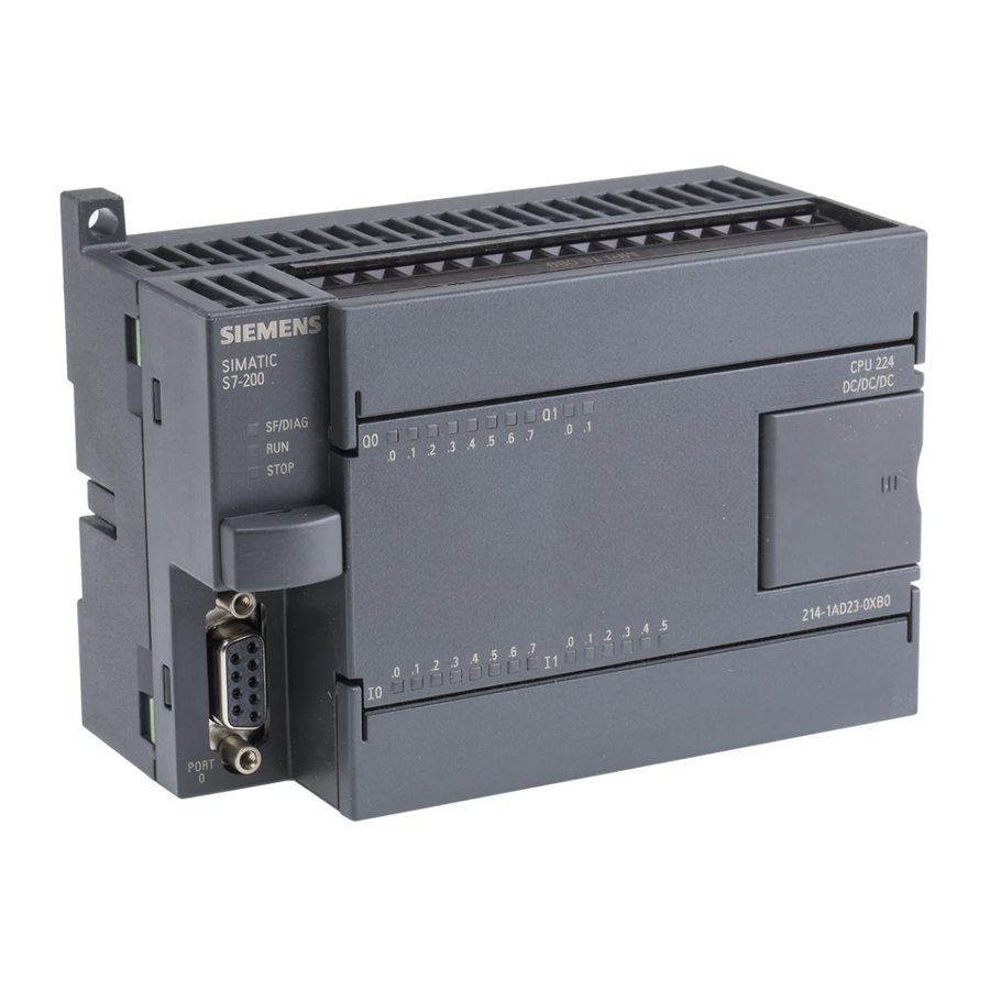
Page 8: Details Of The S7-200 (Cpu 222)
Installing the hardware 1.2 Details of the S7-200 (CPU 222) Details of the S7-200 (CPU 222) Getting Started - Beginners Training Documents, 07/2007, A5E01031470B... -
Page 9: Wiring Diagrams For The Assembled Hardware
Installing the hardware 1.3 Wiring diagrams for the assembled hardware Wiring diagrams for the assembled hardware Wiring diagram for the assembled hardware Connect the bold wires as shown in the diagram below. The gray wire is only mechanically attached to the output simulator. Either end of the gray wire can be connected to L+ or 1L. gray Getting Started - Beginners Training Documents, 07/2007, A5E01031470B... - Page 10 Installing the hardware 1.3 Wiring diagrams for the assembled hardware Circuit diagram for the assembled hardware Getting Started - Beginners Training Documents, 07/2007, A5E01031470B...
- Page 11 Installing the hardware 1.3 Wiring diagrams for the assembled hardware Wiring diagram of the S7-200 (CPU 222 AC/DC/RLY)) Getting Started - Beginners Training Documents, 07/2007, A5E01031470B...
-
Page 13: Installing The Software
Installing the software Installing STEP 7-Micro/WIN for Getting Started - Beginners In order to install the STEP 7-Micro/WIN V4 programming software you need a PC or programming device (PG) with a Microsoft Operating System. The software will run on Windows 2000 Service Pack 3 or later, Windows XP Home, or Windows XP Professional. 1. -
Page 14: Starting Step 7-Micro/Win
Installing the software 2.2 Starting STEP 7-Micro/WIN Starting STEP 7-Micro/WIN From the Windows Start menu, select the SIMATIC > STEP 7-Micro/WIN V4.0.x.xx > STEP 7-Micro/WIN to start the STEP7-Micro/WIN programming software. Getting Started - Beginners Training Documents, 07/2007, A5E01031470B... -
Page 15: Using The Help System
If your computer has access to the Internet you can download or retrieve information about SIMATIC S7-200 hardware and software using the S7-200 on the Web menu item in the Help menu. -
Page 17: Basic Settings
Basic settings Connecting the communication cable The PC/PPI Programming Cable (USB/RS 485) connects a PC to the S7-200 PLC. On your PC, use a standard Universal Serial Bus (USB) peripheral connector. Connect the USB/PPI cable to the PC and to the PLC. Supply the PLC with the operating voltage. -
Page 18: Configuring The S7-200 Communication
Basic settings 3.2 Configuring the S7-200 communication Configuring the S7-200 communication 1. Click the communications icon in the navigation bar. 2. Review the communications settings. 3. Double-click the corresponding field to refresh. The connected CPU should now be recognized and registered automatically. 4. -
Page 19: Performing The First Function Test
Basic settings 3.3 Performing the first function test Performing the first function test To perform the first function test, follow the steps below: 1. Set the mode selector of the PLC to the TERM or RUN position. The mode selector is located behind the small cover at the front side of the CPU. -
Page 21: First Programming Exercise
First programming exercise Writing your first program Getting Started - Beginners Training Documents, 07/2007, A5E01031470B... -
Page 22: Opening The First Programming Exercise
First programming exercise 4.2 Opening the first programming exercise Opening the first programming exercise Getting Started - Beginners Training Documents, 07/2007, A5E01031470B... -
Page 23: Downloading The First Exercise Program To The Cpu
First programming exercise 4.3 Downloading the first exercise program to the CPU Downloading the first exercise program to the CPU Runtime edits are available on the CPU 224, CPU 224XP and CPU 226. Runtime edits allow program edits while in RUN mode. You can download the program by following these steps: With the mode selector in TERM or RUN position, click the Download icon. -
Page 24: Function And Test Of The First Exercise Program
First programming exercise 4.4 Function and Test of the first exercise program Function and Test of the first exercise program In the first exercise program, switch S0 turns the motor on and off. Switch S1 changes the direction of the motor. Switches S0 and S1 are the first two switches on the input simulator. -
Page 25: Elements Of Ladder Logic (Lad)
First programming exercise 4.5 Elements of ladder logic (LAD) Elements of ladder logic (LAD) 0 and 1 are the only data states in digital control logic. The 0 state is designated as false and the 1 state is true. This is why we say a PLC scan is either 0 (false) or 1 (true). Getting Started - Beginners Training Documents, 07/2007, A5E01031470B... -
Page 26: Transforming A Circuit Diagram
First programming exercise 4.6 Transforming a circuit diagram Transforming a circuit diagram How do you transform a circuit diagram into a PLC program? Rotate your circuit diagram 90° to the left. Your power rail will then appear on the left, with the grounding rail on the right. In the middle you will see the switching elements of your circuit. -
Page 27: Elements Of The First Exercise Program
First programming exercise 4.7 Elements of the first exercise program Elements of the first exercise program Let’s have a closer look at the structure of the PLC program in a ladder diagram (LAD).This type of representation closely resembles a circuit diagram. Getting Started - Beginners Training Documents, 07/2007, A5E01031470B... -
Page 28: Status View (Online)
First programming exercise 4.8 Status view (online) Status view (online) Select the menu item Debug > Start Program Status to activate the status view of the ladder diagram. You can now view the status of the operands in the PLC. In the example, switch S0 is connected to input I0.0. -
Page 29: Statements
First programming exercise 4.9 Statements Statements Getting Started - Beginners Training Documents, 07/2007, A5E01031470B... -
Page 31: More Exercises
More exercises First program modification 5.1.1 AND logic operation Objective: Switch S2 and switch S0 must be closed to switch on the fan motor. As before, switch S1 is closed to reverse the direction of rotation of the fan motor. A description of the function shown above: The motor runs when S0 AND S2 are closed. -
Page 32: Inserting A Logic Gate
More exercises 5.1 First program modification 5.1.2 Inserting a logic gate If you want to connect a further normally-open contact for input I0.2 in series between normally-open contact I0.0 and coil Q0.0 (i.e. insert an AND link between I0.0 and I0.2), you first need to select a valid location to put the new contact. -
Page 33: Entering The Operand And Testing
More exercises 5.1 First program modification 5.1.3 Entering the operand and testing After you insert the new contact, you must specify the correct operand. Click the operand field and then input the operand: I0.2. Press the Enter key to confirm the input. Don’t forget to save your changes! Click the field with the mouse at any time to select it again. -
Page 34: Deleting A Contact Or An Operand
More exercises 5.1 First program modification 5.1.4 Deleting a contact or an operand If you want to delete the I0.2 contact, select the contact with the mouse and press the DEL key. You must reconnect I0.0 to Q0.0 by clicking the Line Right button. If you want to delete a selection, row, column, vertical, network(s) or POU proceed as follows:... -
Page 35: Second Modification To The Program
More exercises 5.2 Second modification to the program Second modification to the program 5.2.1 OR logic operation Objective: Switches S0 and S2 are to be actuated in order to switch on the motor. Switch S3 alone is to be used as an alternative in order to switch on the motor. -
Page 36: Inserting An Or Element
More exercises 5.2 Second modification to the program 5.2.2 Inserting an OR element Use the mouse to select a free position in the same network and insert a normally-open contact at this location. Click the mouse on the Line Up button in the LAD toolbar Now the parallel OR branch is complete. -
Page 37: Third Modification To The Program
More exercises 5.3 Third modification to the program Third modification to the program 5.3.1 On-delay timer Objective: In the following program modification, you insert an on-delay timer in exercise program 1. When input I0.3 (S3) is activated on the simulator, a waiting time is started. Output Q0.0, and thus the motor, is not activated until the waiting time has expired. -
Page 38: Understanding The On-Delay Timer Function
More exercises 5.3 Third modification to the program 5.3.2 Understanding the on-delay timer function Getting Started - Beginners Training Documents, 07/2007, A5E01031470B... -
Page 39: Programming The On-Delay Timer
More exercises 5.3 Third modification to the program 5.3.3 Programming the on-delay timer Getting Started - Beginners Training Documents, 07/2007, A5E01031470B... -
Page 40: Working With Projects
More exercises 5.4 Working with projects Working with projects 5.4.1 Programming with symbols So far you have been working in the PLC program with operands in the "PLC language" such as I0.3 or T34, but if the program is longer, it is not easy to associate these operands with their actual function within a control system. - Page 41 More exercises 5.4 Working with projects Using a symbol in a network Getting Started - Beginners Training Documents, 07/2007, A5E01031470B...
-
Page 42: Creating A New Project
More exercises 5.4 Working with projects 5.4.2 Creating a new project If you want to write a new program of your own, you need a sort of container to put your program file in. In STEP 7-Micro/WIN, this container is the project. An S7-200 project contains all additional information for your project, for example, the symbol table and comments etc. - Page 43 More exercises 5.4 Working with projects Save the project under a new name Getting Started - Beginners Training Documents, 07/2007, A5E01031470B...
- Page 44 More exercises 5.4 Working with projects Getting Started - Beginners Training Documents, 07/2007, A5E01031470B...
-
Page 45: Do You Want To Learn More
Getting Started - Advanced and the "Tips & Tricks" from your SIMATIC representative. You will find more information in the manuals for the S7-200. For further training you can attend a S7-200 course at your Siemens Training Center or with your SIMATIC representative. -
Page 47: Appendix
Appendix Of bits, bytes and words ... The smallest unit of information in a digital system is known as a "bit". A bit can only have the states "0" (false or not true) or "1" (true). A light switch, for example, only has the states "light on" or "light off". The value of the light switch in answer to the question "Is the light on?"... -
Page 48: Address Areas Of The S7-200
Appendix A.2 Address areas of the S7-200 Address areas of the S7-200 The diagram below shows the memory addresses of the S7-200 PLC where inputs and outputs are mapped. For example, if a voltage is applied to a physical input, this "1" signal is mapped at an address in the memory that is assigned to this input. -
Page 49: Cyclic Program Execution In The S7-200 Plc
Appendix A.3 Cyclic program execution in the S7-200 PLC Cyclic program execution in the S7-200 PLC All SIMATIC PLCs operate a scan cycle. During each cycle, the external switch states are first read in from the inputs, and then stored in the process-image input table. The control program is then executed on the basis of the image values.