
Related Manuals for Siemens SIMOTION D4 Series


Summary of Contents for Siemens SIMOTION D4 Series
- Page 1 Preface Introduction Description Operator control (hardware) SIMOTION D4xx Interfaces Technical Data Equipment Manual Dimension drawings Spare parts/accessories Appendices ESD guidelines 12.2004 6AU1900-1AJ32-0BA0...
- Page 2 Trademarks All names identified by ® are registered trademarks of the Siemens AG. The remaining trademarks in this publication may be trademarks whose use by third parties for their own purposes could violate the rights of the owner.
- Page 3 Preface Contents of manual This manual describes the SIMOTION D425, D435, and D445 devices. This document is part of the SIMOTION D documentation package with order number: 6AU1900-1AJ32-0BA0 12.2004 Edition Scope This manual is applicable for SIMOTION D425, SIMOTION D435, and SIMOTION D445. Standards The SIMOTION system was developed according to the quality guidelines of ISO 9001.
- Page 4 • A & D Technical Support: Phone: +49 (180) 50 50 222 • Fax: +49 (180) 50 50 223 • E-mail: ad.support@siemens.com If you have any questions, suggestions, or corrections regarding the documentation, please send them to the following fax number or e-mail address: •...
- Page 5 ASICs. SIMOTION D4xxx is recyclable due to its environmentally compatible materials. For environmentally friendly recycling and appropriate disposal of your old components, please contact your local Automation & Drives representative. Contact details can be found in our contacts database on the Internet at: http://www3.ad.siemens.de/partner/search.asp D4xx Manual, 12.2004, 6AU1900-1AJ32-0BA0...
-
Page 7: Table Of Contents
Table of contents Preface ..............................iii Introduction............................. 1-1 Hardware components....................... 1-1 Product description of D4xx ....................... 1-2 Software components ........................ 1-2 Product variants ......................... 1-3 System components ........................1-5 Description.............................. 2-1 Safety notes ..........................2-1 D435 and D425 .......................... 2-2 D445............................ - Page 8 Table of contents 4.3.1 Ethernet interfaces X120 and X130 ................... 4-4 4.3.2 Use of Ethernet interfaces......................4-5 Digital inputs/outputs........................4-6 4.4.1 X122 and X132 digital inputs ..................... 4-6 4.4.2 Pin assignment for interfaces X122 and X132................4-8 4.4.3 Technical data for X122 and X132..................... 4-9 4.4.4 Use of X122 and X123 interfaces ....................
- Page 9 Table of contents Basic measures for protection against discharge of static electricity ........B-3 Index Tables Table 1-1 Product variants ......................... 1-3 Table 1-2 Central components........................1-5 Table 1-3 System components ........................1-5 Table 1-4 Distributed I/O systems......................1-6 Table 1-5 Optional components for the control unit: ..................
- Page 10 Table of contents Table 5-6 Electrical connection values....................... 5-3 Table 5-7 Dimensions and weight of a D445 ..................... 5-3 Table 5-8 Environmental requirements ...................... 5-3 Table 7-1 Overview of TB30 interface......................7-5 Table 7-2 Interface overview of the TM31....................7-5 Table 7-3 TM41 interface overview ......................
-
Page 11: Introduction
Introduction Hardware components SIMOTION runtime module and SINAMICS drive module As the central hardware, SIMOTION D uses the SIMOTION D4xx as a control unit consisting of the SIMOTION runtime module and the SINAMICS firmware. The control unit uses the SINAMICS Integrated drive with various SINAMICS S120 drive modules (line and motor modules) to perform open-loop and closed-loop control of the axis assembly. -
Page 12: Product Description Of D4Xx
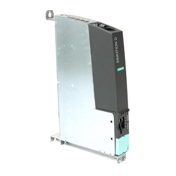
Introduction 1.2 Product description of D4xx In general, a SIMOTION D axis assembly consists of the following elements: • SIMOTION D (control unit) (1) This unit contains the programmable runtime system of SIMOTION and the drive software of SINAMICS S120. As a general principle, SIMOTION D is capable of controlling multiple axes/drives. -
Page 13: Product Variants
Introduction 1.4 Product variants SINAMICS S120 closed-loop drive control including the following functions: • Closed-loop current and torque control • Closed-loop speed control • Regulated infeed Product variants SIMOTION D There are several variants of SIMOTION D (differing in performance and number of axes that can be operated): The following table shows the different SIMOTION D versions. - Page 14 Introduction 1.4 Product variants The following figure shows a possible system configuration with a SIMOTION D435. Figure 1-2 System configuration using SIMOTION D with two axes each Note In order to cover all variants of SIMOTION D, the product will be referred to as "D4xx". Specific product designations will be used for information that applies only to one product version, e.g., D435.
-
Page 15: System Components
Introduction 1.5 System components System components Introduction The most important components of the system and their functions are shown below. Table 1-2 Central components Component Function Control unit ... The central unit in the axis assembly You can use the integrated fast digital I/O as: Homing inputs •... -
Page 16: Table 1-4 Distributed I/O Systems
Introduction 1.5 System components Component Function automation landscape by means of Ethernet interfaces: Programming devices (PGs/PCs) • SIMATIC HMI devices • Other devices via UDP • Distributed I/O systems The control unit can communicate via two PROFIBUS-DP interfaces with the following distributed I/O systems: Table 1-4 Distributed I/O systems... -
Page 17: Table 1-6 Additional Components That Can Be Connected To The Control Unit
Introduction 1.5 System components Component Function Feature are used to implement measuring inputs and cam outputs. In addition, these terminal modules provide drive-related digital inputs and outputs with short signal delay times. Sensor module cabinets (SMC) ... Enables acquisition of encoder data from connected motors via DRIVE CLiQ Operator input and monitoring components Table 1-6... - Page 18 A detailed, regularly updated list of the I/O modules approved for use with SIMOTION, as well as notes on their use, can be found on the Internet at: http://www4.ad.siemens.de/view/cs/en/11886029 Besides the I/O modules released for use with SIMOTION, in principle, any certified standard slave that supports cyclic data exchange (DP V0) and, if required, acyclic data exchange (DP V1) can be connected to SIMOTION.
-
Page 19: Description
Description Safety notes Note safety information Note the following safety information when working with the control unit and its components. Caution An option board may only be inserted and removed when the control unit and option board are disconnected from the power supply. Notice The 80 mm clearances above and below the components must be observed. -
Page 20: D435 And D425
Description 2.2 D435 and D425 D435 and D425 Device image The following figure shows a control unit with its interfaces and front panel components (fault and status displays). Figure 2-1 Position of interfaces and front panel components D4xx Manual, 12.2004, 6AU1900-1AJ32-0BA0... -
Page 21: D445
Description 2.3 D445 D445 Device image The following figure shows the control unit with its interfaces and front panel components (fault and status displays). Figure 2-2 Interfaces and display elements D4xx Manual, 12.2004, 6AU1900-1AJ32-0BA0... -
Page 22: Clock
Description 2.4 Clock Caution This control unit must be operated with a fan/battery module for heat dissipation. Without a fan/battery module, the control unit will not start up and cannot be commissioned. Clock Features of real-time clock The following table contains the features and functions of the control unit clock. Table 2-1 Clock features Features... -
Page 23: Power Supply Of D425 And D435
Description 2.5 Power supply of D425 and D435 Power supply of D425 and D435 External 24 V power supply Power is supplied to the control unit by an external 24 V power supply (e.g., SITOP). Table 2-2 Input voltage specification Input voltage Typical power Maximum power... -
Page 24: Power Supply Of D445
Description 2.6 Power supply of D445 Power supply of D445 External 24 V power supply Power is supplied to this control unit by an external 24 V power supply (e.g., SITOP). Table 2-3 Input voltage specification Input voltage Typical power Maximum power consumption consumption... -
Page 25: Operator Control (Hardware)
Operator control (hardware) Operator control and display elements 3.1.1 LED displays Arrangement of LED displays The front panel of the control unit has eight LED displays arranged in two rows of four. The following table indicates the possible LED states and their meaning. 7-segment display Figure 3-1 LED display on control unit... -
Page 26: Table 3-1 Meaning Of Led States
Operator control (hardware) 3.1 Operator control and display elements Note While the control unit is starting up, all LEDs are illuminated yellow for a brief time. You can carry out a detailed diagnosis using a PG/PC and the Engineering System. LED displays Table 3-1 Meaning of LED states... - Page 27 Operator control (hardware) 3.1 Operator control and display elements Name Function State Meaning Technology/optional objects under license are, for example: Position (position axis) • Cam (synchronous axes with • connected cam) Gear (synchronous axes with • gearing) Sublicensing is therefore indicated only when no technological events that can be acknowledged are pending.
- Page 28 Operator control (hardware) 3.1 Operator control and display elements Name Function State Meaning DP2 is defined as an i-slave: A parameter assignment master is not present. Flashing green (0.5 Hz) PROFIBUS channel is ready to communicate; cyclic communication is not taking place (bus status: Clear). Green PROFIBUS channel is ready to communicate;...
-
Page 29: Nameplates
Operator control (hardware) 3.1 Operator control and display elements 3.1.2 Nameplates Lateral nameplate The following figure shows you all the information included in the nameplate located on the side of the unit. Figure 3-2 Nameplate You might need to access the information provided on the side-mounted nameplate after the D4xx has been mounted. -
Page 30: Interfaces
Operator control (hardware) 3.1 Operator control and display elements MAC addresses A second nameplate for the MAC addresses of the two Ethernet interfaces is attached to the front panel: MAC address of X120 MAC address of X130 Figure 3-3 MAC addresses You can see this nameplate when you open the front cover of the control unit. -
Page 31: Mode Selector
Operator control (hardware) 3.1 Operator control and display elements 3.1.3 Mode selector Mode selector positions Note It is recommended that SIMOTION SCOUT be used exclusively to switch the operating modes of the module. Do to so, leave the mode selector at position 0 (RUN). The mode selector cannot be changed mechanically when a BOP is installed. -
Page 32: Reset Button
Operator control (hardware) 3.1 Operator control and display elements Table 3-3 Mode selector settings Meaning Explanations The control unit is processing the user program and the associated system outputs: Reading process image of inputs • Processing user programs assigned to the execution system •... -
Page 33: Simotion Cf
Operator control (hardware) 3.2 SIMOTION CF SIMOTION CF 3.2.1 Properties of the CompactFlash card CompactFlash card The CompactFlash card is mandatory for operation of the control unit. The SIMOTION kernel and the software used to control the drives (SINAMICS firmware) are contained on the CompactFlash card. -
Page 34: Compactflash Slot
Operator control (hardware) 3.2 SIMOTION CF 3.2.2 CompactFlash slot Location of the CompactFlash slot The CompactFlash does not extend beyond the housing. An ergonomic recessed grip enables the card to be removed. Figure 3-5 View of control unit with closed protective cover D4xx 3-10 Manual, 12.2004, 6AU1900-1AJ32-0BA0... -
Page 35: Changing The Compact Flash Card
Operator control (hardware) 3.2 SIMOTION CF 3.2.3 Changing the Compact Flash card Procedure Proceed as follows: 1. Switch off the power supply. 2. Remove the CompactFlash card from the control unit. 3. Take hold of the thumb grip between your thumb and forefinger and withdraw the card. 4. -
Page 36: Writing To Compactflash Card
Operator control (hardware) 3.2 SIMOTION CF 3.2.4 Writing to CompactFlash card Writing to the the CompactFlash card You can write to the CompactFlash card as follows: • The CompactFlash card is inserted in the control unit and is written to using the Copy RAM to ROM menu command (the programming device must be connected to module). -
Page 37: Memory Concept
Operator control (hardware) 3.3 Memory concept Memory concept 3.3.1 Memory concept of SIMOTION D Memory concept The following figure and the description of items 1 to 3 below provide an overview of the memory model for the D4xx and sequences for certain operator actions. Figure 3-7 Memory model for D4xx D4xx... -
Page 38: Persistent Data (Non-Volatile Data)
Operator control (hardware) 3.3 Memory concept 3.3.2 Persistent data (non-volatile data) SRAM backup In the D4xx, the integrated SRAM, which is buffered internally, is used for persistent data storage. For information on the usable area for retain data, refer to the SIMOTION SCOUT Configuration Manual. - Page 39 Operator control (hardware) 3.3 Memory concept Diagnostics buffer entries The following errors are entered once in the diagnostics buffer when they occur: Table 3-4 Alarm messages of the diagnostics buffer Alarm entry Meaning Remedy Level 1 battery voltage warning Battery voltage below Replace battery in the prewarning level fan/battery module.
-
Page 40: Power Off Behavior
Operator control (hardware) 3.3 Memory concept 3.3.4 Power off behavior Power failure During a power failure, the data in the SRAM of the control unit are backed up by an internal SuperCap and the optional fan/battery module. The nonvolatile data are available for the next startup. Thus, the control unit is immediately operational without data loss. -
Page 41: Interfaces
Interfaces Interface overview Available interfaces Table 4-1 Overview of available external interfaces Interface Name Connector type DRIVE CLiQ interface (0) X100 DRIVE CLiQ plug DRIVE CLiQ interface (1) X101 DRIVE CLiQ plug DRIVE CLiQ interface (2) X102 DRIVE CLiQ plug DRIVE CLiQ interface (3) X103 DRIVE CLiQ plug... -
Page 42: Drive Cliq Interfaces
Interfaces 4.2 DRIVE CLiQ interfaces Non-usable interfaces Table 4-2 Overview of interfaces that cannot be used for SIMOTION D Interface name Interface Connector type 1. USB interface X125 USB socket 2. USB interface X135 USB socket RS232 interface X140 9-pin Sub-D pins DRIVE CLiQ interfaces 4.2.1 DRIVE CLiQ interfaces... -
Page 43: Use Of Drive Cliq Interface
Interfaces 4.2 DRIVE CLiQ interfaces Signal name Signal type Meaning Reserved, do not use Receive data - Reserved, do not use Reserved, do not use + (24 V) Voltage supply for DRIVE CLiQ, 450 mA maximum M (0 V) Ground to 24 V Signal type: I = Input;... -
Page 44: Ethernet Interfaces
Interfaces 4.3 Ethernet interfaces Ethernet interfaces 4.3.1 Ethernet interfaces X120 and X130 Features The X120 and X130 interfaces are full-duplex 10/100-Mbit Ethernet ports. Both ports are connected as an Ethernet terminal device. Interface features Table 4-5 X120 and X130 Features Type Connector type RJ45 socket connector... -
Page 45: Use Of Ethernet Interfaces
Interfaces 4.3 Ethernet interfaces Position of connectors The following figure shows the mounting position and designation of the Ethernet connectors on the module. Figure 4-2 Ethernet interface 4.3.2 Use of Ethernet interfaces Application Interfaces for connection to Industrial Ethernet. Industrial Ethernet is a communication network with a transmission rate of 10/100 Mbit/s. The D4xx offers the following functions via Ethernet interfaces: •... -
Page 46: Digital Inputs/Outputs
Interfaces 4.4 Digital inputs/outputs Digital inputs/outputs 4.4.1 X122 and X132 digital inputs Interface features Table 4-7 Interfaces X122 and X132 Features Type Connector type Micro Combicon Connection possibility: up to 0,5 mm Current carrying capacity 4 A, maximum Position of connectors X122 X132 Figure 4-3... - Page 47 Interfaces 4.4 Digital inputs/outputs Wiring and block diagram for SIMOTION D using SIMOTION D435 as an example The following figure shows the wiring diagram and the block diagram of the digital inputs and digital inputs/outputs of the SIMOTION D435. Figure 4-4 Wiring diagram and block diagram of the digital inputs/outputs D4xx Manual, 12.2004, 6AU1900-1AJ32-0BA0...
-
Page 48: Pin Assignment For Interfaces X122 And X132
Interfaces 4.4 Digital inputs/outputs 4.4.2 Pin assignment for interfaces X122 and X132 Interface assignment of X122 and X132 Table 4-8 X122 Digital inputs/outputs Signal name Signal type Meaning Digital input 0 Digital input 0 Digital input 0 Digital input 0 Ground for DI0 - DI3 (functionally-separated relative to M) -
Page 49: Technical Data For X122 And X132
Interfaces 4.4 Digital inputs/outputs X132 Digital inputs/outputs Signal name Signal type Meaning Digital input 4 Digital input 5 Digital input 6 Digital input 7 Ground for DI4 – DI7 (functionally-separated relative to M) Ground DI/DO12 Digital input/output 12 DI/DO13 Digital input/output 13 (fast input) Ground DI/DO14... -
Page 50: Use Of X122 And X123 Interfaces
Interfaces 4.4 Digital inputs/outputs Digital inputs/outputs on X122/X132 Table 4-10 Technical data of the digital inputs/output of X122/X132 parameters Values As an input Voltage -3 V to 30 V Typical power consumption 10 mA at 24 VDC Signal level (including ripple factor) High signal level: 15 V to 30 V Low signal level: -3 V to 5 V Pins 8, 10, and 11 are "fast inputs"... -
Page 51: Power Supply
Interfaces 4.5 Power supply The enables for the drive units and/or motors (active line module, motor module) connected to the control unit can be switched using the digital inputs. Electrically isolated inputs The control unit has 8 digital inputs. The isolated inputs can be used as freely addressable inputs. Bidirectional inputs/outputs The control unit has 8 digital inputs/outputs. -
Page 52: Profibus-Dp Interfaces
Interfaces 4.6 PROFIBUS-DP interfaces Note The 24 V is looped through via the 24 V connector. In this case, pin 1 is jumpered with pin 2, and pin 3 is jumpered with pin 4. Position of power supply interface Figure 4-5 Power supply interface Application of X124 This interface is provided exclusively for connection to the external power supply. -
Page 53: Table 4-14 Profibus-Dp X126 Interface
Interfaces 4.6 PROFIBUS-DP interfaces Interface assignment for X126 Table 4-14 PROFIBUS-DP X126 interface Signal name Signal type Meaning Ground to P24_SERV 1RS_DP RS-485 differential signal 1RTS_DP Request to send Ground to 1P5 5 V power supply for bus terminal, external, short-circuit proof P24_SERV 24 V for teleservice,... -
Page 54: Use Of Profibus-Dp Interfaces
Interfaces 4.6 PROFIBUS-DP interfaces Position of connectors The following figure shows the mounting position and designation of the connectors on the control unit. DP2/MPI X136 X126 Figure 4-6 Position of connectors X126, X136 4.6.2 Use of PROFIBUS-DP interfaces Connectable devices The following devices can be connected to the PROFIBUS DP interfaces: •... -
Page 55: Compactflash Slot
Interfaces 4.7 CompactFlash slot CompactFlash slot 4.7.1 Compact Flash slot Features Type: 50-pin socket connector This interface should only be used to insert a special SIMOTION CF. Consult the relevant references for detailed information about SIMOTION CF. Measuring sockets 4.8.1 Measuring sockets X131 - X134 Application The measuring sockets are used to output analog signals. - Page 56 Interfaces 4.8 Measuring sockets Measuring socket position Figure 4-7 Measuring socket arrangement D4xx 4-16 Manual, 12.2004, 6AU1900-1AJ32-0BA0...
-
Page 57: Technical Data
Technical Data Technical data for D435 and D425 Technical Data The following technical data are relevant for the D435 and D425. Additional references For information on system clocks and address ranges of the SIMOTION D435 and SIMOTION D425, refer to the SIMOTION SCOUT configuration manual. Memory for user data Table 5-1 Memories for user data and their memory size... -
Page 58: Technical Data For D445
Technical Data 5.2 Technical data for D445 parameters Values Without mounting and fan/battery module With 50x380x230 mounting and fan/battery module (max. expansion) 50x380x270 Weight of SIMOTION D [g] Approximately 2500 Weight of SIMOTION CF [g] Ambient conditions Table 5-4 Environmental requirements parameters Values Permissible ambient temperature... - Page 59 Technical Data 5.2 Technical data for D445 Connection values Table 5-6 Electrical connection values parameters Value range Supply voltage VDC (permissible range: 20,4 ... 28.8 V) Power consumption from 24 V Typical power consumption: 2 A (with no load at inputs/outputs, no supply from DRIVE CLiQ I/O or PROFIBUS) Power loss 15 W...
-
Page 61: Dimension Drawings
Dimension drawings Dimension drawing of D435 and D425 Dimension drawings Figure 6-1 Dimensions of D435 and D425 D4xx Manual, 12.2004, 6AU1900-1AJ32-0BA0... -
Page 62: Dimension Drawing Of D445
Dimension drawings 6.2 Dimension drawing of D445 Dimension drawing of D445 Dimension drawings Figure 6-2 Dimensions of a D445 D4xx Manual, 12.2004, 6AU1900-1AJ32-0BA0... -
Page 63: Spare Parts/Accessories
Spare parts/accessories Fan/battery module 7.1.1 Cooling the SIMOTION D4xx Using a fan/battery module If there is insufficient free convection for heat dissipation of the control unit (with an ambient temperature greater than 55° C), an external fan/battery module can be mounted on the underside of the control unit. -
Page 64: Fan/Battery Module Assembly
Spare parts/accessories 7.1 Fan/battery module Battery A 3 V lithium battery can be inserted in the fan/battery module. The battery is preassembled with an approximately 4 cm long cable with plug. The appropriate mating connector is attached to a small printed circuit board for connection in the fan/battery module. 7.1.2 Fan/battery module assembly Procedure... -
Page 65: Battery Replacement In The Fan/Battery Module
Spare parts/accessories 7.1 Fan/battery module 7.1.3 Battery replacement in the fan/battery module. Procedure Proceed as follows to replace the battery: 1. Gently press the fan/battery module backwards. This detaches the module from its front latching device. 2. Tilt the fan/battery module forwards at an angle and pull out the plastic guide from the recess of the control unit. -
Page 66: Supplemental System Components
Spare parts/accessories 7.2 Supplemental system components Supplemental system components Connection options for supplemental system components Figure 7-3 Position of supplemental system components D4xx Manual, 12.2004, 6AU1900-1AJ32-0BA0... -
Page 67: Terminal Board Tb30
Spare parts/accessories 7.3 Terminal board TB30 Terminal board TB30 Features of the TB30 The TB30 is a terminal expansion module that can be inserted in the D4xx. The TB30 contains the following terminals: Table 7-1 Overview of TB30 interface Interface Number Digital inputs Digital outputs... -
Page 68: Terminal Module Tm41
Spare parts/accessories 7.5 Terminal module TM41 Interface Number Analog inputs Analog outputs Temperature sensor input (KTY84-130 or PTC) Additional references You can find additional information about the TM31 in the SINAMICS S120 product manual and the SINAMICS S120 commissioning manual. Caution The 50 mm clearances above and below the components must be observed. -
Page 69: Terminal Modules Tm15 And Tm17 High Feature
Spare parts/accessories 7.6 Terminal modules TM15 and TM17 High Feature Terminal modules TM15 and TM17 High Feature Features of TM15 and TM17 High Feature The terminal modules TM15 and TM17 High Feature are used to implement measuring inputs and cam outputs for SIMOTION D. In addition, these terminal modules provide drive- related digital inputs and outputs with short signal delay times. -
Page 70: Cx32 Module
Spare parts/accessories 7.7 CX32 module CX32 module Features of the CX32 (Control Extension) The CX32 module enables you to expand the performance of a SIMOTION D axis assembly. The number of connectable axes is increased. The CX32 has the following interfaces: •... -
Page 71: Appendices
Appendices Standards IEC 1131 The SIMOTION programmable controller meets the requirements and criteria of the Standard IEC 1131, Section 2. CE Designation Our products meet the general and safety-related requirements of the following EC guidelines and conform to the uniform standards (EN) for programmable controllers published in the official gazettes of the European Union: 89/336/EEC "Electromagnetic Compatibility"... -
Page 72: Rated Voltage For Operation Of The D4Xx
Appendices A.3 Rated voltage for operation of the D4xx Table A-2 Test voltages Circuits with rated voltage Ue relative to other Test voltage circuits or ground 0 V < Ue ≤ 50 V 500 V DC Safety class Safety class I in accordance with IEC 536 (VDE 0106, Part 1), i.e. a protective-conductor terminal is required on the mounting rail! Protection against ingress of solid foreign bodies and water IP 20 degree of protection in accordance with IEC 529, i. -
Page 73: Safety Of Electronic Controllers
Appendices A.4 Safety of electronic controllers Safety of electronic controllers Introduction The remarks made here relate to fundamental criteria and apply irrespective of the type of controller and the manufacturer. Reliability The reliability of devices and components is maintained at the highest possible level thanks to comprehensive and cost-effective measures implemented during the development and manufacturing processes. -
Page 74: Ec Declaration Of Conformity
EC Declaration of Conformity Calling the Declaration of Conformity SIMOTION D4xx product manual Order no.: 6AU1900-0BK32-0AA0 To access the current Declaration of Conformity on the Internet, go to: http://www4.ad.siemens.de/view/cs/en/15257461 D4xx Manual, 12.2004, 6AU1900-1AJ32-0BA0... -
Page 75: Esd Guidelines
ESD guidelines Electrostatically sensitive modules Definition All electronic modules are equipped with highly integrated modules or components. Because of the technology used, these electronic components are very sensitive to overvoltages and thus to discharge of static electricity. The acronym ESD has become the established designation for such Electrostatically Sensitive Devices. -
Page 76: Electrostatic Accumulation On Individuals
ESD guidelines B.2 Electrostatic accumulation on individuals Electrostatic accumulation on individuals Accumulating an electrostatic charge Anyone who is not conductively connected to the electrical potential of their environment can accumulate an electrostatic charge. The figure below shows the maximum electrostatic voltages that can accumulate on a person who is operating equipment when he/she comes into contact with the materials indicated. -
Page 77: Basic Measures For Protection Against Discharge Of Static Electricity
ESD guidelines B.3 Basic measures for protection against discharge of static electricity Basic measures for protection against discharge of static electricity Ensure proper grounding When working with electrostatically sensitive devices, make sure that the you, your workstation, and the packaging are properly grounded. This prevents the accumulation of static electricity. -
Page 79: Index
Index Axis assembly, 1-1 Fan/battery module Battery replacement, 7-3 Features, 7-1 Installation, 7-2 Compact Flash slot, 4-15 CompactFlash card Changing, 3-11 CompactFlash card Interface Slot, 3-10 Compact Flash slot, 4-15 CompactFlash card Digital I/O, 4-6 Features, 3-9 DRIVE CLiQ, 4-2 Formatting, 3-12 Ethernet, 4-4 Writing to, 3-12... - Page 80 Index Power supply, 2-5, 2-6 Power supply interface Assignment, 4-11 PROFIBUS interface Assignment, 4-13 Real-time clock, 2-4 Reset Button, 3-8 Performing, 3-8 SIMOTION D D445, 1-3 Memory concept, 3-13 Product variants, 1-3 SRAM, 3-14 SRAM, 3-14 System components, 1-5 Technical Data D425, 5-1 D435, 5-1 D445, 5-2...