Table of Contents
Advertisement
Quick Links
SIMOTION D4x5-2
SIMOTION
SIMOTION D4x5-2
Manual
Valid for SIMOTION D445-2 DP/PN and D455-2
DP/PN as well as CX32-2 and TB30
11/2010
___________________
Preface
___________________
Description
___________________
Operation (hardware)
___________________
Interfaces
___________________
Technical data of the D4x5-2
___________________
Dimension drawings
Supplementary system
___________________
components
___________________
Available spare parts and
accessories
___________________
Standards and approvals
___________________
ESD guidelines
1
2
3
4
5
6
7
A
B
Advertisement
Table of Contents

Related Manuals for Siemens SIMOTION D4 Series


Summary of Contents for Siemens SIMOTION D4 Series
- Page 1 ___________________ SIMOTION D4x5-2 Preface ___________________ Description ___________________ Operation (hardware) SIMOTION ___________________ Interfaces ___________________ SIMOTION D4x5-2 Technical data of the D4x5-2 ___________________ Dimension drawings Manual Supplementary system ___________________ components ___________________ Available spare parts and accessories ___________________ Standards and approvals ___________________ ESD guidelines Valid for SIMOTION D445-2 DP/PN and D455-2 DP/PN as well as CX32-2 and TB30 11/2010...
- Page 2 Note the following: WARNING Siemens products may only be used for the applications described in the catalog and in the relevant technical documentation. If products and components from other manufacturers are used, these must be recommended or approved by Siemens. Proper transport, storage, installation, assembly, commissioning, operation and maintenance are required to ensure that the products operate safely and without any problems.
-
Page 3: Preface
Preface Content of the Manual This document is part of the SIMOTION D documentation package. Scope SIMOTION D4x5-2 Manual is applicable to the SIMOTION D445-2 DP/PN and SIMOTION D455-2 DP/PN devices as well as the CX32-2 and TB30 supplementary system components. - Page 4 My Documentation Manager Click the following link for information on how to compile documentation individually on the basis of Siemens content and how to adapt this for the purpose of your own machine documentation: http://www.siemens.com/mdm SIMOTION D4x5-2...
- Page 5 Preface Training Click the following link for information on SITRAIN - Siemens training courses for automation products, systems and solutions: http://www.siemens.com/sitrain FAQs You can find Frequently Asked Questions on the Service&Support pages under Product Support: http://support.automation.siemens.com Technical support Country-specific telephone numbers for technical support are provided on the Internet under Contact: http://www.siemens.com/automation/service&support...
- Page 6 Preface Further information / FAQs You can find further information on this manual under the following FAQs: http://support.automation.siemens.com/WW/view/de/27585482 You can also find additional information such as: ● SIMOTION Utilities & Applications: SIMOTION Utilities & Applications will be included in the SIMOTION SCOUT scope of delivery and, along with FAQs, also contain free utilities (e.g.
-
Page 7: Table Of Contents
Table of contents Preface ..............................3 Description............................... 11 System overview ..........................11 System components ........................16 I/O integration..........................20 View of SIMOTION D445-2 DP/PN and D455-2 DP/PN .............22 Nameplates ..........................23 Safety notes ..........................25 CompactFlash card........................26 1.7.1 Usage and function of the CompactFlash Card................26 1.7.2 CompactFlash card........................28 1.7.3... - Page 8 Table of contents Mechanical and climatic ambient conditions................64 Dimensions and weights ......................66 Power supply..........................67 Interfaces and performance features ..................68 CompactFlash card ........................72 Clock ............................72 Input and output circuit........................ 73 Dimension drawings ..........................75 Dimension drawing of D445-2 DP/PN and D455-2 DP/PN............75 CAD data, dimension drawings, and circuit-diagram macros .............
- Page 9 Table of contents Terminal Module TM54F......................107 Terminal modules TM15 and TM17 High Feature ..............109 CUA31/CUA32 control unit adapter...................110 6.10 DMC20 DRIVE-CLiQ hub ......................110 Available spare parts and accessories....................113 Available spare parts and accessories ..................113 Standards and approvals........................115 General rules..........................115 Safety of electronic controllers....................117 ESD guidelines ............................
- Page 10 Table of contents SIMOTION D4x5-2 Manual, 11/2010...
-
Page 11: Description
Description System overview Overview SIMOTION D is a drive-based version of SIMOTION based on the SINAMICS S120 drive family. With SIMOTION D, the SIMOTION PLC and motion control functionalities as well as the SINAMICS S120 drive software run on shared control hardware. SIMOTION D is available in two versions: ●... - Page 12 Description 1.1 System overview Application The SIMOTION D4x5-2 is ideally suited to applications with many coordinated axes with high clock-pulse rates. Typical applications include: ● Compact multiple-axis machines ● High-performance applications with short machine cycles ● Compact machines – Including the complete machine control in the drive –...
- Page 13 Description 1.1 System overview The integrated drive computing performance of the control units enables the operation of the following axis configurations: ● Up to six servo, six vector or twelve axes on each D4x5-2 control unit. (Drive control based on CU320-2, firmware version ≥ V4.x) ●...
- Page 14 Description 1.1 System overview Hardware components As the central hardware, SIMOTION D uses the SIMOTION D4x5-2 as control unit consisting of the SIMOTION runtime system and the SINAMICS drive control. The control unit uses the SINAMICS Integrated drive with various SINAMICS S120 drive modules (line and motor modules) to perform open-loop and closed-loop control of the axis grouping.
- Page 15 Description 1.1 System overview ● SINAMICS power units (motor modules) (3) These modules are used to control motors. It is also possible to operate SINAMICS PM340 power modules with the SINAMICS control unit adapter (CUA). A separate infeed is then unnecessary. ●...
-
Page 16: System Components
Description 1.2 System components System components Central components SIMOTION D4x5-2 communicates with automation components via the following interfaces: ● PROFIBUS DP ● Ethernet ● PROFINET IO ● DRIVE-CLiQ (DRIVE Component Link with IQ) SIMOTION D features a SINAMICS Integrated drive element. The communication with the SINAMICS Integrated is performed via PROFIBUS mechanisms (DP Integrated), i.e. - Page 17 Description 1.2 System components PROFIBUS DP The control unit can communicate with the following components via the PROFIBUS DP interfaces: Table 1- 3 Components on PROFIBUS DP Component Function Programming device (PG/PC) ... configures, parameterizes, programs, and tests with the "SIMOTION SCOUT"...
- Page 18 Description 1.2 System components Ethernet The control unit can communicate with the following components via the Ethernet interfaces or be embedded in an automation environment: Table 1- 4 Components on the Ethernet Component Function Programming device (PG/PC) ... configures, parameterizes, programs, and tests with the "SIMOTION SCOUT"...
- Page 19 Description 1.2 System components DRIVE-CLiQ The DRIVE-CLiQ interfaces permit a fast connection to the SINAMICS drive components. DRIVE-CLiQ offers the following advantages within the DRIVE-CLiQ topology rules: ● Expandability of components ● Automatic detection of components by the control unit ●...
-
Page 20: I/O Integration
Description 1.3 I/O integration Note You can find detailed information about components in the SINAMICS S110/S120 family of products in the SINAMICS S110/S120 manuals. It is possible that older DRIVE-CLiQ components can no longer be used with SIMOTION D4x5-2/CX32-2. Detailed information can be found at "Migration of D4x5 to D4x5-2" in Section Permissible combinations. - Page 21 "driver blocks" , e.g. in the form of function blocks, that permit (or simplify) integration. For modules released with SIMOTION (e.g. SIMATIC S7-300 module FM 350-1, etc.), these driver blocks are part of the SIMOTION SCOUT engineering system command library. See also On the Internet at: (http://support.automation.siemens.com/WW/view/en/11886029) SIMOTION D4x5-2 Manual, 11/2010...
-
Page 22: View Of Simotion D445-2 Dp/Pn And D455-2 Dp/Pn
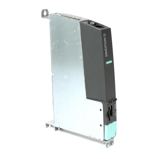
Description 1.4 View of SIMOTION D445-2 DP/PN and D455-2 DP/PN View of SIMOTION D445-2 DP/PN and D455-2 DP/PN The following figure shows the SIMOTION D445-2 and D455-2 with its interfaces and front panel elements (fault and status displays). Figure 1-2 View of D445-2 DP/PN and D455-2 DP/PN SIMOTION D4x5-2 Manual, 11/2010... -
Page 23: Nameplates
Description 1.5 Nameplates CAUTION SIMOTION D445-2 DP/PN and D455-2 DP/PN must be operated with a double fan/battery module for heat dissipation. Without this module, the control units will not start up and cannot be commissioned. Information on how to install the double fan/battery module can be found in "Supplementary system components", in Section Installing the fan/battery module (Page 80). - Page 24 Description 1.5 Nameplates Note You might need to access the information provided on the side-mounted type plate after the installation. The type plate is located on the right-hand side of the module housing and is covered by a SINAMICS S120 module when mounted. For this reason, we recommend that you make a note of the serial number of the control unit prior to assembly.
-
Page 25: Safety Notes
Description 1.6 Safety notes Safety notes Note the following safety information when working with the control unit and its components. NOTICE The 80 mm clearances above and below the components must be observed. The unit protects itself from overheating by shutting down. CAUTION An option board may only be inserted and removed when the control unit and option board are disconnected from the power supply. -
Page 26: Compactflash Card
Description 1.7 CompactFlash card CompactFlash card 1.7.1 Usage and function of the CompactFlash Card The CompactFlash card (CF card) is inserted in the CF plug-in slot (X109 interface). Figure 1-5 Slot for CompactFlash card SIMOTION D4x5-2 Manual, 11/2010... - Page 27 Description 1.7 CompactFlash card The CF card does not extend beyond the housing. An ergonomic recessed grip enables the CF card to be removed. Properties of the CF card The CF card is essential for operation of the SIMOTION D4x5-2. The CF card is not supplied with the SIMOTION D4x5-2 and must be ordered separately.
-
Page 28: Compactflash Card
Description 1.7 CompactFlash card 1.7.2 CompactFlash card Type plate information The following figure shows you all the information contained on the type plate of the CF card. Figure 1-6 Type plate of the CF card Pre-installed runtime licenses The preinstalled licenses are printed on the label as Z option below the order number. Example Example with MultiAxes package Z option for D445/D445-1/D445-2/D455-2 + two TControl licenses:... -
Page 29: Data Matrix Code On Cf Card
Description 1.7 CompactFlash card Available Z options / licenses for CF cards ● Axis licenses – Pxx POS license and number (e.g. P02 = 2x POS licenses) – Gxx GEAR license and number (e.g. G03 = 3 x GEAR licenses) –... - Page 30 Description 1.7 CompactFlash card Analysis Example of a data string from the reader unit: 1P6AU1400-2PA21-0AA0-Z+ST-WOQB02934+30SST0B8365550000079001 Table 1- 8 Machine-readable identification via 2D code Characteristic Property Order number 6AU1 400-2PA21-0AA0-Z ("1P" identifier to identify the products) Serial number T-WOQB02934 ("S" identifier, item number) HW serial number ST0B8365550000079001 ("30S"...
-
Page 31: Operation (Hardware)
Operation (hardware) Overview of operator control and display elements The following figure shows the arrangement of the operator control and display elements of a SIMOTION D4x5-2. Figure 2-1 Position of operator control and display elements The lower part of the operator control and display elements has a blanking cover during operation. -
Page 32: Operator Controls
Operation (hardware) 2.2 Operator controls Figure 2-2 Operator control and display elements of D445-2 DP/PN and D455-2 DP/PN Operator controls 2.2.1 Service and operating mode switch Properties of the Service switch and mode selector SIMOTION D4x5-2 has two selector switches on the lower front side for selection of the service functions and operating modes. - Page 33 Operation (hardware) 2.2 Operator controls Figure 2-3 Selector switches for service and operating modes of the SIMOTION D4x5-2 CAUTION Always use an insulated screwdriver to turn the rotary switch. Otherwise, static electricity can destroy the switch. Mode selector The following table contains the possible mode selector positions and the associated LED displays.
- Page 34 Operation (hardware) 2.2 Operator controls The following table contains the states of the SIMOTION D4x5-2 that can be set via the mode selector. Table 2- 2 Mode selector settings Meaning Explanations SIMOTION D4x5-2 processes the user program and the associated system services: Reading process image of inputs.
- Page 35 Operation (hardware) 2.2 Operator controls Service selector switch The following table shows the possible positions of the Service selector switch. The Service selector switch positions are explained in the order in which they are arranged on the SIMOTION D4x5-2. Table 2- 3 Switch positions of the Service selector switch Service mode Selector position Meaning...
-
Page 36: Diag Button
Operation (hardware) 2.2 Operator controls 2.2.2 DIAG button Arrangement The DIAG button is located behind the blanking cover on the SIMOTION D4x5-2. Function The diagnostics data and non-volatile data is backed up on the CF card via the DIAG button. The DIAG button function therefore corresponds to the function of switch position "D"... -
Page 37: 7-Segment And Led Displays
Operation (hardware) 2.3 7-segment and LED displays 7-segment and LED displays Arrangement of the displays The front side of the SIMOTION D4x5-2 has ten LED displays arranged arranged vertically in one row. There is also a 7-segment display below the blanking cover. Figure 2-4 7-segment and LED displays on the D4x5-2 Meaning of the LED displays... - Page 38 Operation (hardware) 2.3 7-segment and LED displays Note While the SIMOTION D4x5-2 is ramping up, all LEDs are briefly illuminated in yellow. 7-segment display The 7-segment display provides further status information in addition to the LED displays. The status "6" and a flashing "." indicate that the D4x5-2 has ramped up and communication has been established to the SINAMICS Integrated.
-
Page 39: Interfaces
Interfaces Interface overview This section describes the interfaces of the SIMOTION D4x5-2. Available interfaces Table 3- 1 Overview of available interfaces Interface Name Connector type DRIVE-CLiQ interface X100 DRIVE-CLiQ socket DRIVE-CLiQ interface X101 DRIVE-CLiQ socket DRIVE-CLiQ interface X102 DRIVE-CLiQ socket DRIVE-CLiQ interface X103 DRIVE-CLiQ socket... -
Page 40: Drive-Cliq Interfaces
Interfaces 3.2 DRIVE-CLiQ interfaces Note The 3rd port of the PROFINET IO interface X150 P3 has an additional inscription. It is called X120 PN/IE-OP. This designation is not relevant for SIMOTION D. Non-usable interfaces Table 3- 2 Overview of interfaces that cannot be used for SIMOTION D Interface name Interface Connector type... - Page 41 Interfaces 3.2 DRIVE-CLiQ interfaces Position of connectors Figure 3-1 Position of the DRIVE-CLiQ interfaces on the D4x5-2 Characteristics Table 3- 3 X100 – X105 Characteristic Type Connector type DRIVE-CLiQ connector (RJ45 socket) Cable type DRIVE-CLiQ standard (inside the control cabinet) Cable type MOTION CONNECT (outside the control cabinet) Max.
-
Page 42: Ethernet Interfaces
Interfaces 3.3 Ethernet interfaces DRIVE-CLiQ pin assignment Table 3- 4 DRIVE-CLiQ interface X100 – X105 Signal name Signal type Meaning Transmit data + Transmit data - Receive data + ---- ---- Reserved, do not use ---- ---- Reserved, do not use Receive data - ---- ----... - Page 43 Interfaces 3.3 Ethernet interfaces ● Communication with other devices over TCP/IP or UDP communication ● IT communication (via SIMOTION IT DIAG, SIMOTION IT OPC XML-DA, SIMOTION IT Virtual Machine) Catalog PM 21 For more information regarding the software packages, see , refer to the list of references (separate document) for the order number.
- Page 44 Interfaces 3.3 Ethernet interfaces Note The two interfaces support Industrial Ethernet (IE). The designation of the interfaces PN/IE-NET or PN/IE has already been designed for the support of PROFINET basic services (e.g. DCP, LLDP, SNMP) via these interfaces in a future version. These PROFINET basic services provide uniform functions for the address assignment and diagnostics, but do not provide PROFINET IO communication for the connection of drives or I/O modules, for example.
-
Page 45: Profinet Io Interface
Interfaces 3.4 PROFINET IO interface Ethernet Bidirectional receive pair B+ differential signal - - - - - - Reserved, do Bidirectional not use pair C+ - - - - - - Reserved, do Bidirectional not use pair C- Ethernet Bidirectional receive pair B- differential... - Page 46 Interfaces 3.4 PROFINET IO interface Interface position The following figure contains information on the PROFINET interface of the control unit. Position of the interface, labeling of the ports and the associated displays are described. Figure 3-3 Position of the PROFINET interface X150 P1 to P3 their displays Note The 3rd port of the PROFINET IO interface X150 P3 is also designated as X120 PN/IE OP.
- Page 47 Interfaces 3.4 PROFINET IO interface Interface characteristics Table 3- 7 Ports X150 P1 to P3 Characteristic Type Connector type RJ45plus socket Cable type PROFINET Maximum cable length 100 m Minimum transmission 0.25 ms cycle Autocrossing i.e. both crossed and uncrossed cables can be used Dust protection blanking Five blanking plugs contained in the D4x5-2 scope of delivery plugs for sealing unused...
- Page 48 (separate document) for the order number. Note A list of the modules released with SIMOTION is available at (http://support.automation.siemens.com/WW/view/en/11886029). The list is updated regularly and contains information on the use of these modules. Take note of the documentation on the individual modules or devices!
-
Page 49: Digital Inputs/Outputs
Interfaces 3.5 Digital inputs/outputs Digital inputs/outputs 3.5.1 Features Interface characteristics The digital inputs and outputs on the X122, X132 and X142 connectors are for the connection of sensors and actuators. Table 3- 9 Wiring of X122, X132 and X142 Characteristics Type Connector type Mini Combicon... - Page 50 Interfaces 3.5 Digital inputs/outputs Connection and circuit diagram for SIMOTION D4x5-2 The following figure shows the connection and circuit diagram of the digital inputs and outputs on the D4x5-2. Figure 3-5 Connection and circuit diagram of the digital inputs/outputs SIMOTION D4x5-2 Manual, 11/2010...
- Page 51 Interfaces 3.5 Digital inputs/outputs Interface assignment of X122, X132 and X142 Table 3- 10 Digital inputs/outputs X122 Designation Signal type Notes DI 0 Digital input 0 DI 1 Digital input 1 DI 2 Digital input 2 DI 3 Digital input 3 DI 16 Digital input 16 DI 17...
- Page 52 Interfaces 3.5 Digital inputs/outputs Designation Signal type Notes Ground DI/DO 14 Digital input/output 14 (can also be used as input for measuring input or as input for the external zero mark) DI/DO 15 Digital input/output 15 (can also be used as input for measuring input or as input for the external zero mark) Ground DI: Digital input;...
-
Page 53: Using The Digital Inputs/Outputs
Interfaces 3.5 Digital inputs/outputs Designation Signal type Notes IN/OUT 7 Digital input/output 7 (can be used as input of a measuring input or output of an output cam) Ground IN/OUT: Bidirectional digital input/output; M: Electronic ground B = Bidirectional; GND = Reference potential (ground) 3.5.2 Using the digital inputs/outputs Connecting sensors and actuators... - Page 54 Interfaces 3.5 Digital inputs/outputs DI 0-7, DI 17, DI 18, DI/DO 8-15 IN/OUT 0-7 DI 20, DI 21 (X122, (X122, X132) (X142) X132) Inputs for the external zero mark Outputs of output cams / fast DO Configuration: Assignment Can be configured Can be configured Can be configured...
-
Page 55: Power Supply
Interfaces 3.6 Power supply Power supply This interface is provided for connection of the external power supply. Note When using external power supplies (e.g. SITOP), the ground potential must be connected with the protective ground terminal (PELV). Characteristics of the interface Table 3- 14 Interface X124 Characteristics... -
Page 56: Profibus Dp Interfaces
Interfaces 3.7 PROFIBUS DP interfaces Position of power supply interface Figure 3-6 Position of the power supply interface Note The power supply terminal strip must be screwed on tightly using a flat-bladed screwdriver. PROFIBUS DP interfaces Characteristics of the interface Table 3- 16 Interfaces X126 and X136 Characteristics... - Page 57 Interfaces 3.7 PROFIBUS DP interfaces Position of connectors The following figure shows the mounting position and designation of the connectors on the control unit. Figure 3-7 Position of the PROFIBUS interfaces X126, X136 Interface assignment for X126 Table 3- 17 PROFIBUS DP interface X126 Signal name Signal type...
- Page 58 A detailed, regularly updated list of the modules approved for use with SIMOTION, as well as notes on their use, can be found on the Internet at (http://support.automation.siemens.com/WW/view/en/11886029): Take note of the documentation on the individual modules or devices! SIMOTION D4x5-2...
-
Page 59: Slot For Compactflash Card
Interfaces 3.8 Slot for CompactFlash Card Slot for CompactFlash Card Characteristics Type: 50-pin connector This interface should only be used to insert a special SIMOTION CompactFlash card (CF card). Figure 3-8 Slot for the CF card Consult the relevant references for detailed information about the SIMOTION CF card in Section CompactFlash card (Page 28). - Page 60 Interfaces 3.9 Measuring sockets Interface assignments Table 3- 19 Measuring sockets T0, T1, T2 Socket Function Technical specifications Measuring socket 0 Voltage: 0 V to 5 V Resolution: 8 bits Measuring socket 1 Load current: Max. 3 mA Measuring socket 2 Continuous short-circuit-proof Ground Reference potential is terminal M...
-
Page 61: Usb Interfaces
Interfaces 3.10 USB interfaces 3.10 USB interfaces The USB interfaces are used for upgrading the SIMOTION D4x5-2 via a USB stick. Table 3- 20 Interfaces X125 and X135 Characteristics Versions Connector type Double USB socket – type A Version USB 2.0 Power supply 5 V (short-circuit proof) Current carrying capacity... - Page 62 Interfaces 3.10 USB interfaces SIMOTION D4x5-2 Manual, 11/2010...
-
Page 63: Technical Data Of The D4X5-2
Technical data of the D4x5-2 Shipping and storage conditions Shipping and storage conditions With regard to shipping and storage conditions, the SIMOTION D4x5-2 surpasses the requirements specified in EN 61131-2. The following conditions apply to modules that are shipped and stored in the original packaging. -
Page 64: Mechanical And Climatic Ambient Conditions
Technical data of the D4x5-2 4.2 Mechanical and climatic ambient conditions Shipping backup batteries Backup batteries may only be shipped in the original packaging. No special authorization is required to ship backup batteries. The lithium content of the backup battery is approximately 300 mg. - Page 65 Technical data of the D4x5-2 4.2 Mechanical and climatic ambient conditions Use prohibition SIMOTION D4x5-2 must not be used in the following applications without additional measures: ● Locations with a high percentage of ionizing radiation ● Locations with extreme operating conditions, e.g. –...
-
Page 66: Dimensions And Weights
Technical data of the D4x5-2 4.3 Dimensions and weights Ambient conditions Application range Comments Chemically active environmental conditions Class 3C1 according to EN 60721-3-3 Mechanically active environmental conditions Class 3S1 according to EN 60721-3-3, conductive dust not permitted SINAMICS S120 Control Units and Supplementary System Details can be found in the Components... -
Page 67: Power Supply
Technical data of the D4x5-2 4.4 Power supply Power supply External 24 V power supply The control unit is supplied by an external 24 V power supply (e.g. SITOP). The tolerance range for the input voltage of the SIMOTION D4x5-2 is between 20.4 and 28.8 VDC. -
Page 68: Interfaces And Performance Features
Technical data of the D4x5-2 4.5 Interfaces and performance features Additional references Recommended power supply units and tables for calculating the current consumption for the assembly with SINAMICS S120 modules can be found in the "Control cabinet installation SINAMICS S120 Booksize Power Units and EMC booksize"... - Page 69 Technical data of the D4x5-2 4.5 Interfaces and performance features Integrated drive control Table 4- 9 Controls for integrated drives Data SIMOTION D445-2 DP/PN SIMOTION D455-2 DP/PN Max. number of axes for 6 / 6 / 12 (alternative) Drive 6 / 6 / 12 (alternative) Drive integrated drive control control based on CU320-2, control based on CU320-2,...
- Page 70 Technical data of the D4x5-2 4.5 Interfaces and performance features Address space for each 512 bytes 512 bytes SINAMICS Integrated/CX32-2 (PROFIBUS Integrated) Address space for each PROFINET 1400 bytes 1400 bytes device When PROFIBUS and PROFINET are used, the total address space applies Digital inputs Table 4- 12 Digital inputs on SIMOTION D4x5-2...
- Page 71 The digital inputs are protected against polarity reversal up to -30 V The values were not available at the time for going to press. Current information can be found at (http://support.automation.siemens.com/WW/view/en/27585482) Other technical data Table 4- 14 Fan, non-volatile data backup and approvals...
-
Page 72: Compactflash Card
Technical data of the D4x5-2 4.6 CompactFlash card If a double fan/battery module is used with a battery installed, the backup time of the real- time clock is at least 3 years. For further technical data, such as the maximum number of online connections, HMI devices that can be used as well as a list of tasks available in the execution system, see the function overview Catalog PM 21, SIMOTION Motion Control, SINAMICS S120 and Motors for Production Machines... -
Page 73: Input And Output Circuit
Technical data of the D4x5-2 4.8 Input and output circuit An error message is output if the backup function is defective. When the power is switched ON, the clock then resumes at the time set at the factory. If the SIMOTION D4x5-2 is reset to its factory setting, the clock is also reset to the "default setting when delivered". - Page 74 Technical data of the D4x5-2 4.8 Input and output circuit SIMOTION D4x5-2 Manual, 11/2010...
-
Page 75: Dimension Drawings
Dimension drawings Dimension drawing of D445-2 DP/PN and D455-2 DP/PN Figure 5-1 Dimension drawing of D445-2 DP/PN and D455-2 DP/PN SIMOTION D445-2 DP/PN and D455-2 DP/PN must always be operated with a double fan/battery module. NOTICE The 80 mm clearances above and below the components must be observed. The unit protects itself from overheating by shutting down. -
Page 76: Cad Data, Dimension Drawings, And Circuit-Diagram Macros
Dimension drawings, as well as 2D and 3D CAD data, can be generated in commonly used formats using CAD CREATOR. For information on this, see the following Internet address (http://support.automation.siemens.com/WW/view/en/30559271). Circuit-diagram macros EPLAN circuit-diagram macros are available for SIMOTION D. The macros assist you when creating circuit diagrams. -
Page 77: Supplementary System Components
Supplementary system components Supplemental system components Supplementary system components The following figure shows the connection of the supplementary system components. The connection is: ● Directly on the SIMOTION D module (fan/battery module) ● Via the option slot (TB30) ● Via the DRIVE-CLiQ interfaces (terminal modules, control unit adapter, ...). SIMOTION D4x5-2 Manual, 11/2010... - Page 78 Supplementary system components 6.1 Supplemental system components Figure 6-1 Connection of supplementary system components on the D4x5-2. Note The CBE30 (order no. 6FC5312-0FA00-0AA0) cannot be used with the D4x5-2. SIMOTION D4x5-2 Manual, 11/2010...
-
Page 79: Fan/Battery Module
Supplementary system components 6.2 Fan/battery module Fan/battery module 6.2.1 Cooling the SIMOTION D4x5-2 and backing up the real-time clock Functions of a fan/battery module The fan/battery module has the following tasks: ● CPU cooling ● Backing up the real-time clock if the SuperCap is insufficient. The control unit monitors the temperature and the functioning of the fan. -
Page 80: Installing The Fan/Battery Module
Supplementary system components 6.2 Fan/battery module Buffering data For the retentive storage of process variables, the SIMOTION D4x5-2 has an NVRAM memory that permanently backs up the data against a power failure. The real-time clock is backed up by a SuperCap and continues to run when there is a power failure. - Page 81 Supplementary system components 6.2 Fan/battery module 3. Push the plastic lug into the slot-like cutout on the lower side of the control unit. 4. Tilt the double fan/battery module up until the two latches snap into place at the front. Note the two contact strips that are lead through cutouts of the control unit.
-
Page 82: Replace Battery In The Fan/Battery Module
Supplementary system components 6.2 Fan/battery module 6.2.3 Replace battery in the fan/battery module Overview The procedure for replacing the double fan/battery module's battery is described below. Procedure Proceed as follows to replace the battery: 1. Press the latch. This detaches the module from its front latching device. Figure 6-3 Unlatch the double fan/battery module 2. - Page 83 Supplementary system components 6.2 Fan/battery module 4. Connect the cable connector of the new battery to the mating connector in the fan/battery module and push the battery in. Figure 6-4 Changing the battery in the double fan/battery module 5. Hold the double fan/battery module at an angle to the front with the open side facing up (battery visible).
- Page 84 ● Do not open a battery. Replace a faulty battery only with the same type. ● Only use a replacement from Siemens (see Section Available spare parts and accessories (Page 113)).
-
Page 85: Tb30 Terminal Board
Supplementary system components 6.3 TB30 terminal board TB30 terminal board 6.3.1 Description The TB30 terminal board is a terminal expansion module for SIMOTION D4x5-2. The module is inserted in the option slot of the D4x5-2 control unit. Table 6- 2 Interface overview of the TB30 Type Quantity... -
Page 86: Interfaces
Supplementary system components 6.3 TB30 terminal board 6.3.3 Interfaces 6.3.3.1 Overview The following figure shows the arrangement of the interfaces on the front of the TB30. Figure 6-5 Interface arrangement on the TB30 SIMOTION D4x5-2 Manual, 11/2010... -
Page 87: Connection Diagram
Supplementary system components 6.3 TB30 terminal board 6.3.3.2 Connection diagram The following figure shows the schematic diagram of the TB30 as well as its connections for inputs (DI, AI), outputs (DO, AO) and power supply. Figure 6-6 TB30 connection diagram SIMOTION D4x5-2 Manual, 11/2010... -
Page 88: Power Supply Of Digital Outputs
Supplementary system components 6.3 TB30 terminal board 6.3.3.3 Power supply of digital outputs Table 6- 3 Terminal block X424 Terminal Function Technical specifications Power supply Voltage: 24 VDC (20.4 V – 28.8 V) Max. power consumption: 4 A Power supply Max. -
Page 89: Digital Inputs/Outputs
Supplementary system components 6.3 TB30 terminal board 6.3.3.4 Digital inputs/outputs Table 6- 5 Terminal block X481 Terminal Designation Technical specifications DI 0 Voltage: -3 V to 30 V Typical current consumption: 10 mA at 24 VDC DI 1 Ground reference: X424 (M terminal) DI 2 Input delay: DI 3... -
Page 90: Analog Inputs And Outputs
Supplementary system components 6.3 TB30 terminal board Note With momentary interruptions in the 24 V supply, the digital outputs are deactivated during this time. 6.3.3.5 Analog inputs and outputs Table 6- 7 Terminal block X482 Terminal Designation Technical specifications AI 0+ Analog inputs (AI): AI 0- Voltage: -10 V to +10 V... -
Page 91: Working With Analog Inputs
Supplementary system components 6.3 TB30 terminal board CAUTION The common-mode range must not be infringed. The analog differential voltage signals can have a maximum offset voltage of ±30 V with respect to the ground potential. If the range is infringed, incorrect results may occur during analog/digital conversion. -
Page 92: Cx32-2 Controller Extension
Supplementary system components 6.4 CX32-2 controller extension CX32-2 controller extension 6.4.1 Overview of CX32-2 Properties The CX32-2 (order no. 6AU1432-0AA00-0AA0) is a module in the SINAMICS S120 booksize format. The CX32-2 allows scaling for the drive-end computing performance of the SIMOTION D4x5-2 control units. - Page 93 Supplementary system components 6.4 CX32-2 controller extension Note In principle, a sixth CX32-2 can be connected to a D445-2 DP/PN and D455-2 DP/PN. Note however that no further drives can then be connected on the SINAMICS Integrated of the D4x5-2. Possible fields of application, for example, are modular machine concepts with a central controller.
-
Page 94: Interfaces
Supplementary system components 6.4 CX32-2 controller extension 6.4.2 Interfaces 6.4.2.1 Overview of interfaces Position of the interfaces Figure 6-7 CX32-2 (without cover) with interfaces and operator control SIMOTION D4x5-2 Manual, 11/2010... -
Page 95: List Of Interfaces
Supplementary system components 6.4 CX32-2 controller extension CAUTION The cooling clearances of 80 mm above and below the components must be observed. 6.4.2.2 List of interfaces The CX32-2 has the following interfaces: ● 4 DRIVE-CLiQ interfaces ● 4 digital inputs/outputs ●... -
Page 96: Drive-Cliq Interface
Supplementary system components 6.4 CX32-2 controller extension 6.4.2.3 DRIVE-CLiQ interface Table 6- 13 DRIVE-CLiQ interface X100 – X103 Signal name Technical specifications Transmit data + Transmit data - Receive data + Reserved, do not use Reserved, do not use Receive data - Reserved, do not use Reserved, do not use + (24 V) - Page 97 Supplementary system components 6.4 CX32-2 controller extension Connection and circuit diagram The following figure shows the schematic diagram and the connection of the digital inputs/outputs on the CX32-2 and the associated external power supply. Figure 6-8 Digital inputs/outputs connection diagram SIMOTION D4x5-2 Manual, 11/2010...
- Page 98 Supplementary system components 6.4 CX32-2 controller extension Interface assignment of X122 Table 6- 15 Digital inputs/outputs X122 Designation Signal type Notes DI 0 Digital input 0 DI 1 Digital input 1 DI 2 Digital input 2 DI 3 Digital input 3 DI 16 Digital input 16 DI 17...
- Page 99 Supplementary system components 6.4 CX32-2 controller extension Using the digital inputs/outputs Connecting sensors and actuators Digital inputs and digital outputs can be used to connect various sensors and actuators to the 14-pin X122 front connector. The following types of digital inputs/outputs are used: ●...
-
Page 100: Power Supply
Supplementary system components 6.4 CX32-2 controller extension Additional references For information on configuring the DI/DOs as freely addressable I/Os or as measuring inputs, SIMOTION D4x5-2 see the Commissioning and Hardware Installation Manual. For information on the configuration and function of the measuring input, output cam, and SIMOTION Output Cams and Measuring Inputs cam track technology objects, refer to the Function Manual. -
Page 101: Measuring Sockets
Supplementary system components 6.4 CX32-2 controller extension Note The 24 V supply voltage is looped through via the 24 V connector. In this case, pin 1 is jumpered with pin 2, and pin 3 is jumpered with pin 4 in the connector. The maximum current can be limited through the current carrying capacity of the cable. -
Page 102: Cause And Rectification Of Faults
Supplementary system components 6.4 CX32-2 controller extension 6.4.4 Cause and rectification of faults Cause and rectification of faults The following reference contains information about the cause of faults and how they can be rectified: SIMOTION D4x5-2 ● Commissioning and Hardware Installation Manual. 6.4.5 RESET button RESET button... - Page 103 Supplementary system components 6.4 CX32-2 controller extension Dimensions and weights Table 6- 21 Dimensions and weight of a SIMOTION CX32-2 Parameter SIMOTION CX32-2 Dimensions W x H x D [mm] (max. expansion) Without fastening using spacers 25 x 380 x 230 ...
- Page 104 Supplementary system components 6.4 CX32-2 controller extension Parameter Values Degree of protection according to EN 60529 IP20 (IEC 60529) Pollution degree 2 according to EN 60 664-1 The max. installation altitude for SINAMICS S120 drive components (motor modules, etc.) is 4000 Details can be found in the SINAMICS S120 Control Units and Supplementary System Components Manual.
- Page 105 Supplementary system components 6.4 CX32-2 controller extension Digital inputs Table 6- 26 Digital inputs on SIMOTION CX32-2 Data SIMOTION CX32-2 Digital inputs 24 VDC Rated value 15 ... 30 V For signal "1" -3 ... +5 V For signal "0" ...
-
Page 106: Terminal Module Tm31
, L = 10% V The digital inputs are protected against polarity reversal up to -30 V The values were not available at the time for going to press. Current information is available at: (http://support.automation.siemens.com/WW/view/en/27585482) Terminal module TM31 Properties of the TM31 With the TM31 terminal module, the number of available digital inputs/digital outputs and the number of analog input/analog outputs within a drive system can be expanded. -
Page 107: Terminal Module Tm41
Supplementary system components 6.6 Terminal module TM41 Additional references You will find detailed information about the TM31 in the SINAMICS S120 Control Units and Additional System Components ● Manual SIMOTION D4x5-2 ● Commissioning and Hardware Installation Manual. Terminal module TM41 Properties of the TM41 With the TM41 terminal module, the number of available digital inputs/digital outputs and the number of analog inputs within a drive system can be expanded. - Page 108 Supplementary system components 6.7 Terminal Module TM54F Exactly one TM54F can be assigned to each drive control (SINAMICS Integrated of a D4x5-2, CX32-2, CU320-2, etc.). Connection is via DRIVE-CLiQ. Each drive control must have its own dedicated TM54F. Additional nodes (e.g. TMxx, SMxx, MMxx) can be connected to the same DRIVE-CLiQ line. TM54 is equipped with the following terminals: Table 6- 30 Interface overview...
-
Page 109: Terminal Modules Tm15 And Tm17 High Feature
Supplementary system components 6.8 Terminal modules TM15 and TM17 High Feature Terminal modules TM15 and TM17 High Feature Features of TM15 and TM17 High Feature The TM15 and TM17 High Feature terminal modules are used to implement inputs of measuring inputs and outputs of output cams for SIMOTION D. In addition, these terminal modules provide drive-related digital inputs and digital outputs with short signal delay times. -
Page 110: Cua31/Cua32 Control Unit Adapter
Supplementary system components 6.9 CUA31/CUA32 control unit adapter CUA31/CUA32 control unit adapter Properties of the CUA31/CUA32 You can connect power modules in blocksize format via DRIVE-CLiQ to the D4x5-2 control units using the CUA31/CUA32 adapter modules. The CUA32 adapter module also has an additional encoder interface for a HTL, TTL or SSI encoder. - Page 111 Supplementary system components 6.10 DMC20 DRIVE-CLiQ hub The modules are especially suitable for applications which require DRIVE-CLiQ nodes to be removed in groups, without interrupting the DRIVE-CLiQ line and therefore the data exchange. Additional references You will find detailed information about the DMC20/DME20 in the following source: SINAMICS S120 Control Units and Additional System Components Manual.
- Page 112 Supplementary system components 6.10 DMC20 DRIVE-CLiQ hub SIMOTION D4x5-2 Manual, 11/2010...
-
Page 113: Available Spare Parts And Accessories
Available spare parts and accessories Available spare parts and accessories Table 7- 1 Spare parts and accessories Parts for the SIMOTION D4x5-2 Order number Accessori Spare part CompactFlash card (CF card) 1 GB 6AU1 400-2PA21-0AA0 With drive software and SIMOTION Kernel Seal for external air cooling 6FC5 348-0AA07-0AA0 Double fan/battery module incl. - Page 114 To obtain ordering data information for other SINAMICS drive components, such as line modules, motor modules, DRIVE-CLiQ cables, etc., refer to the PM 21 Catalog. Spares On Web Spares On Web is an information system that displays which spare parts are available for your device. http://workplace.automation.siemens.de/sparesonweb SIMOTION D4x5-2 Manual, 11/2010...
-
Page 115: Standards And Approvals
Standards and approvals General rules EN 61131, EN 60950 The SIMOTION programmable controller meets the requirements and criteria of the standards EN 61131 and EN 60950. CE marking Our products satisfy the requirements and protection objectives of the EC Directives and comply with the harmonized European standards (EN). EMC Directive SIMOTION products are designed for industrial use in accordance with product standard DIN EN 61800-3, Category C2. - Page 116 D445-2 DP/PN, D455-2 DP/PN and CX32-2 meets the requirements of the AS/NZS CISPR 22. Declaration of conformity The current Declaration of conformity is available on the Internet at Declaration of conformity (http://support.automation.siemens.com/WW/view/en/10805446/134200). Electromagnetic compatibility Standards for EMC are satisfied, if the EMC Installation Guideline is observed. CAUTION There is a risk of injury or of damage to assets.
-
Page 117: Safety Of Electronic Controllers
Standards and approvals A.2 Safety of electronic controllers Note The product standard EN 61800-3 describes the EMC requirements placed on "Variable- speed drive systems". As such, it defines different limits depending on the location of the drive system. SINAMICS S120 power units are designed for use in the second environment. The term second environment refers to all locations outside residential areas. - Page 118 Standards and approvals A.2 Safety of electronic controllers The residual risk When assessing his machine's risk in accordance with the EC Machinery Directive, the machine manufacturer must take into account the following residual risks emanating from the control and drive components: 1.
-
Page 119: Esd Guidelines
ESD guidelines ESD definition What does ESD mean? All electronic modules are equipped with highly integrated modules or components. Because of the technology used, these electronic components are very sensitive to overvoltages and thus to discharge of static electricity. The acronym ESD has become the established designation for such Electrostatic Sensitive Devices. -
Page 120: Electrostatic Charging Of Individuals
ESD guidelines B.2 Electrostatic charging of individuals Electrostatic charging of individuals Any person who is not conductively connected to the electrical potential of the environment can accumulate an electrostatic charge. This figure indicates the maximum electrostatic charges that can accumulate on an operator when he comes into contact with the indicated materials. -
Page 121: Basic Measures For Protection Against Discharge Of Static Electricity
ESD guidelines B.3 Basic measures for protection against discharge of static electricity Basic measures for protection against discharge of static electricity Ensure sufficient grounding When working with electrostatic sensitive devices, make sure that the you, your workstation, and the packaging are properly grounded. This prevents the accumulation of static electricity. - Page 122 ESD guidelines B.3 Basic measures for protection against discharge of static electricity SIMOTION D4x5-2 Manual, 11/2010...
-
Page 123: Index
Index Declaration of conformity, 116 Digital inputs Electrically isolated, 53, 99 Electrically isolated, CX32-2, 98 Non-isolated, 53, 99 Accessories Digital inputs/outputs Additional parts, 113 Circuit diagram, 50, 97 CUA31, 110 Technical specifications for the TB30, 89 CUA32, 110 Use, 53, 99 CX32-2, 92 Dimension drawing DMC20/DME20 DRIVE-CLiQ hub, 110... - Page 124 Index PROFINET, 18 Power supply interface Released, 20 Assignment, 55, 100 Input of measuring input PROFIBUS DP interface Accuracy for CX32-2, 105 Assignment, 57 Interfaces PROFINET IO CompactFlash card slot, 59 Interface, 47 Digital inputs/outputs, 49, 89, 96 DRIVE-CLiQ, 40 Ethernet, 42 Measuring sockets, 59, 101 References, 4...
- Page 125 Index Interfaces, 69 Memory sizes, 68 Power supply, 67 Real-time clock, 72 Standards, 65 TB30 terminal board, 91 Terminal module TM15 and TM17 High Feature, 109 TM31, 106 TM41, 107 TM54F, 107 Totally Integrated Automation, 11 Type plate, 23 CF card, 28 D4x5-2, 23 UL certification, 115 SIMOTION D4x5-2...
- Page 126 Index SIMOTION D4x5-2 Manual, 11/2010...