HP 400D Organizational, Ds, Gs, And Depot Maintenance Manual
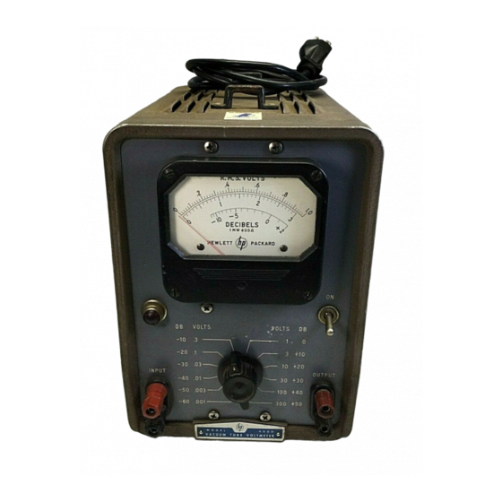
Vacuum tube voltmeter
Hide thumbs
Also See for 400D:
- Operating and servicing manual (50 pages) ,
- Operating and service manual (30 pages) ,
- Service note (11 pages)
Table of Contents
Advertisement
TM 11-6625-1514-15
D E P A R T M E N T O F T H E A R M Y T E C H N I C A L M A N U A L
ORGANIZATIONAL, DS, GS,
AND DEPOT MAINTENANCE MANUAL
HEWLETT-PACKARD
VACUUM TUBE
VOLTMETER
MODELS
400D, 400H, 4001
AND H02-400D
This copy is a reprint which includes current
pages from Changes 1.
H E A D Q U A R T E R S , D E P A R T M E N T O F T H E A R M Y
M A Y 1 9 6 7
Advertisement
Table of Contents

Related Manuals for HP 400D


Summary of Contents for HP 400D
- Page 1 HEWLETT-PACKARD VACUUM TUBE VOLTMETER MODELS 400D, 400H, 4001 AND H02-400D This copy is a reprint which includes current pages from Changes 1. H E A D Q U A R T E R S , D E P A R T M E N T O F T H E A R M Y...
-
Page 2: Dangerous Voltages
WARNING DANGEROUS VOLTAGES EXIST IN THIS EQUIPMENT Be careful when working on the power supplies and their circuits, or on the 230 or 115-volt ac line connections. DO NOT TAKE CHANCES... - Page 3 No. 1 Organizational, Direct Support, General Support and Depot Maintenance Manual HEWLETT–PACKARD VACUUM TUBE VOLTMETER MODELS 400D, 400H, 400L, and H02-400D (NSN 6625-00-643-1670) TM 11-6625-1514-15, 23 May 1967, is changed as follows: 1. Title of manual is changed as shown above.
- Page 5 TM 11-6625-1514-15 SAFETY STEPS TO FOLLOW IF SOMEONE IS THE VICTIM SHOCK OF ELECTRICAL DO NOT TRY TO PULL OR GRAB THE INDIVIDUAL IF POSSIBLE , TURN OFF THE ELECTRICAL POWER IF YOU CANNOT TURN OFF THE ELECTRICAL POWER, PULL, PUSH, OR LIFT THE PERSON TO SAFETY USING A WOODEN POLE OR A ROPE OR S O M E O T H E R I N S U L A T I N G M A T E R I A L SEND FOR HELP AS SOON AS POSSIBLE...
- Page 7 Technical Manual DEPARTMENT OF THE ARMY No. 11-6625-1514-15 Washington, DC, 23 May 1967 ORGANIZATIONAL, DIRECT SUPPORT, GENERAL SUPPORT AND DEPOT MAINTENANCE MANUAL HEWLETT-PACKARD VACUUM TUBE VOLTMETER MODELS 400D, 400H, 400L, AND H02-400D (NSN 6625-00-643-1670) Paragraph Page Section GENERAL DESCRIPTION 1-A.1 1-0.1...
-
Page 8: Illustrated Parts Breakdown
Vacuum Tube Voltmeter 400D/H/L ........ - Page 11 Mail your letter or DA Supply Code 28480) Vacuum Tube Voltmeter Models Form 2028 (Recommended Changes to Publications 400D and H02-400D, serial numbers 310-45571 and and Blank Forms) direct to Commander, US Army higher; and Models 400H and 400L, serial numbers Communications-Electronics Command and Fort 313-22177 and higher.
- Page 13 Accuracy: Model 400D - a. Voltage Range: 400D/H - 0.1 millivolt to 300 volts; 400L - 0.3 millivolt to 300 volts, in 12 ranges ± 2% of full scale, 20 cps to 1 mc;...
- Page 14 1-6. Each model voltmeter has three calibrated scales 1-9. The voltmeter is equipped with a non-detachable on the panel meter. The Models 400D and 400H have power cord. Test leads, which may be plain wire leads two linear VOLTS scales, 0 to 1 and 0 to 3, and one or coaxial cable, and test probes must be supplied by DECIBELS scale, -12 to +2 db.
-
Page 15: Installation
In all other respects the H02-400D is the line voltage from 103 to 127 volts. The reading on the same as the Model 400D and carries the same Federal meter must not change by more than the width of the Stock Number. - Page 16 TM 11-6625-1514-15 Section III Figure 3-1. Voltmeter Front Panel, Showing Controls and Connectors 00102-2...
- Page 17 3-4. METER ZERO CHARACTERISTIC. When the connection can be made without adding the capacity of Model 400D and 400H Voltmeters are turned off, the the user’s hands. meter pointer should rest exactly on the zero calibration mark on the meter scale.
- Page 18 TM 11-6625-1514-15 Section III Paragraphs 3-10 to 3-16 Figure 3-3. Test Setup for Avoiding Ground Loop 3-10. Since the voltmeter meter deflection is propor- setup and watching for a change in meter reading. If tional to the average value of the input waveform, it changing the ground system causes a change in meter is not adversely affected by moderate levels of random reading, ground currents are present.
-
Page 19: Impedance Correction Graph
TM 11-6625-1514-15 Section III Paragraphs 3-17 to 3-21 f. Note the meter indication on the DECIBELS scale (-12 to +2 db). The signal level is the algebraic sum of the meter indication and the db value indicated by the AVOID A SHORT CIRCUIT ACROSS THE POW- RANGE selector. - Page 20 TM 11-6625-1514-15 Section III Paragraphs 3-22 to 3-25 response and calibration of the voltmeter may be + 2 (meter indication) affected by the impedance of a load applied to the +30 (RANGE switch position) OUTPUT terminals. To check the effect of the applied +32 (sum) load: observe the meter reading obtained with no load +8 (correction factor from the Impedance...
- Page 21 TM 11-6625-1514-15 Section III Figure 3-4. Impedance Correction Graph...
-
Page 23: Circuit Description
TM 11-6625-1514-15 Section IV Paragraphs 4-1 to 4-11 SECTION IV CIRCUIT DESCRIPTION 4-6. Cathode follower V1 provides a constant, high input 4-1. BLOCK DIAGRAM. impedance to the input voltage divider and INPUT ter- minals of the voltmeter and provides a relatively low 4-2. -
Page 24: Power Supply
TM 11-6625-1514-15 Section IV Paragraphs 4-12 to 4-16 4-12. During the negative-going half cycle of the plate schematic diagram, figure 5-10. The power supply voltage of V5, rectifier CR2 conducts electrons back to furnishes regulated +250V d-c voltage for the grid and both C32 and C33 from the plate of V5. - Page 25 TM 11-6625-1514-15 Section IV Paragraph 4-17 to within ±1 volt dc as the V7 plate voltage is varied ±10%, the amplifier. The other section supplies a-c voltage for the tubes in the power supply. The voltage required with about 60 ma of load current. The response of the regulating circuits is fast enough to reduce ripple in for the heaters of tubes V1 through V4 is obtained from the output voltage to less than 1 millivolt, supplementing...
-
Page 27: Maintenance
10-db steps, 0 to 70 db. 10-cps to 4-mc range. Oscilloscope or Trouble shooting by H-P 160B or AC Voltmeter signal tracing. H-P 400D Variable Adjust line voltage between 103 Checking voltmeter Transformer and 127V ac with 1-amp load. operation with... - Page 28 TM 11-6625-1514-15 Section V Paragraphs 5-9 to 5-16 c. Rotate mechanical zero-adjustment screw clock- performance check procedure in paragraph 5-22. Re- wise until meter pointer is to the left of zero and mov- sults obtained through the use of a “tube checker” can be misleading.
-
Page 29: Troubleshooting
TM 11-6625-1514-15 Section V paragraphs 5-17 to 5-21 switch assembly. Use the following procedure. (Locate operation by operating the voltmeter at 103 and 127 parts by referring to figures 5-3 and 5-4; RANGE switch line volts while making tests. Check the tubes in the connections are shown in figure 5-9.) voltmeter amplifier. - Page 30 TM 11-6625-1514-15 Section V Figure 5-3. Left Side View of Voltmeter Chassis 00102-3...
- Page 31 TM 11-6625-1514-15 Section V Paragraphs 5-22 to 5-23 Figure 5-4. Right Side View of Voltmeter Chassis a short circuit or partial short in the circuits of the and with low and high line voltages. It can be used for voltmeter amplifier section. A clip-on type milliam- comprehensive incoming inspection, for proof of per- meter should be used for this measurement.
- Page 32 TM 11-6625-1514-15 Section V TROUBLE PROBABLE CAUSE REMEDY 1. Power indicator lamp does not light. a. Fuse F1 burned out. a. Replace fuse F1. If replaced fuse blows, check items 2 and 3 below. b. Power indicator lamp DS1 defective. b.
- Page 33 TM 11-6625-1514-15 Section V Figure 5-6. Test Setup for Calibration Check and Adjustments meter reading; it must not be higher than the residual The residual reading on voltmeter must be no higher than the residual reading obtained with voltmeter INPUT reading noted in step d.
- Page 34 TM 11-6625-1514-15 Section V Paragraphs 5-24 to 5-26 Figure 5-7. Test Setup for Frequency Response Check and Adjustment 5-24. CALIBRATION AND FREQUENCY RESPONSE p. Set voltmeter RANGE switch to .01 and also set the ADJUSTMENTS. frequency response test set OUTPUT ATTENUATOR to .01 to check this voltmeter range: Repeat steps k and m.
- Page 35 TM 11-6625-1514-15 Section V Paragraph 5-27 e. Setting the 20-kc and 4-mc frequency response h. Set the RANGE switch on the voltmeter under test to .001. of the input divider. i. Set the oscillator for 400 cps output frequency and NOTE adjust its output level to obtain a reading at 0.9 on the voltmeter scale.
- Page 37 TM 11-6625-1514-15 Section V Figure 5-9. Diagram of RANGE Switch 5-11...
-
Page 41: Model Number
Vacuum Tube Volt- following the figure and index number in the same column. meters, Models 400D, 400H, 400L, and H02-400D, An explanation of the symbols used is outlined below. manufactured by Hewlett-Packard Co. The breakdown In cases where the “Usable on Code”... - Page 42 TM 11-6625-1514-15 Section VI Paragraphs 6-13 to 6-15 6-13. REFERENCE DESIGNATION INDEX. The Ref- (2) CODE “A1” is applied to assemblies made up of erence Designation Index (Section IX) lists electrical two or more parts each of which carry individual parts by reference designator and is compiled with part numbers and description, and which may be reference designators in alpha-numerical order.
- Page 43 TM 11-6625-1514-15 Section VI NAME AND ADDRESS CODE NAME AND ADDRESS CODE 83330 Smith, Herman H., Inc., 28480 Hewlett - Packard Co., Brooklyn, N.Y. Palo Alto, Calif. Buckley, C. E., 83380 28520 Heyman Mfg. Co., Leominster, Mass. Kenilworth, N.J. 35434 Lectrohm, Inc., Chicago, Ill.
- Page 44 TM 11-6625-1514-15 Section VI H O W U S E T H I S I L L U S T R A T E D P A R T S B R E A K D O W N Numerical Index for that part. If this figure HOW TO FIND THE PART NUMBER IF THE MAJOR shows the part in a major assembly other than ASSEMBLY IN WHICH THE PART IS USED IS KNOWN.
-
Page 45: Group Assembly Parts List
TM 11-6625-1514-15 Section VII Group Assembly Parts List SECTION VII GROUP ASSEMBLY PARTS LIST Figure 7-1. 400D/H/L Vacuum Tube Voltmeter 400D 400D VACUUM TUBE VOLTMETER (28480) . . . 1 7-1- (D) 400H 400H VACUUM TUBE VOLTMETER (28480) . . . 1... - Page 46 S C R E W , M A C H I N E ..- - - * - - - -14 (D, H02) 400D-2 400D-2 PANEL, FRONT (28480) ..
- Page 47 500 µf +100%, -10%, 3 wvdc (56289) (H,L) 0180-0033 30D133A1 CAPACITOR, FIXED, ELECTROLYTIC, . 50 µf, 6 wvdc (56289) 400D-75H 400D-75H BRACKET, CAPACITOR (28480) ..(ATTACHING PARTS) 2390-0009 COML SCREW, ASSEMBLED WASHER, ..
- Page 48 5P-1 -25 (D,H,L) 8120-0050 CS-9941/PH151/ CABLE ASSEMBLY, POWER, ..7.5 FT ELECTRICAL (70903) (H02) H02-400D- H02-400D-PWR- CABLE ASSEMBLY, POWER, ..PWR-CORD CORD ELECTRICAL (28480) CABLE, POWER, ELECTRICAL (70003) (H02) CS-9941/PH151/ 7.5 FT W/O PLUG...
- Page 49 TM 11-6625-1514-15 Section VII Group Assembly Parts List Figure 7-2. Main Chassis Assembly (Sheet 2 of 2) FIG. & MFR. OR MIL DESCRIPTION UNITS STOCK PART INDEX ASSY 7-2-33 1400-0074 INSULOID C3 CLAMP, LOOP (85682) ..(ATTACHING PARTS) 2390-0009 COML...
- Page 50 UNITS MFR. OR MIL DESCRIPTION FIG. & PART INDEX STOCK ASSY PRINTED CIRCUIT BOARD ASSEMBLY 400D-75G 400D-75G 7-2-38 (28480) (See figure 7-4) (ATTACHING PARTS) COML SCREW, ASSEMBLED WASHER, 6-32 by 2390-0009 3/8 in. lg, s.s. - - - * - - - 29C214A3-H-1038 CAPACITOR, FIXED, CERAMIC .
- Page 51 UNITS DESCRIPTION MFR. OR MIL FIG. & INDEX STOCK PART ASSY 7-2-58 400D-65C 400D-65C PRINTED CIRCUIT BOARD ASSEMBLY (28480) (See figure 7-6) (ATTACHING PARTS) 2390-0009 COML SCREW, ASSEMBLED WASHER, 6-32 by 3/8 in. lg, s.s. - - - * - - -...
- Page 52 DESCRIPTION MFR OR MIL FIG. & PART STOCK INDEX ASSY RANGE SWITCH ASSEMBLY (28480) ..400D-19A 400D-19A 7-3- (See figure 7-2, index 32 for next higher assembly) CAPACITOR, FIXED, MICA DIELECTRIC, 0140-0039 CM15E470J 47 pf ±10%, 500 wvdc (MIL-C-5) RESISTOR, FIXED, COMPOSITION, .
- Page 53 TM 11-6625-1514-l5 Section VII Group Assembly Parts List Figure 7-4. Printed Circuit Board Assembly, Part No. 400D-75G FIG. & MFR. OR MIL DESCRIPTION UNITS INDEX STOCK PART ASSY 7-4- 400D-75G 400D-75G PRINTED CIRCUIT BOARD ASSEMBLY . . (28480) (See figure 7-2, index 38 for next...
- Page 54 68 pf ±10%, 500 wvdc (MIL-C-5) 9140-0040 42µH-10%- COIL, RF, 42 µh ±10% (99849) ..PHENOLIC FORM “ PRINTED CIRCUIT BOARD (28480) . . . 400D-75G-1 400D-75G-1 Figure 7-5. Printed Circuit Beard Assembly, Part No. 400D-75F 00102-2 7-10...
- Page 55 RESISTOR, FIXED, FILM, ..40 ohm ±1%, 1/2w (19701) 0686-5115 RC20GF511J RESISTOR, FIXED, COMPOSITION, . . . 510 ohm ±5%, 1/2w (MIL-R-11) 1901-0027 HD-5004 SEMICONDUCTOR DEVICE, DIODE (82577) 400D-75F-1 400D-75F-1 PRINTED CIRCUIT BOARD (28480) . . 00102-2 7-11...
- Page 56 TM 11-6625-1514-15 Section VII Group Assembly Parts List Figure 7-6. Printed Circuit Board Assembly, Part No. 400D-65C UNITS DESCRIPTION MFR. OR MIL FIG. & PART INDEX STOCK ASSY PRINTED CIRCUIT BOARD ASSEMBLY . . 400D-65C 400D-65C 7-6- (28480) (See figure 7-2, index 58 for next higher assembly) CAPACITOR, FIXED, PAPER.
- Page 57 TM 11-6625-1514-15 Section VIII Numerical Index SECTION VII NUMERICAL INDEXES PART NO. NUMERICAL INDEX 00102-3...
-
Page 58: Section Viii Numerical Index
TM 11-6625-1514-15 Section VIII Numerical Index HEWLETT-PACKARD STOCK NO. INDEX 00102-3... -
Page 59: Reference Designation Index
TM 11-6625-1514-15 Section IX Reference Designation Index SECTION IX REFERENCE DESIGNATION INDEX 0 0 1 0 2 - 3 9 - 1... - Page 60 TM 11-6625-1514-15 Section IX Reference Designation Index 00102-1...
- Page 61 TM 11-6625-1514-15 Section IX Reference Designation Index 00102-1...
-
Page 63: Auxiliary Equipment
TM 11-6625-1514-15 SECTION X AUXILIARY EQUIPMENT 400-series Vacuum Tube Voltmeters, or similar 10-1. General equipment, for carrier currents or other meas- 10-2. Auxiliary equipment extends the opera- urements between 5 Kc to 600 Kc. With a tion of the basic equipment, is not part of the Model 200CD it provides fully balanced 135- basic equipment, and is not required for normal or 600-ohm output with attenuator in use. - Page 64 Use 10 K position when bridging a bal- the line. anced system for measurements with single The Models 200CD and 400D may be used ended instruments such as the H-P Model in conjunction with the Model 11004A to form...
- Page 65 TM 11-6625-1514-15 Table 10-2. Specifications Distortion: Less than 0.1%, 50 cps to 20 Kc; Frequency Range: 20 cps to 45 Kc. Less than 0.5%, at 20 cps. Impedance, Primary: 600 ohms. Balance: Better than 60 db. Terminating Resistance: 600 ohms or 10,000 ohms. Maximum Level: +15 dbm (4.5 volts at 600 ohms).
- Page 66 TM 11-6625-1514-15 Figure 10-2. 11004A line matching transformer, Figure 10–4. Typical measurement setup. schematic diagram. Figure 10-3A. Typical bridging type of 600-ohm setup showing balanced to unbalanced line confirmation. Figure 10-5. Signal generator setup. Figure 10-3B. Typical setup showing unbalanced to 135-ohm balanced line configuration.
- Page 67 Line Matching Transformer HP-11004A. loss. (1) Connect Generator HP 200 CD and Voltmeter HP 400D to the secondary of the (4) Repeat the test in the range between 5 KHz and 600 KHz. The reading should not vary more than transformer.
- Page 69 HEADQUARTERS DEPARTMENT OF THE ARMY , D.C., 23 May 1967 ASHINGTON TM 11-6626-1514-15 is published for the use of all concerned. By Order of the Secretary of the Army: HAROLD K. JOHNSON, General, United States Army, Chief of Staff. Official: KENNETH G.
- Page 72 PIN : 019300-000...