Table of Contents
Advertisement
Perkins Electro-Acoustic Research Lab, Inc.
Please note that the links in the P
and can be used to direct your web browser to our site or to
open an e-mail message window addressed to ourselves.
To see the feedback we have left for our customers,
This document has been prepared as a public service . Any and all trademarks
and logotypes used herein are the property of their owners.
It is our intent to provide this document in accordance with the stipulations with
respect to "fair use" as delineated in Copyrights - Chapter 1: Subject Matter and
Scope of Copyright; Sec. 107. Limitations on exclusive rights: Fair Use.
Public access to copy of this document is provided on the website of Cornell Law School
at
http://www4.law.cornell.edu/uscode/17/107.html
Notwithstanding the provisions of sections 106 and 106A, the fair use of a copyrighted work, includ-
ing such use by reproduction in copies or phono records or by any other means specified by that section,
for purposes such as criticism, comment, news reporting, teaching (including multiple copies for class-
room use), scholarship, or research, is not an infringement of copyright. In determining whether the use
made of a work in any particular case is a fair use the factors to be considered shall include:
1 - the purpose and character of the use, including whether such use is of a
commercial nature or is for nonprofit educational purposes;
2 - the nature of the copyrighted work;
3 - the amount and substantiality of the portion used in relation to the copy-
righted work as a whole; and
4 - the effect of the use upon the potential market for or value of the copy-
righted work.
The fact that a work is unpublished shall not itself bar a finding of fair use if such finding is made
upon consideration of all the above factors
Web:
http: // www. pearl - hifi . com
E-mail:
custserv @ pearl - hifi . com
Inc.
To view our item listings on eBay,
Sec. 107. - Limitations on exclusive rights: Fair Use
♦
86008, 2106 33
Ph: + .1.403.244.4434
❦
Engineering and Intuition Serving the Soul of Music
logotype above are "live"
EARL
click here.
and is here reproduced below:
PDF Cover Page
♦
Ave. SW, Calgary,
AB; CAN T2T 1Z6
Fx: + .1.403.245.4456
click here.
Advertisement
Table of Contents
Troubleshooting

Related Manuals for HP 400F


Summary of Contents for HP 400F
- Page 1 Web: http: // www. pearl - hifi . com Ave. SW, Calgary, 86008, 2106 33 AB; CAN T2T 1Z6 Ph: + .1.403.244.4434 Fx: + .1.403.245.4456 E-mail: custserv @ pearl - hifi . com Inc. ❦ Perkins Electro-Acoustic Research Lab, Inc. Engineering and Intuition Serving the Soul of Music Please note that the links in the P logotype above are “live”...
- Page 2 Verso Filler Page ♦ ♦...
- Page 3 400F/FL AC VOLTMETER OPERATING SERVICE MANUAL � HEWLETT PACKARD...
- Page 4 CE RTI FI CATION The Hewlett-Packard Company certifies that this instrument was thoroughly tested and inspected and found to meet its published specifications when it was shipped from the factory. The Hewlett Packard Company further certifies that its calibration measure ments are traceable to the U.S.
- Page 5 OPERATING AND SERVICE MANUAL (HP PART 00400-90005) MODEL 400F/FL VOLTMETER SERIALS PRE FIXED: 734- Appendix C. Manual Backdating Changes. this 617-. adapts manual to serials prefixed 1966 Copyright Hewlett-Packard Company 301. 80537 U. S. A. P. O. Box Loveland, Colorado,...
- Page 6 Verso Filler Page ♦ ♦...
-
Page 7: Table Of Contents
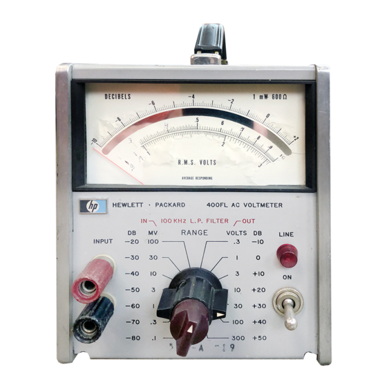
5-3. Input Impedance Check Setup ..3-3. 5-4. Location Internal Adjustments Impedance Correction Graph ..6-1. Model 400F/FL Range Switch and plo 4-1. Functional Circuit Diagram Internal Wiring Data ..4-2. Filter Attenuation Characteristics . - Page 8 Section I Model 400F / FL Figure 1-1. ModeI400F/FL AC Voltmeter Table 1-1. Specifications -hp- Model 400F /FL -hp- Model 400F /FL lOO Jl < Voltage Range: V to 300 V full scale. 14 Recovery From Overload: 2 seconds for 80 dB overload.
-
Page 9: General Information
Model 400F /FL described in this manual. 400F /FL in reference to both instruments. 1-8. a letter prefixes the serial number, the 1-3. - Page 10 Mot.!cI4IXJ1·/I· Sectioll l M,u.lln'Jm O�fllrJ.ad AC lOUoI!jt" mpt.lt tu ,�n"WolH' mV ttm)IJ'1Ih 300 m" 'oI'l\ln thl' mu\I Ol:tttJ th. �.aI\J" ,huwn �OO • � > � 401( 201( _00' .." FREOUENCY (Ht) 1 V II'I,o�h 300 V "flgU "._np, ...
-
Page 11: Section Installation
-hp- Sales and Service Office. (See 2-5. POWER REQUIREMENTS. AppendLx B for office locations.) 2-6. The Model 400F/FL can � operated from any the instrument is to be shipped source of 115 or 230 volts at 50 to 1000 cycles or... -
Page 12: Location Of Controls And Indicators
, ..�� .. r"" • �: 400'/fl-B-Q839A Primary Power Connector:· Line voltage is ap� 400F Scale: [ndicates magnitude of applied sig nal in volts and dBm. plied through this connector. ® Mechanical Zero Adjust: Provides a mechanical FUSE: Protects instrument against current meter zero adjustment. -
Page 13: Operating Instructions
BATTERY VOLTAGE 3-2. This section contains instructions and information 35-55 35-55 necessary for the operation of the 400F/FL AC Volt meters. Included is identification of controls� indi cators and connectors. turn on proceduresiand oper ating instructions. 3-3. CONTROLS, INDICATORS AND CONNECTORS. -
Page 14: Wide Band Ac Amplifier
GAIN the actual dB measurement is +17 dB. 300 V -50 dB lOOmV +20 dB The dB scale of the 400F/FL is calibrated 100 V -40 dB 30mV +30 dB in dBm. 0 dBm is equivalent to 1 milliwatt 30 V... -
Page 15: Impedance Correction Graph
Section Model F /FL +1 5 � Il:: Il:: Il:: � lOOK IMPEDANCE OHMS 400E/EL4-0471 Figure Impedance Correction Graph 3-3. 01795-1... - Page 16 Section IV ModeI400F/FL Figure 4-1 � " % • . � -t> - - - 01795-1...
-
Page 17: Theory Of Opera Tion
4-12. Feedback from the emitter of A2Q2 bootstraps thevalueofA2R9. the drain load of A2Q1. Feedback 4-2. The 400F/FL is a801id state. average responding. from the source of A2Q1 bootstraps the input impedance rms calibrated ac voltmeter. It may also be used... -
Page 18: Meter Amplifier
ModeI 400F/FL Section IV Paragraphs 4-17 to 4-25 and Ftgure 4-2 independent current source which will supply a signal 4-17. METER AMPLIF1ER. to the OUTPUT terminal that is identical to the signal applied to the meter bridge. 4-18. The meter amplifier is a four stage, direct That is. -
Page 19: Power Supply
A2Q6, which wUl supply a signal indicated in db, but not dbm. The meter is protected proportional to the change in output voltage A2Q5. circuit overloads by diode CRI (400F) and A2Q5 will then amplify the signal and couple it from capacitor Cl (400FL). -
Page 20: Test Equipment
Table 5-1 and Figure 5-1 Table 5-1. Test Equipment RECOMMENDED INSTRUMENT REQUIRED MODEL TYPE CHARACTERISTICS Performance Checks -hp- Model 738BR Volt- AC Voltmeter Accuracy: 0.2% at 400 Hz meter Calibrator Calibrator Range: 30 mv to and Calibration Output: Performance Checks... -
Page 21: Top Cover Removal
5-6. The following Performance Checks compare the 400F/FL withits accuracy specllicaUons (Table 1-1). Set 400F/FL RANGE switch to 30 mv, and set These checks may be used for incoming inspection, 100 KHz F1LTER switch to OUT. Set switch periodic maintenance, and for specification checks 51 to Position A. -
Page 22: Full Scale Calibration Tolerances (400F)
Adjust test oscillator set for a 30 mv output Adjust test oscillator for a 1 volt output at at 400 Hz, using as a reference the 400F/FL 400 Hz using as a reference the 400F/FL meter indication obtained in step d of this meter indication obtained i n step h of this paragraph. -
Page 23: Input Impedance Check
400F should indicate 30 mv :5%. less on the volt range. 2) 400F/FL cannot be checked with a 1/10 Set 400F/FL RANGE switch to 300 my . . scale input. Set frequency response test set output for full scale deflection 400F/FL meter at 400 Hz. -
Page 24: Cover Removal And Replacement
Figure 5-3. Input Impedance Check Setup 5-24. SIDE COVER. specifications. The following procedures specify the use ol an -hp- 736BR Voltmeter Calibrator and an -hp- 652A Test Oscillator. However, an -hp- K02-736BR 5-25. Remove the lour screws from side cover, and lift off. -
Page 25: Meter Calibration
1 volt. If more than a 1% adjustment is Adjust A2R59 for a 400F / F L m e t e r needed. repeat the 400 Hz adjustment. indication o f 30mv. Set test oscUlator to 4 MHz. maintaining am... -
Page 26: Preamplifier
-17. 0 v :t2. 0 v section should be made with the Collector Q2 7. 5 v ±Q. 5 v 400F /FL input shorted and the RANGE Collector Q3 -21. 4 v :t1 . 0 v switch set to 1 volt. - Page 27 Fl'lE?3 Clip excess leads oH after soldering and clean excess flux from the connection and adjoining EXCESSIVE OR PROLONGED HEAT area. using type TF Freon (-hp- Part No. CAN UFT THE CIRCUIT FOIL 8500-0232). 01795-1...
- Page 28 Verso Filler Page ♦ ♦...
-
Page 29: Schema Tic
Model 400F/FL Section Paragraphs S E C T I O N S C H E M A T I C S 6 - 1 . I N T R O D U CT I O N . the component location on the printed cir... -
Page 30: Model 400F/Fl Range Switch And Plo Internal Wiring Data
.•.. • • . I •..• • · • • • . . . { ' .. � DETENT BOTTOM VIEW 400F/FL-B-OI41 6-1. Model 400F FL Range Switch and plo Internal Wiring Data Figure 01795- 1... - Page 31 3-RED/VEL II-GRN 15-BLK WIRE COLOR WHT /RED 12-WHT 4-WHT /RED/VEL 16-VIO Part 00400-66504) A2 BOARD (-hp- � Part 00400-66505) Al BOARD (-hp- A I C 2 A2R58 A2R6 2 A2R59 A2C36 01795- 1 Figure 6-2. Model 400F /FL Component Location...
- Page 32 • " 50 604 0.02 R 65 � � 2.�MH BATTERV )>- ...; : - --------...: � = O :::. . ( VOLTAGE R 3I 6 8.1 Figure 6-3. COPYRIGHT 1966 BY HEWLETT-PACKARO COMPANY Schematic Diagram Model 400F/FL 01'1.15-1 6-3/6-4...
- Page 33 Verso Filler Page ♦ ♦...
-
Page 34: Location Of Important Mechanical Parts
Mode1400F/FL Section Figure �@�� ® 40QF/Fl-B-O'''O M P 7 MPI7 @@@ @ @®@@ 400F/FL-RO MP2 7 MP26 � �' " MP25 Figure 7-1. Location of Important Mechanical Parts 01795-1... -
Page 35: Ordering Information
7 - 4 . O R D E R I N G I N F O R M A T I O N . meric order of their reference designators and indi each cates the description, -hp- part number 7-5. To obtain replacement parts, address order or... - Page 36 Section VD ModeI 400f'/f'L Table 7-1 Table 7-1. Replaceable Pans -hp- REFEREI'CE MFR_ MFR. PART NO. DESCRIPTION DESIGNATOR PART 00400-66505 Assembly: board etched circuit includes 28480 00400-66505 Cl through C6 Kt through K2 R I through R7 AICI 0150-0012 Cxd cer 0.01 J--L f: :t20% 1000 vdcw...
- Page 37 Model 400F/FL Section Table 7-1 Table 7 - 1 . Replaceable Parts (Cont'd) 1'0. -h p- MFR. MFR. PART DESCRIPTION PART NO. DI:: S ICNATOR A2C27 0150-0122 801-000-Y55-202M fx.d 002 j.ll :1:20% 500 vdcw 72982 A2C28 fx.d 130 mica :1:5% 300 vdcw...
- Page 38 Section Model 400F/FL Table 7-1 Table 7-1. Replaceable Part::; (Cont'd) -hp- REFERENCE MFR. MFR. PART DESCRIPTION DESIGNATOR PART NO. A2R9 0757-0434 [xd prec met !1m 3. 65 K ±I% 1/8 w 91637 MFF-1/8 T-O ob<! A2RIO 0698-3510 fxd prec met tlm 453 ohms il% 1/8 w 91637 MFF-1/8 T�O...
- Page 39 MFF-l/8 T-O (400FL Only. A2R75) 150D606XOO6B2 0180-0106 f x d Ta 60 Ilf ::1:20% 6 vdcw (400FL Only) 56289 Diode: Si (400F Only) 30 ma at +10 v piv 12 07910 CD6319 obe! 1901-0040 pf 2 ns 1450-0048 Lamp: pilot A165 red transparent...
-
Page 40: Replaceable Parts
Model 400F/FL Section Table 7-1 Parts (Cont'd) Table 7-1. Replaceable -hp- REFERENCE DESCRIPTION MFR. MFR. PAnT NO. DESIGNATOR PART NO. SIRl 0757-0167 hd prec 143 ohms :tl% 1/4 w 19701 MF6C T-O StR2 through :to. S1R6 0698-4118 f.xd met flm prec 277. 48 ohms... -
Page 41: Code List Of Manufacturers
ModeI 400F/FL Appendix A APPENDIX CODE LIST OF MANUFACTURERS (Sheet 1 of 21 The lollowing eode numben; are Irom the Federal Supply Code for Manuladuters Cotologing Hondbooh H4.1 (Nllme to C (Code to Nomel and their lated sup p lements. The date o f revision ond the dilte the supplements used IIppeor ot ... - Page 42 400F/FL Model Appendix A APPENDIX CODE LIST OF MANUFACTURERS (Shee t 2 of 21 .uo..� ..� ..,,, .. co . J. • .•. IH r .. ,,-. C.�. ",1'1 C . , . e-,.."...
- Page 43 Appendix ModeI 400F/FL H E W L E T T PA C K A R D S A L E S A N D S E R V I C E O F F I C E S t h e...
- Page 44 Appendix ModeI 400F/FL H E W L E T T - P A C K A R D I N T E R N AT I O N A L O F F I C E S E l e c t r o n i c...
- Page 45 Appendix C \lodel400F/FL 'MANUAL BACKDATING CHANGES Model Name Prefil< mSlrlllllents. This manual b3�kdating sheet lIIakes this manual appli�able earlier arc not ImUUmCIII1:0mpc1llent values that dif' from those in the manual, yet listed in given the �'�kda!ing sheet, should be rcpla�\. .!ng the part number in the Innu31.
- Page 46 MP26 SO(}()'0711 Cuver Ass)': buttolll MPJO 0Q4 QO.()O 207 Panel: front (400Fl) A2R63, 0757-0417, R:fxd prcc Ilm 562 n 1 % IISW 004 QO.()O 208 (400F) Panel: frulIl meler MP 31 S02(}'0704 Trim: (400FL) meter CflANGE NO. 5 503 (}'S388...
- Page 47 MANUAL CHANGES MIm,I for Modtt Mlmbrr 400F/FL prlntflt ..1 July 1974 00400-90016 Nu., MnlIl ,. Make.n ERRATA comctlont. a.ectc · the following prefbr/aeri.ll'll rnber table 'Of' your Instrument ..1 and make mInU... the tilted changes to your ·...
- Page 49 M)OEl 400F IFl . · MANUAL CHANGE I On Table 6-1. change the Table of Replaceable Parts to read� Aiel 0160-2902 C:FXO (ER O.OlUF 201 lOOO V AIC2 0132-000 3 C:VAA TRltHR 3�� AICl.6 0160-2930 C:FXO UR a.OIUF +80 -201 lOOV...
-
Page 50: Replaceable Parts
MODEL 400F /fL . HAHUAL CHANGE 3 On Table 6-1, change the Table of Replaceable Pa r t s re ad: MP24 PANEL ASSr REAR 00400-60212 DELETE MPl,2,3,4.6,7,12,13 0340-0732 INSULATOR BINDING POST 1510-0084 BINDING POST 1510-0087 BINDING POST 1510-0090 BINDING POST 1510 .. - Page 52 Pig' 7-317-4, Flgur. 7·2. O1angQ A2 board from ·hp- number 0Q400-66504 0040()'66514. CHANGE NO. 6 tppll,s lerllll numbers OQSOA1"'Z06 and .bov. for the 400F .nd le,t.1 numbers 0950Al0176 and lbov. for the 400FL. part P";I change 6-4, A2C38, C39 from ;hp·...
- Page 54 PACKARD HEWLETT Printed in U.SA. 00467-90003...