Table of Contents
Advertisement
Quick Links
Advertisement
Table of Contents

Related Manuals for Motorola RP Series


Summary of Contents for Motorola RP Series
- Page 1 RPX Repeater Series Installation and User Guide Model RPU2160...
- Page 2 No duplication or distribution of this document or any portion thereof shall take place without the express written permission of Motorola. No part of this manual may be reproduced, distributed, or transmitted in any form or by any means, electronic or mechanical, for any purpose without the express written permission of Motorola.
-
Page 3: Table Of Contents
CONTENTS Pre-Installation Considerations ..10 RF Coverage Field Test... . . 10 Computer Software Choosing a Tentative Location ..11 Copyrights . - Page 4 Installing External Antenna Getting Started ..... . 33 Using the Antenna/Magnetic Turning Repeater On/Off ....33 Mount/RF Cable Kit Accessory .
- Page 5 Series™ System....68 Motorola Limited Warranty AC Line Requirements: ... . . 68 for the United States .
-
Page 6: Computer Software
Accordingly, any copyrighted Motorola computer programs contained in the Motorola products described in this manual may not be copied, reproduced, modified, reverse-engineered, or distributed in any manner without the express written... -
Page 7: Radio Frequency (Rf) Exposure Safety Standards
RF energy awareness information contained in the C a u t i o n For a list of Motorola-approved antennas and other Product Safety and RF accessories, visit the following web site which lists Exposure booklet (Motorola... -
Page 8: Operational Safety Guidelines
OPERATIONAL SAFETY GUIDELINES Protect the power cord from being walked on or pinched particularly at plugs, convenience Read these instructions. receptacles, and the point where they exit from the apparatus. Keep these instructions. Use only the attachments/accessories specified Heed all warnings. by the manufacturer. - Page 9 Disconnect the power supply from the line voltage by removing the main plug. The outlet to which this equipment is connected should be nearby and easily accessible. Maximum ambient temperature around the power supply equipment must not exceed 40 °C (104 °F).
-
Page 10: Fcc Licensing Information
The RPX Repeater Series™ operate on radio FCC LICENSING frequencies that are regulated by the Federal INFORMATION Communications Commission (FCC). To transmit on these frequencies, you are required to have a license INTERFERENCE INFORMATION issued by the FCC. Application is made available on FCC Form 601 and Schedules D, H, and Remittance This device complies with Part 15 of the FCC Rules. - Page 11 Changes or modifications not expressly approved by intended to be distributed is subject to government Motorola may void the user’s authority granted by the regulations and may be prohibited. FCC to operate this radio and should not be made. To...
- Page 12 Notes...
-
Page 13: Introduction
Congratulations on your Motorola® RPX Repeater • Repeater (includes the Alkaline Battery Frame) Series™ purchase! • Antenna This repeater is a product of Motorola's 80 plus years • Power Supply of experience as a world leader in the designing and • Wall holster mount manufacturing of communications equipment. -
Page 14: About This Manual
MOL (Motorola On-Line Tool). RF: Radio Frequency For all other inquiries about service information, P/N: Part Number please call your Motorola Point of Contact or call: 1-800-448-6686 in the USA Table 1: RPX Repeater Series™ Models 1-866-522-5210 on your TTY (Text Telephone) -
Page 15: Repeater Overview
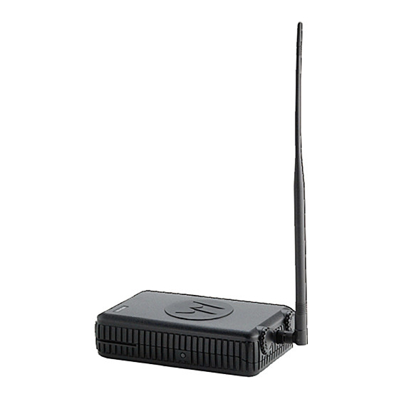
REPEATER OVERVIEW PARTS OF THE REPEATER Antenna Connector Channel Status LED Knob ON/OFF Indicator Knob Battery Frame Programming Connector Model Label Power LED DC/AC Indicator Connector Dipole UHF Antenna AC/DC Power Supply Wall Mount Figure 1. Repeater Parts Note: The RPU2160 repeater model comes with a standard Alkaline Battery Frame. A Li-Ion Battery Frame is also available as an optional accessory (P/N HKHN4004). - Page 16 For RDX radio model information details, please contact your The side LED indicator gives repeater AC/ Motorola Point of Sale. DC connection status whenever the repeater is working on alkaline Battery Frame On/Off Knob (standard repeater model).
-
Page 17: Repeater Accessories
The repeater offers the convenient capability of customizing your repeater features by using the CPS (Computer Programming Software). Please refer to the "Programming The Repeater” on page 38 for more information. For Software download information, contact your Motorola Distributor or Reseller. - Page 18 Repeater General Applications The repeater operates in the UHF 450 – 470 MHz (with TX/RX 10 MHz separation) band providing The repeater is ideal as a range extender, that 16 channels with different pre-programmed can help reach other users in areas that are settings.
- Page 19 Note: (1) The repeater works best when located in an ideal place that can have good reception for re-transmitting the signal without any problems. Refer to "Pre-Installation Considerations” on page 10 for more information. (2) The repeater is manufactured to MIL SPEC 810 C, D, E and F and G and IP55, makes it robust enough to meet stringent specifications for shock, rain, humidity and salt fog, vibration,...
-
Page 20: How The Repeater Works
How the Repeater Works In the Figure 3a, the repeater gets the signal “X” that Paul transmits from his radio and converts it The repeater allows 2-way radios, base stations or into a “Y” frequency that re-transmits to Tom. In call boxes to communicate through the repeater in Figure 3b, when Tom answers back to Paul, his order to extend the coverage range and/or... - Page 21 The following are estimations of the repeater’s talk As seen in Figure 4, the maximum antenna height coverage range: for low power fixed stations is limited to 23 meters (75 feet) above ground. For stations operating at fixed locations for temporary periods, the antenna Table 2: Inside Building Talk Range height is limited to 7 meters (20 feet) above Model...
-
Page 22: Pre-Installation Considerations
RF Coverage Field Test PRE-INSTALLATION CONSIDERATIONS The following instructions* are quick and easy tips to test the RF coverage area and decide the best Proper repeater installation ensures the best position for the Repeater Antenna (either with the possible performance and reliability of the antenna directly installed into the repeater device repeater. -
Page 23: Choosing A Tentative Location
Choosing a Tentative Location • If you are planning to use the repeater to cover a large area with different buildings, it is Prior to the RF coverage field test, you must first strongly recommended that you use the decide which would be the tentative locations for the repeater. -
Page 24: Conducting The Rf Coverage
Conducting the RF Coverage Field Test The objective of the field test is to “simulate” the transmission quality and coverage that the repeater may have based upon a chosen location. This type of testing and planning becomes very useful as it can save you extra work and money as a poor location and/or adverse environmental conditions can affect the repeater’s performance. -
Page 25: Environmental Conditions At Intended Installation Site (*)
During this RF test coverage, try to test those For information on how to set up and program spots that are most likely to be used for most of multiple repeaters in the same area (for different the people and those areas that may appear user groups), please refer to the "Setting Up particularly challenging due to concrete/steel Multiple Repeaters In A Single Location (Multiple... -
Page 26: Temperature Ranges
Temperature Ranges Note: The repeater is a IP55 water resistant device, able to withstand water exposure for This is the temperature measured in close certain periods of time. Bear in mind that the proximity to the repeater. For example, if the repeater is NOT a submersible device. -
Page 27: Electrical Requirements
ELECTRICAL REQUIREMENTS Note: The AC socket must be installed near the equipment and must be easily accessible. AC/DC Power Requirements Consideration should be given to the connection of the equipment to the supply The repeater comes equipped with a AC/DC circuit and the effect that overloading of the power supply, that operates from 110 Vac to 240 circuits might have on over current... -
Page 28: Electrical Ground
Note: Motorola recommends the following RF Ground reference source: “Motorola Quality This type of ground is related to the transmission Standards Fixed Network Equipment of the radio frequency energy to earth ground. -
Page 29: Repeater Installation
REPEATER INSTALLATION For the explanations in this chapter, please refer to the “Parts of the Repeater” on page 3 under “Repeater Overview” for more information. Installations Considerations The repeater is suitable for any location where operations will meet the environmental conditions Figure 6. - Page 30 Similarly, when using an external antenna (Antenna/Magnetic Mount Kit – P/N HKKN4022), make sure that there is a minimum of 2 to 3 feet distance for both the power cable and RF cable to Power Supply run straight from the repeater in order to assure Cable that performance is not deteriorated.
-
Page 31: Antenna Installation Instructions
Repeater Important tighten it completely. Otherwise, it cannot stand upright. The approved Motorola antenna for the RPU2160 is the UHF Dipole Antenna P/N HKAE4000 (50 Ohm). (Installing the dipole antenna directly onto the repeater is recommended whenever coverage... - Page 32 Make sure the dipole antenna is mounted vertically (90 degrees) in reference to earth ground (either up or down). Please refer to “Figure 9. Examples of Correct Dipole Antenna Orientation” on page 20 and “Figure 10. Examples of Incorrect Dipole Antenna Orientation”...
-
Page 33: Installing External Antenna Using The Antenna/Magnetic Mount/Rf Cable Kit Accessory
Installing External Antenna Using the Note: Always use Motorola approved accessories in order to assure performance and safety. Antenna/Magnetic Mount/RF Cable Kit Please refer to “Accessories” on page 61 for Accessory details. If as an outcome of the RF Coverage Test Field, Magnetic Mount Kit Installation (please refer to “Pre-Installation Considerations”... - Page 34 • Make sure the exterior antenna magnetic mount is installed and positioned away from obstructions like metal structures, concrete walls or any other objects that may cause signal shielding. 90º Ground Figure 11c. Examples of Incorrect Exterior Magnetic Mount Antenna Orientation 90º...
-
Page 35: Rf Cable Installation
RF Cable Installation When installing the RF cable make sure that: Note: The RF cable is 12 feet long. Keep this in • The RF Cable is taut. mind when locating the repeater. • The RF Cable doesn’t go around the magnetic In order to attach the RF Cable to the Repeater mount antenna, antenna, the repeater device (please refer to “Figure 12. -
Page 36: Installing Exterior Antenna
Installing Exterior Antenna Uninstalling Exterior Antenna In order to install the exterior antenna into the Turn counterclockwise in order to remove antenna from magnetic mount. magnetic mount, simply: Align the threaded end of the antenna with the magnetic mount’s mini UHF connector as It is important that all antenna cables shown on “Figure 13. - Page 37 The repeater comes from the factory with the wall mount attached to the repeater. Detach it by pushing out the bottom tab as shown in Figure 14b Remember not to install the repeater on below: or near conductive or shielding Important surfaces.
-
Page 38: Ac/Dc Power Supply Connection
AC/DC Power Supply Connection Each repeater ships standard with an AC/DC Slide the repeater down into the wall Power supply cord (P/N PMPN4002A)(9 feet mount long) that connects the repeater to a (110/120)/ (220/240) Vac source. Note: The AC/DC power supply cable is not suitable for outdoor use. -
Page 39: Vehicle Charger
Vehicle Charger To connect AC/DC power supply: The repeater offers the convenience of a Plug the AC/DC power supply into an AC Vehicle Charger accessory (P/N HKPN4003, power source of 110/220 Vac or a 12 VDC sold separately). power and route it to the Repeater Jack labeled “AC/DC IN”. -
Page 40: Repeater Installation - Example
Repeater Installation – Example Note: This configuration example assumes that the repeater is working on back-up The following repeater installation example in • batteries. (The power supply is not designed “Figure 15b. Repeater Installation Example” for outdoor use). on page 28, shows the magnetic mount and RF cable installed on top of the car’s roof in order to secure the exterior antenna against wind and allow repeater to be placed inside... -
Page 41: Alkaline Battery Frame
ALKALINE BATTERY FRAME ABOUT ALKALINE BATTERIES Please visit your Alkaline batteries’ manufacturer website for information and guidelines regarding handling and disposal of Alkaline batteries Do not store alkaline batteries in a non- Figure 16a. Alkaline Battery Frame operating equipment for longer than 30 Important days. -
Page 42: Alkaline Battery And Power Detection Led (Side)
Alkaline Battery and Power Detection LED (Side) Do not attempt to recharge alkaline batteries. They are non-rechargable. Important The Alkaline Battery Power LED on the side of the repeater gives you status on the external power connection and indication on whether or not the batteries are being detected (as long the repeater is getting AC/DC power). In the case that the repeater loses the external AC/DC power, this LED goes OFF. -
Page 43: Installing/Removing The Alkaline
Installing/Removing the Alkaline Use a Phillips screwdriver to remove the four corner screws located at each corner on the Battery Frame back of the repeater, disconnect power Ensure that the wall mount holster is harness and lift away the repeater back detached from the repeater. -
Page 44: Li-Ion Battery Frame (Optional Accessory)
Arrange alkaline batteries to match each of Assemble the alkaline battery frame (loaded the alkaline frame batteries’ polarity (+ or -) with the alkaline batteries) into the back of markings and slide them into each one of the the repeater by tightening securely the four alkaline battery frame compartments. -
Page 45: Getting Started
Radio LED Indicators GETTING STARTED TURNING REPEATER ON/OFF Repeater Front LED (Status Indicator) Table 4: MODE LED STATUS Never transmit without having a transmit antenna connected to the TX C a u t i o n antenna jack of the repeater. Transmitting/ Solid Red Receiving... - Page 46 Repeater Front LED (Status Indicator) Table 4: (Continued) MODE LED STATUS Low Battery Orange (Fast) Shutdown Blinking Orange Low Battery Blinking 1 Green Blink, Fatal Error at 1 Orange Blink, Power Up 1 Green Blink, then repeat Unprogrammed Double Red Channel (Slow) Blinking 1 Red Blink, 1...
-
Page 47: Selecting A Channel
SELECTING A CHANNEL pre-programmed Frequency, Interference Eliminator Code and Bandwidth Settings. Please The repeater offers 16 different channels from refer to the following table for factory default which you can choose ONE channel at a time for values details: the repeater to operate. To select a channel, rotate the Channel Selector Knob until you reach the desired channel. - Page 48 Table 5: Repeater Channels Default Settings (Continued) Transmit Band Receive Band Common Parameters 450 – 455 MHz 465 – 470 MHz Channel Code Frequency Frequency Frequency Frequency Code Value Bandwidth (RX) Index (RX) MHz (TX) Index # (TX) MHz (Index #) (Hz) 452.4125 179.9...
-
Page 49: Repeater Programming Default
REPEATER PROGRAMMING DEFAULT VALUES Table 6: Programmable Features Default Values "Programmable Features Default Values" on Feature Values Default page 37 shows the default factory values that the repeater has pre-programmed. These values can TX Timeout 1, 2 or 3 minutes 1 minute only be customized by using the CPS software. -
Page 50: Programming The Repeater
Please refer to the CPS software HELP File PROGRAMMING THE (under “Content and Index”) where you can find REPEATER the details and explanations for each one of the repeater’s programmable features PROGRAMMING FEATURES OVERVIEW The repeater is a fully programmable device that provide features customization by using the CPS (Computer Programming Software). - Page 51 Figure 18. Example of the CPS Repeater Interface Note: Contact your Motorola distributor or reseller in order to get information on how to get a copy of the CPS software. User Guide...
-
Page 52: Programming The Repeater
Programming the Repeater Using the Before you begin programming the repeater make CPS Programming sure you have available: Cable • A PC ( Windows® XP, Windows 2000 compatible, Vista) To computer USB Port • CPS Programming Cable (sold separately as an accessory P/N RKN4155), To repeater programming... -
Page 53: How To Read And Modify Your Repeater's Features
How to Read and Modify Your When the CPS reads the repeater successfully, you can see a window pop up Repeater’s Features showing a bar progress icon indicating the repeater’s profile is being read. Ensure you have installed the latest CPS in Note: You can now read and modify all your your computer. - Page 54 CPS Connection Troubleshooting Table 7: Programming Mode: Troubleshooting Symptom Try This CPS doesn’t read the Make sure the CPS cable is securely connected on both ends repeater or write to the (programming port in the repeater and USB port in the computer). Make repeater sure your repeater hasn’t run out completely of battery power or it is connected to an AC/DC supply.
-
Page 55: Programming Your Radios
(*) For RDX repeater capable models, please refer to 2-Way RDX Repeater Capable UHF Radios on page 62. For more information, please contact your Motorola Point of Purchase or call: 1-800-448- 6686 in the USA 1-866-522-5210 on your TTY (Text Telephone) - Page 56 • Make sure the channels in both the RDX radio and the repeater that you want to use with the repeater capability are actually enabled in the CPS with a “check” box looking as follows: Figure 20. Enabling Repeater capability settings User Guide...
- Page 57 • Make sure the TX frequency and PL Code in Note: Take into account that when matching channel frequencies between the repeater the radio channel that has been chosen for and the radios, you must also need to make repeater, is the same as the RX frequency in sure all other channel parameters (i.e.
-
Page 58: Programming Multiple Repeaters
Additionally, in order to minimize the interferences PROGRAMMING MULTIPLE in the multi-repeater system (due to inter- REPEATERS modulation) you can follow these optional configuration recommendations: SETTING UP MULTIPLE REPEATERS IN A SINGLE LOCATION (MULTIPLE The repeaters should be physically separated at USER GROUPS) least 5 feet apart from each other. - Page 59 When choosing frequencies in either the TX or When configuring three or more repeaters (with RX band, take into account to have a minimum different channels), it is recommended to have separation of 100 kHz between frequencies in an asymmetrical separation between the the same band (See Figure 21).
-
Page 60: Repeater Cloning
REPEATER CLONING RDX RADIO TO REPEATER CLONING To repeater programming connector R2R Cloning Cable To RDX radio charger mini-port connector Figure 22. Cloning from an RDX radio into the Repeater User Guide... -
Page 61: Operating Instructions
OPERATING INSTRUCTIONS CLONING INSTRUCTIONS Turn OFF both the radio and the repeater. Below are instructions on how to clone from your RDX radio into the repeater. Unplug any cables (power supply or USB Note: It is NOT possible to clone from the repeater cables) from the Single Unit Charger. - Page 62 Note: After cloning is completed, the RDX radio - If the RDX channels contains sounds either a “pass” tone (cloning was frequencies that are not successful) or a “fail” tone (cloning process within the repeater TX or RX has failed). The “pass” tone sounds like a Important frequency range: the good key “chirp”...
- Page 63 WHAT TO DO IF CLONING FAILS The radio emits an audible “bonk” indicating that the cloning process has failed. In the event that cloning fails, try performing each of the following tests before trying to start the cloning process again: Ensure that the batteries on both radio and repeater are fully charged.
-
Page 64: Troubleshooting
Make sure channel settings are compatible. Whenever using the repeater to work with radios different from Motorola RDX series, it is recommended to Transmissions Are Noisy and use 25 kHz bandwidth settings. The Motorola RDX and RPX Series radios Not Clear use companding at 12.5 kHz to enhance audio quality. - Page 65 Symptom Try This... (Continued) Confirm that the radios have the same Channel, Frequency, Interference Eliminator Code and Scramble Code settings and are consistent with the Messages Are Not Received Repeater’s settings. Verify the range coverage is appropriate and there are no obstacles or shielding.
- Page 66 Note: The RPX Repeater Series™ are designed with a companding feature that is compatible with Motorola 2-way Business Radios. If you're working with a different radio and you experience static or noise in your communications, double check that the radios are capable of companding.
-
Page 67: Use And Care
USE AND CARE Use a soft damp cloth Do not immerse Do not use alcohol or to clean the exterior in water cleaning solutions If the repeater is submerged in water... Turn repeater OFF Dry with soft cloth Do not use repeater and remove batteries until completely dry and antenna... -
Page 68: Motorola Limited Warranty
The balance of the This limited warranty is a consumer's exclusive Products and original warranty or for remedy, and applies as follows to new Motorola Accessories that are ninety (90) days from the Products, Accessories and Software purchased by Repaired or... - Page 69 Product or parts, are excluded form coverage. Accessory to abnormal usage or conditions; or (d) other acts which are not the fault of Motorola, are excluded from coverage. User Guide...
- Page 70 OTHER INFORMATION? requirements or will work in combination with any Contact your Motorola point of purchase. hardware or software applications provided by Please call: third parties, that the operation of the software...
- Page 71 You will receive instructions on how to ship the SOFTWARE COPYRIGHT NOTICE Products to Motorola. You must ship the Products The Motorola products described in this manual to us with freight, duties and insurance prepaid. may include copyrighted Motorola and third party...
- Page 72 PATENT NOTICE EXPORT LAW ASSURANCES This product is covered by one or more of the This product is controlled under the export following United States patents. regulations of the United States of America. The Governments of the United States of America may 5896277 5894292 5864752 5699006 5742484 restrict the exportation or re-exportation of this D408396 D399821 D387758 D389158 5894592...
-
Page 73: Accessories
POWER SUPPLIES ACCESSORIES ACCESSORIES Part No. Description RPX REPEATER SERIES HKPN4003 Vehicle Charger ACCESSORIES PMPN4002 AC/DC Repeater Power Supply ANTENNA ACCESSORIES BATTERY ACCESSORIES (*) Part No. Description Part No. Description Antenna with MAG Mount & 12 HKKN4022 foot RF Cable Kit High Capacity Li-Ion Battery RLN6305 2200 mAh... -
Page 74: Rdx Pick-Up Radios And Accessories
RDX PICK-UP RADIOS AND 2-WAY RDX REPEATER CAPABLE UHF ACCESSORIES RADIOS Part No. Description CABLES ACCESSORIES Part No. Description RDX UHF 4W 16 Channel RDU4160 2-Way Radio RLN6303 Radio to Radio Cloning Cable RDX UHF 4W 10 Channel RDU4100 2-Way Radio RKN4155 CPS USB Programming Cable CHARGER ACCESSORIES... -
Page 75: Appendix A: Repeater
APPENDIX A: REPEATER SPECIFICATIONS Product Specifications UHF 25 kHz UHF 12.5 kHz Power Output FCC ID AZ492FT4887 AZ492FT4887 Emission Designators 16K0F3E 11K0F3E Operating RF Band (MHz) 450 – 470 450 – 470 Frequency Separation 10 MHz (Programmable) 10 MHz (Programmable) TX Frequency Band 450 –... - Page 76 Product Specifications UHF 25 kHz UHF 12.5 kHz Time-Out Timer 1, 2 or 3 minutes 1, 2 or 3 minutes RF Connector MIni UHF MIni UHF Cigarette Lighter Connector (Vehicle Adaptor) Antenna Impedance 50 Ohms 50 Ohms Duty Cycle 100% 100% PL Codes 39+ Programmable...
- Page 77 Product Specifications UHF 25 kHz UHF 12.5 kHz Transmitter Frequency Range (MHz) 450 – 455 MHz 450 – 455 MHz Carrier RF Output 2.0 Watts 2.0 Watts Frequency Stability +/- 1.5 PPM (-30 °C to + 60 °C) +/- 1.5 PPM (-30 °C to + 60 °C) Modulation Direct FM Direct FM...
- Page 78 Product Specifications UHF 25 kHz UHF 12.5 kHz Selectivity (Adjacent Channel Selectivity) - 75 dB - 70 dB Intermodulation Rejection - 70 dB - 70 dB Spurious Response Rejection (blocking 1 MHz) - 90 dB - 90 dB Radiated Spurious Emissions - 57 dBm - 57 dBm Input impedance...
- Page 79 RPX Series 810 Military 810-C 810-D 810-E 810-F 810-G Standards Procedu Procedu Method Procedure Method Procedure Method Procedure Method Method Low Pressure 500.1 500.2 500.3 500.4 500.5 High Temperature 501.1 1, 2 501.2 1, 2 501.3 1, 2 501.4 1, 2 501.5 1, 2 Low Tempearature...
-
Page 80: Appendix B: Repeater Lightning
#6AWG. General Information: Please refer to “Figure 23. Direct Antenna • Please refer to Motorola R56 (part number: Mount (Dipole Antenna P/N HKAE4000)” on 6881089E50) Standards and Guidelines for page 69 and “Figure 24. Remote Co-Axial more in-depth details. - Page 81 ANTENNA Antenna LIGHTNING PROTECTOR COAX CABLE BUILDING (OUTSIDE) SURGE PROTECTOR BUILDING REPEATER COAX CABLE (INSIDE) UNIT <15ft. #6AWG REPEATER AC POWER ADAPTER UNIT GND Bus bar SURGE PROTECTOR LIGHTNING PROTECTOR Figure 24. Remote Co-Axial Cable Mount AC POWER ADAPTER (Magnetic Mount Antenna Kit P/N HKKN4022) GND.
- Page 83 1301 E. Algonquin Rd. Schaumburg, IL 60196-1078 U.S.A. MOTOROLA, the RPX Repeater Series™ and the Stylized M Logo are registered in the U.S. Patent and Trademark Office. All other product or service names are the property of their respective owners.