
Related Manuals for Siemens FCI2016-U1


Summary of Contents for Siemens FCI2016-U1
- Page 1 FCI2016-U1 / FCI2017-U1 Periphery board (250p) / Periphery board (500p) Mounting Installation Building Technologies A6V10315038_f_en_-- 2016-02-25 Siemens Industry, Inc.
- Page 2 Issued by: Siemens Industry, Inc. Building Technologies Division 8 Fernwood Road Florham Park, NJ 07932 Tel. +1 973-593-2600 www.sbt.siemens.com/FIS Edition: 2016-02-25 Document ID: A6V10315038_f_en_-- © Siemens Industry, Inc., 2011 2 | 46 Building Technologies A6V10315038_f_en_-- Siemens Industry, Inc. 2016-02-25...
-
Page 3: Table Of Contents
X1402 terminal block – detector circuit 2 .......... 20 1.10 Indicators ......................20 1.11 Reset Buttons ....................20 1.11.1 S100 RESET periphery board ............20 1.12 Technical data ....................21 3 | 46 Building Technologies A6V10315038_f_en_-- Siemens Industry, Inc. 2016-02-25... - Page 4 X1402 and X1802 terminal block – detector circuits 2 and 4 ....40 2.10 Indicators......................41 2.11 Reset Buttons ....................41 2.11.1 S100 RESET periphery board ............41 2.12 Technical data ....................42 FCC Statement ..................45 4 | 46 Building Technologies A6V10315038_f_en_-- Siemens Industry, Inc. 2016-02-25...
-
Page 5: Periphery Board (250P) Fci2016
NAC circuit (NAC 2). The periphery board has a battery charger and battery switchover circuit for AC fail or brownout. The battery charger is capable of charging up to 100 Ah batteries. 5 | 46 A6V10315038_f_en_-- Building Technologies Siemens Industry, Inc. 2016-02-25... - Page 6 X902. ● Additional peripheral data bus connection (X202) for LED or DACT modules. ● Main CPU and detector core CPUs capable of being updated in the field through the PMI. 6 | 46 Building Technologies A6V10315038_f_en_-- Siemens Industry, Inc. 2016-02-25...
-
Page 7: Installation
2. Wire the periphery board (250p) according to the pin assignments in the following chapters. 3. Set the jumpers. 4. Re-install any modules that you may have had to remove. 7 | 46 A6V10315038_f_en_-- Building Technologies Siemens Industry, Inc. 2016-02-25... -
Page 8: Views
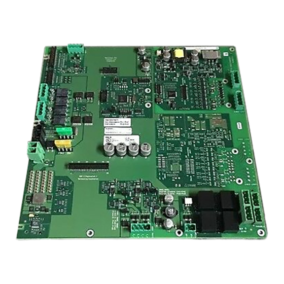
H1301 X602 X603 X601 S100 X605 X403 X604 X606 X902 X204 X901 F302 X1001 F301 X201 X202 X301 X302 X305 X303 X304 Figure 2: Printed circuit board view for FCI2016 8 | 46 Building Technologies A6V10315038_f_en_-- Siemens Industry, Inc. 2016-02-25... - Page 9 Output DC 24 V AUX X1101 Plug block for relay connections X1302 For future application X1401 Detector circuit circuit card 1, circuit 1 X1402 Detector circuit circuit card 1, circuit 2 9 | 46 A6V10315038_f_en_-- Building Technologies Siemens Industry, Inc. 2016-02-25...
-
Page 10: Configuration Input Power And Battery
A 2nd power supply (300 W) is only allowed in an housing (3HU). Jumper X305 must be plugged onto position 2-3. X302 BROO PSSI +26V Battery connection X303 BAT- BAT+ 10 | 46 Building Technologies A6V10315038_f_en_-- Siemens Industry, Inc. 2016-02-25... -
Page 11: X301 Power Supply Terminal Block 1
(Black) Return (ground) +24 V (Red) DC +24 V system supply Admissible cable cross-section: 1 x 12…18 AWG or 2 x 16…18 AWG 11 | 46 A6V10315038_f_en_-- Building Technologies Siemens Industry, Inc. 2016-02-25... -
Page 12: X302 Power Supply 2 Terminal Block
2 - 3 For a second power supply (300 W) in an housing (3HU). Activated PS 2 300 W The power supply is activated and is monitored by the system. 12 | 46 Building Technologies A6V10315038_f_en_-- Siemens Industry, Inc. 2016-02-25... -
Page 13: X304 Voice Supply +24 V
These circuits are for NAC circuits NFPA 72 Local only. For NFPA 72 Municipal Tie or NFPA 72 Leased Line, use the leased line/city tie module FCI2020. The module connects to X902. 13 | 46 A6V10315038_f_en_-- Building Technologies Siemens Industry, Inc. 2016-02-25... -
Page 14: Wiring The Nac Circuits
Positive feed for notification appliances for NAC 1 class A or NAC 1-2 class B NAC1-2 (-) Return feed for notification appliances for NAC 1 class A or NAC 1-2 class B Admissible cable cross-section: 1 x 12…18 AWG or 2 x 16…18 AWG 14 | 46 Building Technologies A6V10315038_f_en_-- Siemens Industry, Inc. 2016-02-25... -
Page 15: X602 Jumper - Enable/Disable Degraded Mode For Nac 1 Class A Or Nac 1-1 Class B
The class A/B configuration of the jumpers on the periphery board must be transferred in the Engineering tool set. An error is generated if the configurations do not match. 15 | 46 A6V10315038_f_en_-- Building Technologies Siemens Industry, Inc. 2016-02-25... -
Page 16: X403 Jumper - Degrade Alarm Silenceable
Input from external fire control panel and voice alarm fire control panel. The active positive output signal of the external fire control panel's NAC circuit connects here. Admissible cable cross-section: 1 x 12-18 AWG or 2 x 16-18 AWG 16 | 46 Building Technologies A6V10315038_f_en_-- Siemens Industry, Inc. 2016-02-25... -
Page 17: Auxiliary Dc 24 V Output
Programmable user relay The user programmable relay changes state depending on the configuration set in the Engineering tool set. In degrade mode, the user relay will not activate. 17 | 46 A6V10315038_f_en_-- Building Technologies Siemens Industry, Inc. 2016-02-25... -
Page 18: Wiring
(style 6) or four circuits (style 4). The detector circuits are isolated from the periphery board's main circuit. The circuit card has its own microprocessor for supervising ground fault, short-circuit, open circuit, and line capacity. 18 | 46 Building Technologies A6V10315038_f_en_-- Siemens Industry, Inc. 2016-02-25... -
Page 19: Wiring
Both circuits are supervised and power limited. No EOL required No EOL required Initiating device X1401 X1402 1+ 1- 1+ 1- Figure 6: Style 4 wiring Both circuits are supervised and power limited. 19 | 46 A6V10315038_f_en_-- Building Technologies Siemens Industry, Inc. 2016-02-25... -
Page 20: X1401 Terminal Block - Detector Circuit 1
1.11 Reset Buttons 1.11.1 S100 RESET periphery board Button Function Position Meaning S100 Not pressed Normal Reset main microprocessor on periphery board Pressed Resets only the main microprocessor on the periphery board. 20 | 46 Building Technologies A6V10315038_f_en_-- Siemens Industry, Inc. 2016-02-25... -
Page 21: Technical Data
DC 24 V nominal "Special Application" For use with: FN2006/FN2007, HZM, HCP, FCA2018, FT2014/FT2015, FTI2001 Curent Max. 1.5 A Design ● Short-circuit protection ● Voltage surge protection ● Power limited 21 | 46 A6V10315038_f_en_-- Building Technologies Siemens Industry, Inc. 2016-02-25... - Page 22 Alarm and trouble active in degraded mode operation Switching voltage DC 30 V or AC 120/240 V ohmic Switching current 5 A @ DC 30 V or AC 120 V 4 A @ AC 240 V 22 | 46 Building Technologies A6V10315038_f_en_-- Siemens Industry, Inc. 2016-02-25...
- Page 23 Admissible cable cross- section Voice alarm supply Connecting plug X304 Output +24 V Output voltage DC 24 V nominal, filtered Max. output current 20 A Design ● Not power limited ● Short-circuit-proof 23 | 46 A6V10315038_f_en_-- Building Technologies Siemens Industry, Inc. 2016-02-25...
- Page 24 Periphery board (250p) FCI2016 Technical data 24 | 46 Building Technologies A6V10315038_f_en_-- Siemens Industry, Inc. 2016-02-25...
-
Page 25: Periphery Board (500P) Fci2017
2 zones, and an additional NAC circuit (NAC 2). The periphery board has a battery charger and battery switchover circuit for AC fail or brownout. The battery charger is capable of charging up to 100 Ah batteries. 25 | 46 A6V10315038_f_en_-- Building Technologies Siemens Industry, Inc. 2016-02-25... - Page 26 X902. ● Additional peripheral data bus connection (X202) for LED or DACT modules. ● Main CPU and detector core CPUs capable of being updated in the field through the PMI. 26 | 46 Building Technologies A6V10315038_f_en_-- Siemens Industry, Inc. 2016-02-25...
-
Page 27: Installation
2. Wire the periphery board (500p) according to the pin assignments in the following chapters. 3. Set the jumpers. 4. Re-install any modules that you may have had to remove. 27 | 46 A6V10315038_f_en_-- Building Technologies Siemens Industry, Inc. 2016-02-25... -
Page 28: Views
Status indicator for detector core A (circuits 1 and 2) H1701 Status indicator for detector core B (circuits 3 and 4) Reset buttons S100 Reset button for microprocessor for periphery board circuitry (not including detector circuits) 28 | 46 Building Technologies A6V10315038_f_en_-- Siemens Industry, Inc. 2016-02-25... - Page 29 Detector circuit core A, circuit 1 X1402 Detector circuit core A, circuit 2 X1702 For future applications X1801 Detector circuit core B, circuit 3 X1802 Detector circuit core B, circuit 4 29 | 46 A6V10315038_f_en_-- Building Technologies Siemens Industry, Inc. 2016-02-25...
-
Page 30: Configuration Input Power And Battery
A 2nd power supply (300 W) is only allowed in an housing (3HU). Jumper X305 must be plugged onto position 2-3. X302 BROO PSSI +26V Battery connection X303 BAT- BAT+ 30 | 46 Building Technologies A6V10315038_f_en_-- Siemens Industry, Inc. 2016-02-25... -
Page 31: X301 Power Supply Terminal Block 1
(Black) Return (ground) +24 V (Red) DC +24 V system supply Admissible cable cross-section: 1 x 12…18 AWG or 2 x 16…18 AWG 31 | 46 A6V10315038_f_en_-- Building Technologies Siemens Industry, Inc. 2016-02-25... -
Page 32: X302 Power Supply 2 Terminal Block
VCA2002 Card Cage and for the connected peripherals. The cable that connects X304 on the Periphery Board to X101 on the Card Cage is included in the VCA2002's scope of supply. 32 | 46 Building Technologies A6V10315038_f_en_-- Siemens Industry, Inc. 2016-02-25... -
Page 33: X303 Battery Terminal
You will find information on the installation in the following documents: ● A6V10315015 for Desigo ● A6V10333409 for Cerberus PRO You will find information on the configuration in the following documents: ● A6V10315023 for Desigo ● A6V10333423 for Cerberus PRO 33 | 46 A6V10315038_f_en_-- Building Technologies Siemens Industry, Inc. 2016-02-25... -
Page 34: Wiring The Nac Circuits
Positive feed for notification appliances for NAC 1 class A or NAC 1-2 class B NAC1-2 (-) Return feed for notification appliances for NAC 1 class A or NAC 1-2 class B Admissible cable cross-section: 1 x 12…18 AWG or 2 x 16…18 AWG 34 | 46 Building Technologies A6V10315038_f_en_-- Siemens Industry, Inc. 2016-02-25... -
Page 35: Nac 1-2 Class B
The class A/B configuration of the jumpers on the periphery board must be transferred in the Engineering tool set. An error is generated if the configurations do not match. 35 | 46 A6V10315038_f_en_-- Building Technologies Siemens Industry, Inc. 2016-02-25... -
Page 36: X403 Jumper - Degrade Alarm Silenceable
Input from external fire control panel and voice alarm fire control panel. The active positive output signal of the external fire control panel's NAC circuit connects here. Admissible cable cross-section: 1 x 12-18 AWG or 2 x 16-18 AWG 36 | 46 Building Technologies A6V10315038_f_en_-- Siemens Industry, Inc. 2016-02-25... -
Page 37: Auxiliary Dc 24 V Output
Programmable user relay The user programmable relay changes state depending on the configuration set in the Engineering tool set. In degrade mode, the user relay will not activate. 37 | 46 A6V10315038_f_en_-- Building Technologies Siemens Industry, Inc. 2016-02-25... -
Page 38: Wiring
Each circuit driver can be configured for two style 6 circuits or four style 4 circuits: The detector circuits are isolated from the periphery board's main circuit. Each circuit card has a microprocessor which supervises ground fault, short-circuit, open circuit, and line capacity. 38 | 46 Building Technologies A6V10315038_f_en_-- Siemens Industry, Inc. 2016-02-25... -
Page 39: Wiring
Both circuits are supervised and power limited. No EOL required No EOL required Initiating device X1401 X1402 X1801 X1802 1+ 1- 1+ 1- Figure 12: Style 4 wiring Both circuits are supervised and power limited. 39 | 46 A6V10315038_f_en_-- Building Technologies Siemens Industry, Inc. 2016-02-25... -
Page 40: X1401 And X1801 Terminal Block - Detector Circuits 1 And 3
Positive output for circuit 2-2 or circuit 4-2 Return feed for circuit 2-1 or circuit 4-1 Positive output for circuit 2-1 or circuit 4-1 Admissible cable cross-section: 1 x 12…18 AWG or 2 x 16…18 AWG 40 | 46 Building Technologies A6V10315038_f_en_-- Siemens Industry, Inc. 2016-02-25... -
Page 41: Indicators
2.11 Reset Buttons 2.11.1 S100 RESET periphery board Button Function Position Meaning S100 Reset main microprocessor on Not pressed Normal periphery board Pressed Resets only the main microprocessor on the periphery board. 41 | 46 A6V10315038_f_en_-- Building Technologies Siemens Industry, Inc. 2016-02-25... -
Page 42: Technical Data
DC 24 V nominal "Special Application" For use with: FN2006/FN2007, HZM, HCP, FCA2018, FT2014/FT2015, FTI2001 Curent Max. 1.5 A Design ● Short-circuit protection ● Voltage surge protection ● Power limited 42 | 46 Building Technologies A6V10315038_f_en_-- Siemens Industry, Inc. 2016-02-25... - Page 43 Switching voltage DC 30 V or AC 120/240 V ohmic Switching current 5 A @ DC 30 V or AC 120 V 4 A @ AC 240 V 43 | 46 A6V10315038_f_en_-- Building Technologies Siemens Industry, Inc. 2016-02-25...
- Page 44 Once 12...18 AWG or twice 16...18 AWG Voice alarm supply Connecting plug X304 Output +24 V Output voltage DC 24 V nominal, filtered Max. output current 20 A Design ● Not power limited ● Short-circuit-proof 44 | 46 Building Technologies A6V10315038_f_en_-- Siemens Industry, Inc. 2016-02-25...
-
Page 45: Fcc Statement
Operation of this equipment in a residential area is likely to cause interference in which case the user at his own expense will be required to take whatever measures may be required to correct the interference. 45 | 46 A6V10315038_f_en_-- Building Technologies Siemens Industry, Inc. 2016-02-25... - Page 46 Issued by © Siemens Industry, Inc., 2011 Siemens Industry, Inc. Technical specifications and availability subject to change without notice. Building Technologies Division 8 Fernwood Road Florham Park, NJ 07932 +1 973-593-2600 www.sbt.siemens.com/FIS Document ID: A6V10315038_f_en_-- FS20/FS920 SAP order no.: A5Q00050751...