Table of Contents
Advertisement
Quick Links
Use
Siemens Building Technologies
Landis & Staefa Division
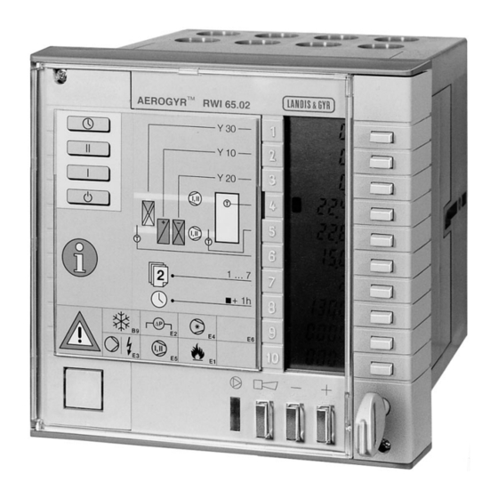
AEROGYR™
Controller
for central air handling
with single- or two-speed fans
Compact unit providing control and supervisory functions,
operating voltage AC 24 V, signal voltage DC 0...10 V.
In ventilating and air conditioning plants with
•
hot water heating coils or electric air heater batteries
•
direct expansion cooler batteries or chilled water cooling coils
•
recirculated air dampers or heat recovery (HR) equipment
The RWI65.02 is used to:
•
control
-
the room-supply air temperature or extract air-supply air temperature (cascade
control) with adjustable minimum and maximum limitations
-
the room-supply air temperature or extract air-supply air temperature (cascade
control) with room or extract air-dependent shifting minimum and maximum
limitations (displacement ventilation)
-
the supply air temperature
-
the CO
/ VOC content of the room air (demand controlled ventilation)
2
-
single- or two-speed fans
-
air coolers
-
chillers
-
HR equipment
-
hot water heating coils (with preheating)
-
electric air heater batteries (with fan overrun)
-
circulators in hot or chilled water circuits (load- or outside temperature-dependent)
-
air damper actuators (with recirculated startup circuit for modulating dampers)
-
regulating units in hot and chilled water circuits
3
204
RWI65.02
CM2N3204E / 1.1999
1/20
Advertisement
Table of Contents

Related Manuals for Siemens AEROGYR RWI65.02


Summary of Contents for Siemens AEROGYR RWI65.02
- Page 1 (load- or outside temperature-dependent) air damper actuators (with recirculated startup circuit for modulating dampers) regulating units in hot and chilled water circuits Siemens Building Technologies CM2N3204E / 1.1999 Landis & Staefa Division 1/20...
-
Page 2: Technical Design
For the control of mixed air dampers or HR equipment, both the operating action and the operating mode can be selected. The actual values of the various outputs are permanently displayed. CM2N3204E / 1.1999 Siemens Building Technologies 2/20 Landis & Staefa Division... - Page 3 «Z» • compensation across the entire setpoint range by a Landis & Staefa building auto- mation system via the FLN bus and FLN communication insert AZI65.1 Siemens Building Technologies CM2N3204E / 1.1999 Landis & Staefa Division 3/20...
- Page 4 I or II (depending on the preselected speed). Outputs Y10, Y20 and Y30 with operating action « \ » are disabled (0 %). The factory-set minimum operating time is 30 min. It is adjustable (from 0 min to 12 h). CM2N3204E / 1.1999 Siemens Building Technologies 4/20 Landis & Staefa Division...
- Page 5 Use of the following detectors is a prerequisite: QAE22... or QAD22 for frost protection on the water side. QAF63.2, QAF63.6 for frost protection on the air side. Siemens Building Technologies CM2N3204E / 1.1999 Landis & Staefa Division 5/20...
- Page 6 (off, speed I, or speed II) and a setpoint pair (Economy and Comfort); the settings are made on op- erating level 3. • Summer- / wintertime changeover CM2N3204E / 1.1999 Siemens Building Technologies 6/20 Landis & Staefa Division...
- Page 7 («A» or «b») Siemens Building Technologies CM2N3204E / 1.1999 Landis & Staefa Division...
- Page 8 For the effects of the fault status signals at the outputs of the RWI65.02, refer to the function flow diagrams on the last page of this data sheet. CM2N3204E / 1.1999 Siemens Building Technologies 8/20 Landis & Staefa Division...
-
Page 9: Mechanical Design
LED (green) for indication of the plant’s operational status (fans ON = LED lit, OFF = dark) Universal button with LED (red) for indication, acknowledgement and resetting of fault statuses Buttons for adjustments Key hole for opening the front door (key enclosed) Siemens Building Technologies CM2N3204E / 1.1999 Landis & Staefa Division 9/20... - Page 10 DIL switches Front door opened, cover removed AEROGYR RWI65.02 Test The controller is supplied with the DIL switches set to OFF. The switch positions have the following meaning: CM2N3204E / 1.1999 Siemens Building Technologies 10/20 Landis & Staefa Division...
-
Page 11: Engineering Notes
For commissioning, the Reference Manual, ordering no. CM2Z3204E, is required. notes When commissioning the plant, all functions of the controller and of the communication insert (if present) and the wiring of the connected units must be checked. Siemens Building Technologies CM2N3204E / 1.1999 Landis & Staefa Division 11/20... -
Page 12: Technical Data
Temperature < 85 % r.h. Humidity (non-condensing) Transport to IEC 721-3-2 Climatic conditions class 2K3 − 25...+ 70 °C Temperature < 95 % r.h. Humidity Mechanical conditions class 2M2 CM2N3204E / 1.1999 Siemens Building Technologies 12/20 Landis & Staefa Division... -
Page 13: Connection Diagram
UP, UN Connections (2...3) for communication LG-Ni1000 Ω detectors = L & S standard Note: Control signal outputs Y20 and Q13 / Q24 are available at the same time Siemens Building Technologies CM2N3204E / 1.1999 Landis & Staefa Division 13/20... -
Page 14: Wiring Diagrams
G G0 Wiring diagram 4: measuring part with passive remote setting unit Wiring diagram 5: measuring part with extract air temperature detector for limit control (anti-icing protection with HR) CM2N3204E / 1.1999 Siemens Building Technologies 14/20 Landis & Staefa Division... - Page 15 Motor contactor for hot water pump or contactor for electric heater battery Motor contactor for chilled water circulator or chiller Motor contactor for fan speed I Motor contactor for fan speed II Siemens Building Technologies CM2N3204E / 1.1999 Landis & Staefa Division 15/20...
- Page 16 E3 Overload pump/electric A / b E4 Overload chiller A / b E5 Overload fan A / b E6 AUX, freely available A / b B9 Frost alarm A / b CM2N3204E / 1.1999 Siemens Building Technologies 16/20 Landis & Staefa Division...
- Page 17 To protect the plant, the second fan speed is disabled at very low outside temperatures. In that case, only the first fan speed will be enabled. To avoid unnecessary fan speed changes when outside temperatures greatly vary, a hysteresis of 2 K is used Siemens Building Technologies CM2N3204E / 1.1999 Landis & Staefa Division...
- Page 18 Electr. Electr. Water Risk of frost Water Off if Y10 ≥ 0 % Dark On if Y10 ≥ 0 % Off (delayed) Flashing Dark if Y10 ≥ 0 % CM2N3204E / 1.1999 Siemens Building Technologies 18/20 Landis & Staefa Division...
- Page 19 Water Electr. Electr. Water Risk of frost Water Off if Y10 ≥ 0 % Dark On if Y10 ≥ 0 % Flashing Off(delayed) Dark if (Y10 ≥ 0 %) Siemens Building Technologies CM2N3204E / 1.1999 Landis & Staefa Division 19/20...
- Page 20 Dimensions 272,5 13,5 152,6 Pg 11 17,5 106,5 24 30,3 © 1999 Siemens Building Technologies Ltd. Dimensions in mm CM2N3204E / 1.1999 Siemens Building Technologies 20/20 Landis & Staefa Division...