Table of Contents
Advertisement
SITOP power supply
SITOP PSU6200 1ph
Manual
SITOP PSU6200 12 V/7 A
6EP3323-7SB00-0AX0
SITOP PSU6200 12 V/12 A
6EP3324-7SB00-3AX0
SITOP PSU6200 24 V/3.7 A
6EP3333-7LB00-0AX0
SITOP PSU6200 24 V/5 A
6EP3333-7SB00-0AX0
SITOP PSU6200 24 V/10 A
6EP3334-7SB00-3AX0
SITOP PSU6200 24 V/20 A
6EP3336-7SB00-3AX0
03.2019
A5E44623264-1-76
___________________
Overview
___________________
Notes on safety
___________________
Description, device design,
dimension drawing
___________________
Mounting/removal
___________________
Mounting position, mounting
clearances
___________________
Installation
___________________
Technical data
___________________
Safety, approvals, EMC
___________________
Ambient conditions
___________________
Applications
___________________
Environment
___________________
Service & Support
1
2
3
4
5
6
7
8
9
10
11
Advertisement
Table of Contents

Related Manuals for Siemens SITOP PSU6200


Summary of Contents for Siemens SITOP PSU6200
- Page 1 ___________________ Ambient conditions ___________________ Applications ___________________ Environment ___________________ Service & Support SITOP PSU6200 12 V/7 A 6EP3323-7SB00-0AX0 SITOP PSU6200 12 V/12 A 6EP3324-7SB00-3AX0 SITOP PSU6200 24 V/3.7 A 6EP3333-7LB00-0AX0 SITOP PSU6200 24 V/5 A 6EP3333-7SB00-0AX0 SITOP PSU6200 24 V/10 A...
- Page 2 Note the following: WARNING Siemens products may only be used for the applications described in the catalog and in the relevant technical documentation. If products and components from other manufacturers are used, these must be recommended or approved by Siemens. Proper transport, storage, installation, assembly, commissioning, operation and maintenance are required to ensure that the products operate safely and without any problems.
-
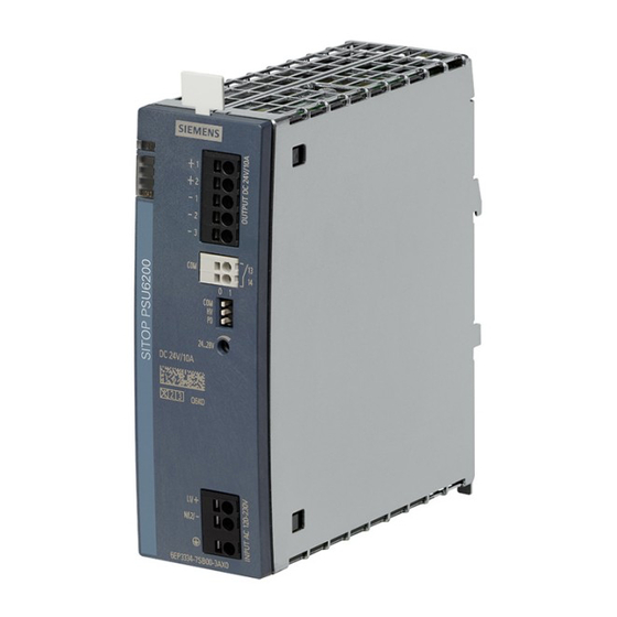
Page 3: Overview
Figure 1 View of devices The 1-phase SITOP PSU6200 from the product line is a powerful, regulated standard power supply for automated machines and systems. In addition to a high efficiency, these low- profile power supply units have an outstanding overload behavior. - Page 4 120 - 240 V DC 24 V/10 A DC output Input 1 AC 120/230 V, 6EP3336-7SB00-3AX0 120 - 240 V DC 24 V/20 A DC output Accessories Type Order number Reference labeling plate (160 plates) 6ES7193-6LF30-0AW0 SITOP PSU6200 1ph Manual, 03.2019, A5E44623264-1-76...
-
Page 5: Table Of Contents
Output-side connection ......................41 Technical data ............................43 Input ............................43 Output ............................. 46 Efficiency ..........................52 Closed-loop control ......................... 56 Protection and monitoring ....................... 57 MTBF ............................58 Mechanical system ......................... 59 Dimension drawing ......................... 60 SITOP PSU6200 1ph Manual, 03.2019, A5E44623264-1-76... - Page 6 Parallel connection to increase the power rating ..............67 Overload protection in the 24 V output circuit ................ 69 Protection against short-time voltage dips ................70 Protecting against longer power failures ................71 Environment ............................73 Service & Support ............................ 75 SITOP PSU6200 1ph Manual, 03.2019, A5E44623264-1-76...
-
Page 7: Notes On Safety
Before installation or maintenance work can begin, the system's main switch must be switched off and measures taken to prevent it being switched on again. If this instruction is not observed, touching live parts can result in death or serious injury. SITOP PSU6200 1ph Manual, 03.2019, A5E44623264-1-76... - Page 8 Notes on safety SITOP PSU6200 1ph Manual, 03.2019, A5E44623264-1-76...
-
Page 9: Description, Device Design, Dimension Drawing
Description, device design, dimension drawing Device description SITOP PSU6200 is a primary-clocked power supply for connection to a 1-phase AC line supply and a DC supply. An electronically regulated DC voltage that can be set via a potentiometer is available at the output of the device. The output of the device is isolated, no-load proof and short-circuit proof. -
Page 10: Connections And Terminal Designation
Do not subject the end stop to higher loads Figure 2-2 Terminal data for 6EP3323-7SB00-0AX0, 6EP3324-7SB00-3AX0, 6EP3333-7LB00- 0AX0, 6EP3333-7SB00-0AX0 and 6EP3334-7SB00-3AX0 Do not subject the end stop to higher loads Figure 2-3 Terminal data for 6EP3336-7SB00-3AX0 SITOP PSU6200 1ph Manual, 03.2019, A5E44623264-1-76... -
Page 11: Potentiometer
3 °C/V. Note It is only permissible to use an insulated screwdriver when actuating the potentiometer. For information on actuating the potentiometer (screwdriver, torque), see Connections and terminal designation (Page 10). SITOP PSU6200 1ph Manual, 03.2019, A5E44623264-1-76... -
Page 12: Status Displays And Signaling
24 V AC/0.1 A; 30 V DC/0.1 A closed: NOTICE: It is not permissible that the signal- NOTICE: It is not permissible that the signal- ing contact is connected on the primary side! ing contact is connected on the primary side! SITOP PSU6200 1ph Manual, 03.2019, A5E44623264-1-76... - Page 13 (for DIP switch COM = 0) NOTICE: It is not permissible that the con- NOTICE: It is not permissible that the con- tact is connected on the primary side! tact is connected on the primary side! Diagnostic monitor display: SITOP PSU6200 1ph Manual, 03.2019, A5E44623264-1-76...
- Page 14 Description, device design, dimension drawing 2.4 Status displays and signaling Service life < 10 % SITOP PSU6200 1ph Manual, 03.2019, A5E44623264-1-76...
-
Page 15: Operating Mode
Switching over output characteristic 0: Constant output voltage "single operation" 1: Load-de- pendent output voltage "parallel operation" Additional information can be found in the documents: ● Diagnostics interface (https://support.industry.siemens.com/cs/ww/en/view/109763467) ● Faceplates and communication blocks (https://support.industry.siemens.com/cs/ww/en/view/109760217) SITOP PSU6200 1ph Manual, 03.2019, A5E44623264-1-76... -
Page 16: Block Diagram
Description, device design, dimension drawing 2.6 Block diagram Block diagram Figure 2-7 Block diagram 3.7/5/7 A SITOP PSU6200 1ph Manual, 03.2019, A5E44623264-1-76... - Page 17 Description, device design, dimension drawing 2.6 Block diagram Figure 2-8 Block diagram 10/12/20 A SITOP PSU6200 1ph Manual, 03.2019, A5E44623264-1-76...
-
Page 18: Dimensions And Weight
Description, device design, dimension drawing 2.7 Dimensions and weight Dimensions and weight Figure 2-9 Dimension drawing 6EP3323-7SB00-0AX0 6EP3333-7LB00-0AX0 6EP3333-7SB00-0AX0 SITOP PSU6200 1ph Manual, 03.2019, A5E44623264-1-76... - Page 19 Description, device design, dimension drawing 2.7 Dimensions and weight Figure 2-10 Dimension drawing 6EP3324-7SB00-3AX0 6EP3334-7SB00-3AX0 Figure 2-11 Dimension drawing 6EP3336-7SB00-3AX0 SITOP PSU6200 1ph Manual, 03.2019, A5E44623264-1-76...
- Page 20 (24 V/5 A) Dimensions 35 × 135 × 125 45 × 135 × 125 70 × 135 × 155 (W × H × D) in mm Weight Approx. 0.7 kg Approx. 0.9 kg Approx. 1.5 kg SITOP PSU6200 1ph Manual, 03.2019, A5E44623264-1-76...
-
Page 21: Mounting/Removal
WARNING Installing the device in a housing or a control cabinet SITOP PSU6200 power supplies are built-in devices. They must be installed in a housing or control cabinet where only qualified personnel have access. The device can be mounted in a control cabinet on standard mounting rails according to TH35-15/7,5 (EN 60715). - Page 22 Mounting/removal SITOP PSU6200 1ph Manual, 03.2019, A5E44623264-1-76...
-
Page 23: Mounting Position, Mounting Clearances
Lateral clearances do not have to be maintained. Output current as a function of the ambient temperature and mounting height Figure 4-1 6EP3323-7SB00-0AX0 output current in the standard mounting position Figure 4-2 6EP3324-7SB00-3AX0 output current in the standard mounting position SITOP PSU6200 1ph Manual, 03.2019, A5E44623264-1-76... - Page 24 4.1 Standard mounting position Figure 4-3 6EP3333-7LB00-0AX0 output current in the standard mounting position Figure 4-4 6EP3333-7SB00-0AX0 output current in the standard mounting position Figure 4-5 6EP3334-7SB00-3AX0 output current in the standard mounting position SITOP PSU6200 1ph Manual, 03.2019, A5E44623264-1-76...
- Page 25 Mounting position, mounting clearances 4.1 Standard mounting position Figure 4-6 6EP3336-7SB00-3AX0 output current in the standard mounting position Figure 4-7 Mounting height derating Details see chapter Ambient conditions (Page 65) SITOP PSU6200 1ph Manual, 03.2019, A5E44623264-1-76...
-
Page 26: Other Mounting Positions
Particularly when installing on a vertically fastened standard mounting rail, additional measures may be required, e.g. to prevent the device from slipping on the standard mounting rail. 4.2.1 6EP3323-7SB00-0AX0 Figure 4-8 6EP3323-7SB00-0AX0 mounting position 1 Figure 4-9 6EP3323-7SB00-0AX0 mounting position 2 SITOP PSU6200 1ph Manual, 03.2019, A5E44623264-1-76... - Page 27 Mounting position, mounting clearances 4.2 Other mounting positions Figure 4-10 6EP3323-7SB00-0AX0 mounting position 3 Figure 4-11 6EP3323-7SB00-0AX0 mounting position 4 Figure 4-12 6EP3323-7SB00-0AX0 mounting position 5 SITOP PSU6200 1ph Manual, 03.2019, A5E44623264-1-76...
-
Page 28: 6Ep3324-7Sb00-3Ax0
Mounting position, mounting clearances 4.2 Other mounting positions 4.2.2 6EP3324-7SB00-3AX0 Figure 4-13 6EP3324-7SB00-3AX0 mounting position 1 Figure 4-14 6EP3324-7SB00-3AX0 mounting position 2 Figure 4-15 6EP3324-7SB00-3AX0 mounting position 3 SITOP PSU6200 1ph Manual, 03.2019, A5E44623264-1-76... - Page 29 Mounting position, mounting clearances 4.2 Other mounting positions Figure 4-16 6EP3324-7SB00-3AX0 mounting position 4 Figure 4-17 6EP3324-7SB00-3AX0 mounting position 5 SITOP PSU6200 1ph Manual, 03.2019, A5E44623264-1-76...
-
Page 30: 6Ep3333-7Lb00-0Ax0
Mounting position, mounting clearances 4.2 Other mounting positions 4.2.3 6EP3333-7LB00-0AX0 Figure 4-18 6EP3333-7LB00-0AX0 mounting position 1 Figure 4-19 6EP3333-7LB00-0AX0 mounting position 2 Figure 4-20 6EP3333-7LB00-0AX0 mounting position 3 SITOP PSU6200 1ph Manual, 03.2019, A5E44623264-1-76... - Page 31 Mounting position, mounting clearances 4.2 Other mounting positions Figure 4-21 6EP3333-7LB00-0AX0 mounting position 4 Figure 4-22 6EP3333-7LB00-0AX0 mounting position 5 SITOP PSU6200 1ph Manual, 03.2019, A5E44623264-1-76...
-
Page 32: 6Ep3333-7Sb00-0Ax0
Mounting position, mounting clearances 4.2 Other mounting positions 4.2.4 6EP3333-7SB00-0AX0 Figure 4-23 6EP3333-7SB00-0AX0 mounting position 1 Figure 4-24 6EP3333-7SB00-0AX0 mounting position 2 Figure 4-25 6EP3333-7SB00-0AX0 mounting position 3 SITOP PSU6200 1ph Manual, 03.2019, A5E44623264-1-76... - Page 33 Mounting position, mounting clearances 4.2 Other mounting positions Figure 4-26 6EP3333-7SB00-0AX0 mounting position 4 Figure 4-27 6EP3333-7SB00-0AX0 mounting position 5 SITOP PSU6200 1ph Manual, 03.2019, A5E44623264-1-76...
-
Page 34: 6Ep3334-7Sb00-3Ax0
Mounting position, mounting clearances 4.2 Other mounting positions 4.2.5 6EP3334-7SB00-3AX0 Figure 4-28 6EP3334-7SB00-3AX0 mounting position 1 Figure 4-29 6EP3334-7SB00-3AX0 mounting position 2 Figure 4-30 6EP3334-7SB00-3AX0 mounting position 3 SITOP PSU6200 1ph Manual, 03.2019, A5E44623264-1-76... - Page 35 Mounting position, mounting clearances 4.2 Other mounting positions Figure 4-31 6EP3334-7SB00-3AX0 mounting position 4 Figure 4-32 6EP3334-7SB00-3AX0 mounting position 5 SITOP PSU6200 1ph Manual, 03.2019, A5E44623264-1-76...
-
Page 36: 6Ep3336-7Sb00-3Ax0
Mounting position, mounting clearances 4.2 Other mounting positions 4.2.6 6EP3336-7SB00-3AX0 Figure 4-33 6EP3336-7SB00-3AX0 mounting position 1 Figure 4-34 6EP3336-7SB00-3AX0 mounting position 2 Figure 4-35 6EP3336-7SB00-3AX0 mounting position 3 SITOP PSU6200 1ph Manual, 03.2019, A5E44623264-1-76... - Page 37 Mounting position, mounting clearances 4.2 Other mounting positions Figure 4-36 6EP3336-7SB00-3AX0 mounting position 4 Figure 4-37 6EP3336-7SB00-3AX0 mounting position 5 SITOP PSU6200 1ph Manual, 03.2019, A5E44623264-1-76...
- Page 38 Mounting position, mounting clearances 4.2 Other mounting positions SITOP PSU6200 1ph Manual, 03.2019, A5E44623264-1-76...
-
Page 39: Installation
Line-side connection SITOP PSU6200 power supplies are designed for connection to a 1-phase AC line supply (TN-, TT or IT line supply according to IEC 60364-1 with rated voltage 120 - 230 V AC, 50 - 60 Hz or a DC power supply with 120 V - 240 V DC (3.7 A/24 V, 5 A/24 V, 7 A/12 V) or... - Page 40 Other country-specific regulations may have to be observed when installing the device. Note For operation on a DC power system (DC), the plus pole (+) must be connected to L1 and the minus pole (–) to N. SITOP PSU6200 1ph Manual, 03.2019, A5E44623264-1-76...
-
Page 41: Output-Side Connection
5.2 Output-side connection Output-side connection SITOP PSU6200 power supplies provide at their outputs an isolated (= non-grounded) SELV output voltage (Safety Extra Low Voltage). The output of the power supply is no-load, overload, and short-circuit proof. If an overload occurs, the electronic current limitation limits the output current to a maximum value (refer to chapter Technical data (Page 43)). - Page 42 Installation 5.2 Output-side connection SITOP PSU6200 1ph Manual, 03.2019, A5E44623264-1-76...
-
Page 43: Technical Data
Recommended: Miniature circuit Recommended: Circuit breaker, C (IEC 898) breaker characteristic C, 6 A characteristic, 6 A Power consumption (active power) at 100 W 97 W full load Overvoltage strength 300 V AC for 30 seconds SITOP PSU6200 1ph Manual, 03.2019, A5E44623264-1-76... - Page 44 6 A characteristic C, 10 A characteristic C, 10 A Power consumption 100 W 133 W 260 W 500 W (active power) at full load Overvoltage strength 300 V AC for 30 seconds SITOP PSU6200 1ph Manual, 03.2019, A5E44623264-1-76...
- Page 45 Technical data 6.1 Input Figure 6-1 Power-failure buffering SITOP PSU6200 1ph Manual, 03.2019, A5E44623264-1-76...
-
Page 46: Output
Output characteristic see Figure 6-3 Output characteristic see Figure 6-4 Output characteristic 6EP3323-7SB00-0AX0 single operation 6EP3324-7SB00-3AX0 single operation (Page 48) (Page 49) Capacitive load, max. 2 mF/A SITOP PSU6200 1ph Manual, 03.2019, A5E44623264-1-76... - Page 47 Active power output, 89 W 120 W 240 W 480 W typ. Overload capability 7.5 A for 5 s/min 15 A for 5 s/min 30 A for 5 s/min (Extra Power) SITOP PSU6200 1ph Manual, 03.2019, A5E44623264-1-76...
- Page 48 6EP3336-7SB00-3AX0 single operation single operation single operation single operation (Page 49) (Page 49) (Page 50) (Page 50) Capacitive load, max. 2 mF/A Figure 6-2 Startup delay/voltage rise Figure 6-3 Output characteristic 6EP3323-7SB00-0AX0 single operation SITOP PSU6200 1ph Manual, 03.2019, A5E44623264-1-76...
- Page 49 Technical data 6.2 Output Figure 6-4 Output characteristic 6EP3324-7SB00-3AX0 single operation Figure 6-5 Output characteristic 6EP3333-7LB00-0AX0 single operation Figure 6-6 Output characteristic 6EP3333-7SB00-0AX0 single operation SITOP PSU6200 1ph Manual, 03.2019, A5E44623264-1-76...
- Page 50 When the output voltage falls below approx. 10 V, the 6EP1336-2BA10 device switches off, and automatically restarts. This response is repeated as long as the overload condition is present. SITOP PSU6200 1ph Manual, 03.2019, A5E44623264-1-76...
- Page 51 Selector switch A on (parallel operation): The output voltage falls with increasing output current. Figure 6-9 Output characteristic 6EP3324-7SB00-3AX0 parallel operation Figure 6-10 Output characteristic 6EP3334-7SB00-3AX0 parallel operation Figure 6-11 Output characteristic 6EP3336-7SB00-3AX0 parallel operation SITOP PSU6200 1ph Manual, 03.2019, A5E44623264-1-76...
-
Page 52: Efficiency
Power loss when idling 1.5 W / 2.3 W 1.3 W / 2 W 2.6 W / 2.2 W 2.5 W / 2.5 W 120 V / 230 V AC approx. Figure 6-12 Efficiency 6EP3323-7SB00-0AX0 SITOP PSU6200 1ph Manual, 03.2019, A5E44623264-1-76... - Page 53 Technical data 6.3 Efficiency Figure 6-13 Efficiency 6EP3324-7SB00-3AX Figure 6-14 Efficiency 6EP3333-7LB00-0AX0 SITOP PSU6200 1ph Manual, 03.2019, A5E44623264-1-76...
- Page 54 Technical data 6.3 Efficiency Figure 6-15 Efficiency 6EP3333-7SB00-0AX0 Figure 6-16 Efficiency 6EP3334-7SB00-3AX0 SITOP PSU6200 1ph Manual, 03.2019, A5E44623264-1-76...
- Page 55 Technical data 6.3 Efficiency Figure 6-17 Efficiency 6EP3336-7SB00-3AX0 SITOP PSU6200 1ph Manual, 03.2019, A5E44623264-1-76...
-
Page 56: Closed-Loop Control
0.5 ms 10 to 90 %, typ. Load-step settling time 1 ms 1 ms 1 ms 90 to 10 %, max. Load-step settling time 0.5 ms 0.5 ms 0.5 ms 90 to 10 %, typ. SITOP PSU6200 1ph Manual, 03.2019, A5E44623264-1-76... -
Page 57: Protection And Monitoring
5 s/min 5 s/min 5 s/min Short-circuit protection electronic trip, automatic restart (hiccup) Overload / short-circuit Diagnostics monitor, see Chapter Status dis- display plays and signaling (Page 12) SITOP PSU6200 1ph Manual, 03.2019, A5E44623264-1-76... -
Page 58: Mtbf
6EP3324-7SB00-3AX0 (12 V/12 A) 6EP3333-7LB00-0AX0 (24 V/3,7 A) 6EP3333-7SB00-0AX0 (24 V/5 A) 6EP3334-7SB00-3AX0 (24 V/10 A) 6EP3336-7SB00-3AX0 (24 V/20 A) Mean Time Between Failures SN29500:> 500000 h at 40 °C, rated load, 24 h operation SITOP PSU6200 1ph Manual, 03.2019, A5E44623264-1-76... -
Page 59: Mechanical System
Type of mounting: Wall/panel mounting Type of mounting: Rail mounting Type of mounting: S7-300 rail mounting Mounting Can be snapped onto standard TH35-15/7,5 (EN 60715) mounting rails SITOP PSU6200 1ph Manual, 03.2019, A5E44623264-1-76... -
Page 60: Dimension Drawing
Technical data 6.8 Dimension drawing Dimension drawing See chapter Dimensions and weight (Page 18) CAD data that can be downloaded from the Internet: 6EP3323-7SB00-0AX0 (http://www.automation.siemens.com/bilddb/index.aspx?objKey=G_KT01_XX_01489) 6EP3324-7SB00-3AX0 (http://www.automation.siemens.com/bilddb/index.aspx?objKey=G_KT01_XX_01492) 6EP3333-7LB00-0AX0 (http://www.automation.siemens.com/bilddb/index.aspx?objKey=G_KT01_XX_01501) 6EP3333-7SB00-0AX0 (http://www.automation.siemens.com/bilddb/index.aspx?objKey=G_KT01_XX_01504) 6EP3334-7SB00-3AX0 (http://www.automation.siemens.com/bilddb/index.aspx?objKey=G_KT01_XX_01507) 6EP3336-7SB00-3AX0 (http://www.automation.siemens.com/bilddb/index.aspx?objKey=G_KT01_XX_01510) SITOP PSU6200 1ph Manual, 03.2019, A5E44623264-1-76... -
Page 61: Safety, Approvals, Emc
Transformer according to EN 61558-2-16 Protection class Class I Degree of protection (EN 60529) IP20 Leakage current, typ. 1 mA Leakage current, max. 3.5 mA Test voltage See Table 7-1 Test voltage (Page 62) SITOP PSU6200 1ph Manual, 03.2019, A5E44623264-1-76... -
Page 62: Test Voltage
850 V DC Production test 4200 V DC 2200 V DC 850 V DC Field test 4200 V DC 2200 V DC 850 V DC Remark: Tripping current for DC measurement: max. 10 mA SITOP PSU6200 1ph Manual, 03.2019, A5E44623264-1-76... -
Page 63: Approvals
Yes, CSA C22.2 No. 60950-1, cCSAus (ANSI/ISA 12.12.01) UL/cUL approval cULus-listed (UL 508, CSA 22.2 No. 107.1), File E197259, for 6EP3333-7LB00-0AX0: NEC class2 (acc. to UL 60950-1/UL 1310), File E151273 CB approval CB-Scheme IEC 60950-1 SEMI F47 Marine approvals Available soon SITOP PSU6200 1ph Manual, 03.2019, A5E44623264-1-76... -
Page 64: Emc
Voltage interruptions EN 61000-4-11 100% for 5000 ms Emitted interference EN 55022 Class B Line harmonics limitation EN 61000-3-2 Class A Generic standards EN 61000-6-2 Immunity for industrial environments EN 61000-6-3 Emission for residential areas SITOP PSU6200 1ph Manual, 03.2019, A5E44623264-1-76... -
Page 65: Ambient Conditions
3.5 mm deflection in the range 5 – 8.4 Hz 2 g acceleration in the range 8.4 – 150 Hz EN 60068-2-27 shock, test Ea: • acceleration 150 m/s , test duration 11 ms SITOP PSU6200 1ph Manual, 03.2019, A5E44623264-1-76... - Page 66 II from 2000 m to 6000 m (EN 50178) II to 2000 m (EN 60950-1) I from 2000 m to 6000 m (EN 60950-1) Storage: 1080 - 660 hPa (0 - 3500 m) • SITOP PSU6200 1ph Manual, 03.2019, A5E44623264-1-76...
-
Page 67: Applications
Figure 9-1 Parallel connection Note It is not permissible to take into account simultaneous overload capability (Extra-Power 150% for 5 s/min) of several power supplies connected in parallel when configuring the power supply system. SITOP PSU6200 1ph Manual, 03.2019, A5E44623264-1-76... - Page 68 For this purpose, a suitable protective circuit (e.g. decoupling diode or DC-capable circuit breaker) must be installed between each "+" terminal of the power supply and the common connection point. SITOP PSU6200 1ph Manual, 03.2019, A5E44623264-1-76...
-
Page 69: Overload Protection In The 24 V Output Circuit
SIMATIC S7-1200/1500/300/400, for STEP 7 Classic and TIA Portal at no charge. You can find additional information at: Manual SITOP selectivity modules (https://support.industry.siemens.com/cs/ww/en/view/108989004) Figure 9-2 Electronic protection of 24 V loads using the SITOP PSE200U selectivity module SITOP PSU6200 1ph Manual, 03.2019, A5E44623264-1-76... -
Page 70: Protection Against Short-Time Voltage Dips
5 A. This time can be increased a multiple number of times by connecting buffer modules in parallel; the maximum buffer time is 10 s. You can find additional information at: SITOP PSE201U manual (https://support.industry.siemens.com/cs/ww/en/view/41129219) Figure 9-3 Buffering brief power failures using the SITOP PSE201U buffer module SITOP PSU6200 1ph Manual, 03.2019, A5E44623264-1-76... -
Page 71: Protecting Against Longer Power Failures
Using the free-of-charge SITOP DC-UPS software tool, DC-UPS systems can be simply integrated into PC-based automation solutions. This supports further processing of the status signals and safely running down the PC. You can find additional information at: Manual, DC UPS with capacitors (https://support.industry.siemens.com/cs/ww/en/ps/18042/man) SITOP PSU6200 1ph Manual, 03.2019, A5E44623264-1-76... - Page 72 – make it easy to integrate operating and diagnostics information into STEP 7 user programs. Preconfigured UPS faceplates for WinCC visualization can be downloaded at no charge. You can find additional information at: DC UPS SITOP UPS1600/UPS1100 Manual (https://support.industry.siemens.com/cs/ww/en/view/84977415) SITOP PSU6200 1ph Manual, 03.2019, A5E44623264-1-76...
-
Page 73: Environment
The devices are in conformance with RoHS. As a rule, only non-silicon precipitating materials are used. Disposal guidelines Packaging and packaging aids can and should always be recycled. The product itself may not be disposed of as domestic refuse. SITOP PSU6200 1ph Manual, 03.2019, A5E44623264-1-76... - Page 74 Environment SITOP PSU6200 1ph Manual, 03.2019, A5E44623264-1-76...
-
Page 75: Service & Support
Technical support for all IA/DT products can be accessed through the following communication channels: ● Telephone: + 49 (0) 911 895 7222 ● Internet: Web form for support request (http://www.siemens.de/automation/support-request) Technical documentation on the Internet Operating instructions and manuals for SITOP are available in the Internet: Operating instructions/manuals (http://www.siemens.com/sitop/manuals) - Page 76 Service & Support Contact persons If you have any questions regarding the use of our products, then contact the Siemens contact person in your regional Siemens sales office. You can find these addresses as follows: ● On the Internet (http://www.automation.siemens.com/partner) ●...