ABB UZE Repair Manual
On-load tap-changers with motor-drive mechanism
Hide thumbs
Also See for UZE:
- Installation and commissioning manual (24 pages) ,
- Installation and commissioning manual (44 pages)

Related Manuals for ABB UZE


Summary of Contents for ABB UZE
- Page 1 1ZSE 5492-128 en, Rev. 4 On-load tap-changers, type UZE and UZF, with motor-drive mechanism, type BUF 3 Repair guide...
- Page 2 This document must not be copied without our written permission, and the contents thereof must not be imparted to a third party nor be used for any unauthorized purpose. Contravention will be prosecuted.
- Page 3 Recommended practices ABB recommends careful consideration of the following factors for service and repair work on on-load tap-changers. Do not repair an on-load tap-changer or motor-drive mechanism with a serious mechani- cal or electrical fault without first consulting ABB. Before you start any work, make sure that the personnel doing the job have read and fully understood the Repair documents provided with the unit.
- Page 4 During service WARNING Small amounts of explosive gases will always come out from the breathing devices (dehydrating breather or one-way breather). Make sure that no open fire, hot surfaces or sparks occur in the immediate surroundings of the breathing devices. If a failure in power supply occurs during operation, the operation will be completed when the power returns.
- Page 5 CAUTION Take care to avoid ingestion of moist air when oil is drained. If the ambient air is moist, let incoming air pass through a dehydrating breather with slow air flow to obtain proper dehy- dration. Do not fill oil into the on-load tap-changer if the transformer tank is under vacuum and the on-load tap-changer is not.
-
Page 7: Table Of Contents
Contents 1. Introduction _______________________________________________________9 1.1 General _______________________________________________________9 1.2 Repair categories _______________________________________________9 1.3 Serial number __________________________________________________9 1.4 Spare parts list _________________________________________________10 1.5 Maintenance guide ______________________________________________11 1.6 Tightening torque _______________________________________________11 2. Trouble-shooting ___________________________________________________12 2.1 On-load tap-changer ____________________________________________12 2.2 Pressure relay __________________________________________________12 2 Trouble-shooting _____________________________________________13 2.3 Motor-drive mechanism __________________________________________14 2.3.1 Control system _____________________________________________14... -
Page 9: Introduction
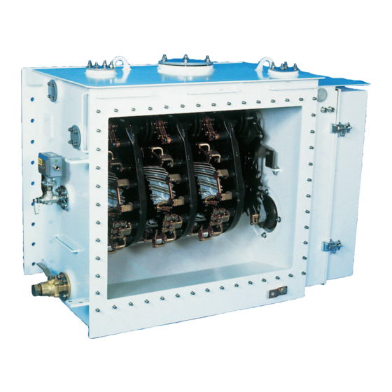
The design allows excellent access to all parts, making inspection and maintenance quick and simple. The on-load tap-changer type UZE/UZF is placed in a oil filled tank separated from the transformer tank. The motor-drive mechanism is attached to the side of the on-load tap- changer tank. -
Page 10: Spare Parts List
For information about spare parts, please see the Spare Parts List 1ZSE 5492-132, On- Load Tap-Changers, types UZE and UZF with Motor-Drive Mechanism, type BUF 3. The Spare Parts List also contains several exploded views, which can be very handy when making repairs. -
Page 11: Maintenance Guide
1 Introduction Rating plate fm_00102 Fig. 2. Location of rating plate. 1.5 Maintenance guide Inspection and overhaul of the UZ-type on-load tap-changer is carried out according to the instructions in the Maintenance Guide. Contact replacement is also described in the Main- tenance Guide. -
Page 12: Trouble-Shooting
2 Trouble-shooting 2. Trouble-shooting This chapter mainly contains infomation used to locate a fault. Instructions for correcting the fault, replacement of parts etc. are contained in chapter 3, Repairs and Adjustments. 2.1 On-load tap-changer Error condition Fault finding procedure High oil level alarm. A rising oil level in the on-load tap-changer oil conserva- tor may indicate a leakage between the on-load tap- changer and the transformer main tank. -
Page 13: Trouble-Shooting
2 Trouble-shooting Error condition Fault finding procedure 1. After a pressure relay trip, the on-load tap-changer and the transformer must be carefully investigated. That means that the on-load tap-changer must be drained and the front cover opened. Faults, if any, must be repaired before the transformer is energized. -
Page 14: Motor-Drive Mechanism
2 Trouble-shooting Information plate Valve handle Connection nut Test tap (R 1/8’’) fm_00117 Fig. 5. Pressure relay. 2.3 Motor-drive mechanism 2.3.1 Control system Error condition Fault finding procedure LOCAL operation or REMOTE LOCAL operation is not possible when the control selec- operation is not possible. - Page 15 2 Trouble-shooting Error condition Fault finding procedure The on-load tap-changer 1. If the on-load tap-changer makes more than three performs more steps than operations there must be a failure in the time relay for ordered, or operates towards the running through protection. the end stop.
-
Page 16: Power System
Water in the motor-drive 1. Adjust the hinges on the cabinet door. mechanism cabinet. 2. Replace the door gasket on the cabinet. Oil in the motor-drive mecha- 1. Locate the leakage. nism cabinet. 2. Contact ABB. 1ZSE 5492-128 en, Rev. 4... - Page 17 2 Trouble-shooting fm_00120 Fig. 3. Circuit diagram 1ZSE 5492-128 en, Rev. 4...
- Page 18 2 Trouble-shooting fm_00113 Fig. 4. Contact timing diagram 1ZSE 5492-128 en, Rev. 4...
-
Page 19: Repairs And Adjustments
3.1 Replacement of gasket between insulating board and selector switch unit 3.1.1 General This instruction guides you how to replace the gasket between the insulating board and the selector switch moulding. The instruction can be used for both UZE and UZF on-load tap- changers. CAUTION ABB recommends that only maintenance engineers trained by ABB carry out replacement of... -
Page 20: Procedure
Take care of shims, if any. Disconnect the conductors of the transformer side of the phase unit. On UZF through the connection cover on the roof of the tap-changer tank. On UZE through some man- hole on the transformer. Unscrew the nuts of the clamps that holds the phase unit. - Page 21 3 Repairs and adjustments The glue is spread over the joint surfaces on the moulding. Then glue is spread over the joint surfaces on the barrier. Thereafter glue is spread once more over the joint surfaces on the moulding. The glue is predried 10-30 minutes at 20 °C before the assembly. The glue should be almost dry at assembly.
-
Page 22: Replacement Of Gaskets Between Barrier Board Of Steel And Selector Switch Unit
3 Repairs and adjustments Shaft Min. 0 mm Epoxy moulding Coupling Shaft Presspahn washer for axial play adjustment fm_00103 Current collector Washer/shim Min. 2 mm Min. 0,1 mm 1) The shaft must be pushed as much as possible in the direction shown by the arrow Fig. -
Page 23: Material And Spare Parts Required
Clean and empty drums ■ Rags (not cotton waste) ■ Gasket for front cover (UZE/UZF) and/or top cover (UZF) ■ Grease as for ball-bearings 3.3.4 Procedure Tighten the domed nuts (19 mm). Tightening torque max 42 Nm. If the oil leakage still remains, the gasket has to be replaced. -
Page 24: Material And Spare Parts Required
3 Repairs and adjustments 3.4.3 Material and spare parts required Each end stop consists of: ■ One socket head cap screw M5x12 ■ One lock nut M5 3.4.4 Procedure Indicating plate Pivoting arm Protection plate Pivoting arm Socket head cap screw M5x12 fm_00108 Lock nut M5... - Page 25 3 Repairs and adjustments Change the upper end stop in the following way: Operate to the new highest position –1. Mark up the first hole above the pivoting arm (Fig. 10). Operate the on-load tap-changer to a position where the marked hole is accessible and mount another extra stop screw.
-
Page 26: Replacement Of Maintaining Contact
3 Repairs and adjustments 3.5 Replacement of maintaining contact 3.5.1 Tools required ■ Normal set of screwdrivers ■ Electric drill ■ Drill Ø 3 mm ■ Hammer ■ Drift Ø 2.5 mm 3.5.2 Spare parts required ■ Maintaining contact (No. 6 according to Circuit diagram) ■... -
Page 27: Spare Parts Required
3 Repairs and adjustments 3.6.3 Spare parts required ■ Pressure relay ■ O-ring (17.1 x 1.6 mm) 3.6.4 Procedure Replacement of pressure relay: Set the three-way valve handle to the test position (see Fig. 13 and the information plate on the pressure relay for information). Disconnect the cable. - Page 28 Contact us ABB AB Components SE-771 80 Ludvika, Sweden Phone: +46 240 78 20 00 Fax: +46 240 121 57 E-Mail: sales@se.abb.com www.abb.com/electricalcomponents...