ABB UZE Installation And Commissioning Manual
On-load tap-changers
Hide thumbs
Also See for UZE:
- Repair manual (28 pages) ,
- Installation and commissioning manual (44 pages)

Related Manuals for ABB UZE


Summary of Contents for ABB UZE
- Page 1 1ZSE 5492-115 en, Rev. 6 On-load tap-changers, type UZE and UZF Installation and commissioning guide...
- Page 2 Any specific application not covered should be referred directly to ABB, or its authorized representative. ABB makes no warranty or representation and assumes no liability for the accuracy of the information in this document or for the use of such information. All information in this document is subject to change without notice.
- Page 3 Used tap-changer oil from diverter switch housings and selector switch housings contains harmful Do not alter or modify a unit without first consulting ABB. substances. Fumes are irritating to the respiratory organs and the eyes and are highly flammable. Used Follow local and international wiring regulations at all times.
- Page 4 WARNING During oil filling WARNING Before carrying out work on the tap-changer, put the LOCAL/REMOTE switch on the motor-drive mechanism to position 0. It is also advisable to shut When oil that has been used in a diverter switch the door of the motor-drive mechanism and pad lock housing is pumped out, grounded conducting it when work is carried out on the tap-changer.
- Page 5 During service WARNING Small amounts of explosive gases might come out from the breathing devices (dehydrating breather or one-way breather). Make sure that no open fire, hot surfaces or sparks occur in the immediate surroundings of the breathing devices. WARNING If a failure in power supply occurs during operation, the operation will be completed when the power returns.
-
Page 6: Table Of Contents
Content 1. Introduction ..........................9 1.1 Required tools ......................10 1.2 Required material ......................10 1.3 Oil ..........................10 1.4 Oil conservator ......................11 1.5 Filter unit for continuous oil filtration................12 1.6 Weights ........................12 1.7 Tightening torque ......................12 1.8 Pressure relay and other protection devices ..............12 2. - Page 7 8. Commissioning ........................22 8.1 Reassembly ........................22 8.2 Oil filling ........................22 8.2.1 Dehydrating breather ....................22 8.3 Electrical connection and testing ...................22 8.3.1 Motor protection .....................22 8.3.2 Counter ........................22 8.3.3 Position transmitter and other multi-position switches ..........22 8.3.4 Light ........................22 8.3.5 Heater ........................22 8.3.6 Pressure relay ......................22 8.4 Putting into operation ....................22...
-
Page 9: Introduction
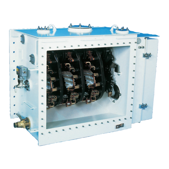
Lifting eye Cover for access to terminals, UZF only Attachment flange to transformer tank Terminals for conductors Pressure relay Oil valve Tap-changer tank Fig. 1. General arrangement of on-load tap-changer. 1ZSE 5492-115 en, Rev. 6 | Installation and commissioning guide UZE/UZF 9... -
Page 10: Required Tools
250/... 380/... 550/... 1050 1120 650/... 1050 1120 WARNING Do not energize the transformer until oil has been filled as per chapter 6, Oil filling, in this manual. 10 Installation and commissioning guide UZE/UZF | 1ZSE 5492-115 en, Rev 6... -
Page 11: Oil Conservator
1.4 Oil conservator The tap-changer has to be connected to an oil conservator, except when it is an UZE with expansion volume in the tank. Min 3° ABB recommends the use of a separate conservator for the tap-changer with both oil and air side separated from the main conservator of the transformer. -
Page 12: Filter Unit For Continuous Oil Filtration
1ZSC000562-AAD. UZE.N, UZE.T 200/... 250/... 380/... 550/... 1100 650/... 1100 UZF.N, UZF.T 200/... 250/... 380/... 550/... 1100 650/... 1100 12 Installation and commissioning guide UZE/UZF | 1ZSE 5492-115 en, Rev 6... -
Page 13: Receiving
24 hours at a temperature of max. 70 °C (158 °F) Fig. 5. Inspection on receipt before it is fitted to the transformer. See chapter 3, Drying. 1ZSE 5492-115 en, Rev. 6 | Installation and commissioning guide UZE/UZF 13... -
Page 14: Drying
The motor-drive mechanism should not be included in a vacuum process, as the process would remove the grease necessary for operation. 14 Installation and commissioning guide UZE/UZF | 1ZSE 5492-115 en, Rev 6... -
Page 15: Installation On The Transformer
(Fig. 7) with ABB glue 1234 0016-608, by brushing glue on both the gasket and the flange. Tap-changer flange a ≥ 4 mm Transformer tank Fig. 6. Welding detail. 1ZSE 5492-115 en, Rev. 6 | Installation and commissioning guide UZE/UZF 15... - Page 16 ABB glue 1234 0016-608 is a contact adhesive of nitrile rubber base. Sealing gasket Supporting gasket May consist of two gaskets Corner gasket Opening for draining View A – A Fig. 7. Gluing the gasket. 16 Installation and commissioning guide UZE/UZF | 1ZSE 5492-115 en, Rev 6...
-
Page 17: Assembly Of Accessories
On UZE the winding has to be connected from the rear. changer are then sealed by transport covers. On both UZE and UZF the cable lugs can be either crimped or 1. Remove the transport covers. brazed. The free distance between the cable lugs for adjacent 2. -
Page 18: Connection To The Oil Conservator
1.2 m. For a reinforced barrier, the oil level difference may be 8 m. Ø 52 Ø 100 Ø 130 Fig. 9. Attachment flange for oil conservator. 18 Installation and commissioning guide UZE/UZF | 1ZSE 5492-115 en, Rev 6... -
Page 19: Oil Filling
For correct oil level see section 5.3. UZE can be delivered with an oil expansion volume in the top 6. Shut the oil valve and disconnect the filling equipment. -
Page 20: Electrical Connection And Testing
Check the end stops. When trying to operate it electrically beyond the end position, the motor should not start. Check the mechanical end stop by trying to hand crank 20 Installation and commissioning guide UZE/UZF | 1ZSE 5492-115 en, Rev 6... -
Page 21: Transport
Drain the oil from the tap-changer. Close the opening to the conservator with a transport cover. UZE with oil expansion volume in the tank Drain the oil from the tap-changer. 1ZSE 5492-115 en, Rev. 6 | Installation and commissioning guide UZE/UZF 21... - Page 22 Repeat the test when the motor is Make sure that no tools or foreign objects are left in the motor cold. drive cabinet. Close the door. 22 Installation and commissioning guide UZE/UZF | 1ZSE 5492-115 en, Rev 6...
- Page 24 Contact us ABB AB Components SE-771 80 Ludvika, Sweden Phone: +46 240 78 20 00 Fax: +46 240 121 57 E-Mail: sales@se.abb.com www.abb.com/electricalcomponents...